
Welding defect
In metalworking, a welding defect is any flaw that compromises the usefulness of a weldment. There are many different types of welding defects, which are classified according to ISO 6520,[1] while acceptable limits for welds are specified in ISO 5817[2] and ISO 10042.[3]
Major causes[edit]
According to the American Society of Mechanical Engineers (ASME), the causes of welding defects can be classified as follows: 41% poor process conditions, 32% operator error, 12% using the wrong technique, 10% incorrect consumables, and 5% bad weld grooves.[4]
Hydrogen embrittlement[edit]
Residual stresses[edit]
The magnitude of residual stress caused by the heating, and subsequent cooling, from welding can be roughly calculated using:[5]

Where is Young's modulus, is the coefficient of thermal expansion, and is the temperature change. This approximates 3.5 GPa (510,000 psi) for steel.


Types[edit]
Cracks[edit]

Arc strikes[edit]
An arc strike is a discontinuity resulting from an arc consisting of any localized remelted metal, heat-affected metal, or change in the surface profile of any metal object.[6] Arc strikes result in localized base metal heating and very rapid cooling. When located outside the intended weld area, they may result in hardening or localized cracking and may serve as potential sites subsequent fracturing. In statically loaded structures, arc strikes need not be removed unless such removal is required in contract documents. However, in cyclically loaded structures, arc strikes may result in stress concentrations that would be detrimental to the serviceability of such structures, and arc strikes should be ground smooth and visually inspected for cracks.[7]
Cold cracking[edit]
Cold cracking—also known as delayed cracking, hydrogen-assisted cracking (HAC), or hydrogen-induced cracking (HIC)—is a type of defect that often develops after solidification of the weld when the temperature starts to drop from about 190 °C (375 °F); the phenomenon often arises at room temperature, and it can take up to 24 hours to appear even after complete cooling.[8] Some codes require testing of welded objects 48 hours after the welding process. This type of crack is usually observed in the heat affected zone (HAZ), especially with carbon steel, which has limited hardenability. For other alloy steels, with a high degree of hardenability, cold cracking could occur in both the weld metal and the HAZ. This crack mechanism can also propagate between grains and through grains.[9] Factors that can contribute to the occurrence of cold cracking are:[10]
- The amount of hydrogen (H2) dissolved in weld metal:
- Dissolved hydrogen in the weld metal is related to hydrogen embrittlement. Hydrogen content can be reduced by using hydrogen-free consumables. In the case of welding filler (especially in shielded metal arc welding (SMAW)) exposed to the atmosphere, proper electrode baking is recommended to eliminate moisture from flux. Preheating of the base material is also one of the techniques used to release hydrogen from the working object.
- Residual tensile stress:
- Residual tensile stress can cause cracks to propagate without any applied stress. This can be avoided by preheating the base metal, which reduces the different thermal expansion coefficients that will affect the cooling rate of weld metal. Utilizing low-yield-strength filler metal is also preferable because the magnitude of residual stresses can be equal to the σ yield of the metal. Therefore, the use of austenitic stainless steel or nickel-base filler could be considered due to its ductile nature. Also, post weld heat treatment (PWHT) will release any residual stresses on the weld joint.
- Hardness of weld metal and heat affected zone (HAZ):
- Hardness is correlated with the brittleness of the material. To reduce excessive hardness, preheating and PWHT can be applied to the object. Hardness values below 350 VHN have less tendency to crack.[10]
- Structure of weld metal and HAZ:
- Cold cracking in steels is associated with forming martensite as the weld cools. Hydrogen has very low solubility in martensite, which can lead to the gas being trapped inside the weld if care isn't taken. Slower cooling rates during the welding process help to avoid martensite formation. In addition, a slower cooling rate means a longer time at an elevated temperature, which allows more hydrogen to escape. A slower cooling rate is achieved by using high heat input and maintaining it during the welding.
The alloy composition of the base metal also has an essential role in the likelihood of a cold crack occurring, since that composition relates to the hardenability of materials. With high cooling rates, the risk of forming a hard, brittle structure in the weld metal and HAZ is more likely. The hardenability of a material is usually expressed in terms of its carbon content or, when other elements are taken into account, its carbon equivalent (CE) value.
- [8] (concentration is shown as percentage of weight)

Then, depending on the carbon content (with additional elements influencing the carbon equivalent index), steels can be classified into three zones, from their cold cracking behavior, as shown in the Graville diagram.[11]
- Zone I includes low-carbon and low-alloy steels with a carbon content lower than 0.10%. Materials that lie in this region are considered not crack-sensitive.
- Zone II includes most carbon steels with a carbon content above 0.10%. Steels in this zone can be prone to cold cracks. In this case, it is preferable to use low hydrogen filler and slow the cooling rate during welding process.
- Zone III includes alloy steels with a carbon content above 0.10% and a high carbon equivalent index. Materials in this zone are considered hard to weld because martensite formation is unavoidable, even under controlled cooling. Therefore, additional procedures, such as preheating and PWHT, are needed during the welding process.
Crater crack[edit]
Crater cracks occur when a welding arc is broken, a crater will form if adequate molten metal is available to fill the arc cavity.[12]
Hat crack[edit]

Hat cracks get their name from the shape of the weld cross-section, because the weld flares out at the face of the weld. The crack starts at the fusion line and extends up through the weld. They are usually caused by too much voltage or not enough speed.[12]
Hot cracking[edit]
Hot cracking, also known as solidification cracking, can occur with all metals, and happens in the fusion zone of a weld. Excess restraint in the use of material should be avoided to diminish the probability of this type of cracking, and a proper filler material should be utilized.[13] Other causes include a too-high welding current, poor joint design that does not diffuse heat, impurities (such as sulfur and phosphorus), preheating, welding speed being too fast, and long arcs.[14]
Underbead crack[edit]
An underbead crack, also known as a heat-affected zone (HAZ) crack,[15] forms a short distance away from the fusion line; it occurs in low alloy and high alloy steel. The exact causes of this type of crack are not entirely understood, but it is known that dissolved hydrogen must be present. The other factor that affects this type of crack is internal stresses resulting from: unequal contraction between the base metal and the weld metal, restraint of the base metal, stresses from the formation of martensite, and highlights from the precipitation of hydrogen out of the metal.[16]
Longitudinal crack[edit]
Longitudinal cracks run along the length of a weld bead. There are three types: check cracks, root cracks, and full centerline cracks. Check cracks are visible from the surface and extend partially into the weld. They are usually caused by high shrinkage stresses, especially on final passes, or by a hot cracking mechanism. Root cracks start at the root and extent part-way into the weld. They are the most common type of longitudinal crack because of the small size of the first weld bead. If this type of crack is not addressed, it will usually propagate into subsequent weld passes, which is how full cracks (a crack from the root to the surface) usually form.[12]
Reheat cracking[edit]
Reheat cracking is a type of cracking that occurs in HSLA steels—particularly chromium, molybdenum and vanadium steels—during post-heating. The phenomenon has also been observed in austenitic stainless steel. The poor creep ductility of the heat-affected zone causes such cracks. Any existing defects or notches aggravate crack formation. Conditions that help prevent reheat cracking include preliminary heat treating with a low-temperature soak and then with rapid heating to high temperatures, grinding or peening the weld toes, and using a two-layer welding technique to refine the HAZ grain structure.[17][18]
Root and toe cracks[edit]
A root crack is formed by the short bead at the root (of edge preparation)—at the beginning of the welding, with low current at the beginning, and with improper filler material. The primary reason for these types of cracks is hydrogen embrittlement. These defects can be eliminated using a high current at the starting and proper filler material. A toe crack occurs due to moisture content in the welded area; it is a surface crack so that it can be easily detected. Preheating and proper joint formation are a must for eliminating these types of defects.
Transverse crack[edit]
Transverse cracks are perpendicular to the direction of the weld. These are generally the result of longitudinal shrinkage stresses acting on weld metal of low ductility. Crater cracks occur in the crater when the welding arc is terminated prematurely. Crater cracks are typically shallow, hot cracks, usually forming single or star cracks. These cracks usually start at a crater pipe and extend longitudinally in the crater. However, they may propagate into longitudinal weld cracks in the rest of the weld.
Distortion[edit]
Welding methods that involve the melting of metal at the site of the joint are necessarily prone to shrinkage as the heated metal cools. Shrinkage then introduces residual stresses and distortion. Distortion can pose a major problem since the final product is not the desired shape. To alleviate certain types of distortion, the workpieces can be offset so that after welding, the product is the correct shape.[19] The following pictures describe various types of welding distortion:[20]
-
 Transverse shrinkage
 -
 Angular distortion
 -
 Longitudinal shrinkage
 -
 Fillet distortion
 -
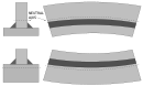 Neutral axis distortion


Gas inclusion[edit]
Gas inclusion—gas entrapment within the solidified weld—manifests itself in a wide variety of defects, including porosity, blow holes, and pipes (or wormholes). Gas formation can be from any of the following causes—high sulphur content in the workpiece or electrode, excessive moisture from the electrode or workpiece, too short of an arc, or wrong welding current or polarity.[15]
Other inclusions[edit]
There are two other types of inclusions: linear inclusions and isolated inclusions. Linear inclusions occur when there is slag or flux in the weld. Slag forms from the use of a flux, which is why this type of defect usually occurs in welding processes that use such flux, such as shielded metal arc welding, flux-cored arc welding, and submerged arc welding; but it can also occur in gas metal arc welding. This defect usually occurs in welds that require multiple passes when there is poor overlap between the welds. The poor overlap does not allow the slag from the previous weld to melt out and rise to the top of the new weld bead. It can also occur if the previous weld left an undercut or an uneven surface profile. To prevent slag inclusions, the slag should be cleaned from the weld bead between passes via grinding, wire brushing, or chipping.[21]
Isolated inclusions occur when rust or mill scale is present on the base metal.[22]
Lack of fusion and incomplete penetration[edit]
Lack of fusion is the poor adhesion of the weld bead to the base metal. Incomplete penetration is a weld bead that does not start at the root of the weld groove, leaving channels and crevices in the root of the weld. This causes serious issues in pipes because corrosive substances can settle in these areas. These types of defects occur when the welding procedures are not adhered to; possible causes include the current setting, arc length, electrode angle, and electrode manipulation.[23] Defects can be varied and classified as critical or noncritical. Porosity (bubbles) in the weld are usually acceptable to a certain degree. Slag inclusions, undercut, and cracks are usually unacceptable. Some porosity, cracks, and slag inclusions are visible and may not need further inspection to require their removal. Liquid Penetrant Testing (dye check) can verify minor defects. Magnetic Particle Inspection can discover Slag inclusions and cracks just below the surface. Deeper defects can be detected using Radiographic (X-rays) and/or Ultrasound (sound waves) testing techniques.
Lamellar tearing[edit]
Lamellar tearing is a welding defect that occurs in rolled steel plates that have been welded together in a way that creates shrinkage forces perpendicular to the faces of the plates and is caused mainly by sulfurous inclusions in the material.[24] Since the 1970s, changes in manufacturing practices, limiting the amount of sulfur used, have greatly reduced the incidence of this problem.[25]
Other causes include excess hydrogen in the alloy. This defect can be mitigated by keeping the amount of sulfur in the steel alloy below 0.005%.[25] Adding rare earth elements, zirconium, or calcium to the alloy, to control the configuration of sulfur inclusions throughout the metal lattice, can also mitigate the problem.[26]
Modifying the construction process to use cast or forged parts in place of welded parts can eliminate this problem, as Lamellar tearing only occurs in welded parts.[24]
Undercut[edit]

Undercutting is when the weld reduces the base metal's cross-sectional thickness and reduces the strength of the weld and workpieces. One reason for this type of defect is excessive current, which causes the edges of the joint to melt and drain into the weld, thus leaving a drain-like impression along the length of the weld. Another reason is poor technique that doesn't deposit enough filler metal along the edges of the weld. A third reason is use of an incorrect filler metal, which will create greater temperature gradients between the center of the weld and the edges. Other causes include too small of an electrode angle, a dampened electrode, excessive arc length, and slow welding speed.[27]
References[edit]
- ^ BS EN ISO 6520-1: "Welding and allied processes — Classification of geometric imperfections in metallic materials — Part 1: Fusion welding"(2007)
- ^ BS EN ISO 5817: "Welding — Fusion-welded joints in steel, nickel, titanium and their alloys (beam welding excluded) — Quality levels for imperfections" (2007)
- ^ BS EN ISO 10042: "Welding. Arc-welded joints in aluminium and its alloys. Quality levels for imperfections" (2005)
- ^ Matthews, Clifford (2001), ASME engineer's data book, ASME Press, p. 211, ISBN 978-0-7918-0155-0.
- ^ Bull, Steve (2000-03-16), Magnitude of stresses generated, University of Newcastle upon Tyne, archived from the original on 2009-04-16, retrieved 2009-12-06.
- ^ AWS A3.0: 2020 – Standard Welding Terms and Definitions
- ^ aisc.org/steel-solutions-center/engineering-faqs/8.5.-repairs
- ^ a b Cold Cracking of Weld (PDF).
- ^ Pluvinage, Guy; Capelle, Julien; Schmitt, Christian (2016-01-01), Makhlouf, Abdel Salam Hamdy; Aliofkhazraei, Mahmood (eds.), "Chapter 3 – Methods for assessing defects leading to gas pipe failure", Handbook of Materials Failure Analysis with Case Studies from the Oil and Gas Industry, Butterworth-Heinemann, pp. 55–89, doi:10.1016/b978-0-08-100117-2.00003-0, ISBN 978-0-08-100117-2, retrieved 2022-05-21
- ^ a b Lec 40 – Cracking of Welded Joints II: Cold Cracks, retrieved 2022-05-21
- ^ Kurji, R.; Coniglio, N. (2014-11-14). "Towards the establishment of weldability test standards for hydrogen-assisted cold cracking". The International Journal of Advanced Manufacturing Technology. 77 (9–12): 1581–1597. doi:10.1007/s00170-014-6555-3. hdl:10985/9418. ISSN 0268-3768. S2CID 253678716.
- ^ a b c Raj, Jayakumar & Thavasimuthu 2002, p. 128.
- ^ Cary & Helzer 2005, pp. 404–405.
- ^ Bull, Steve (2000-03-16), Factors promoting hot cracking, University of Newcastle upon Tyne, archived from the original on 2009-04-16, retrieved 2009-12-06.
- ^ a b Raj, Jayakumar & Thavasimuthu 2002, p. 126.
- ^ Rampaul 2003, p. 208.
- ^ Bull, Steve (2000-03-16), Reheat cracking, University of Newcastle upon Tyne, archived from the original on 2009-04-16, retrieved 2009-12-06.
- ^ Bull, Steve (2000-03-16), Reheat cracking, University of Newcastle upon Tyne, archived from the original on 2009-04-16, retrieved 2009-12-06.
- ^ Weman 2003, pp. 7–8.
- ^ Bull, Steve (2000-03-16), Welding Faults and Defects, University of Newcastle upon Tyne, archived from the original on 2009-04-16, retrieved 2009-12-06.
- ^ Defects/imperfections in welds – slag inclusions, archived from the original on 2009-12-05, retrieved 2009-12-05.
- ^ Bull, Steve (2000-03-16), Welding Faults and Defects, University of Newcastle upon Tyne, archived from the original on 2009-04-16.
- ^ Rampaul 2003, p. 216.
- ^ a b Bull, Steve (2000-03-16), Welding Faults and Defects, University of Newcastle upon Tyne, archived from the original on 2009-04-16.
- ^ a b Still, J. R., Understanding Hydrogen Failures, retrieved 2009-12-03.
- ^ Ginzburg, Vladimir B.; Ballas, Robert (2000), Flat rolling fundamentals, CRC Press, p. 142, ISBN 978-0-8247-8894-0.
- ^ Rampaul 2003, pp. 211–212.
Bibliography[edit]
- Cary, Howard B.; Helzer, Scott C. (2005), Modern Welding Technology, Upper Saddle River, New Jersey: Pearson Education, ISBN 0-13-113029-3.
- Raj, Baldev; Jayakumar, T.; Thavasimuthu, M. (2002), Practical non-destructive testing (2nd ed.), Woodhead Publishing, ISBN 978-1-85573-600-9.
- Rampaul, Hoobasar (2003), Pipe welding procedures (2nd ed.), Industrial Press, ISBN 978-0-8311-3141-8.
- Moreno, Preto (2013), Welding Defects (1st ed.), Aracne, ISBN 978-88-548-5854-1, archived from the original on 2017-05-19, retrieved 2017-04-26.
- Weman, Klas (2003), Welding processes handbook, New York, NY: CRC Press, ISBN 0-8493-1773-8.