File:Negative resistance stability regions VCNR.svg

Page contents not supported in other languages.
This is a file from the Wikimedia Commons
From Wikipedia, the free encyclopedia

Original file(SVG file, nominally 627 × 597 pixels, file size: 24 KB)

Summary

Description
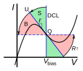
English: A typical characteristic curve of a voltage-controlled negative differential resistance (VCNR or N type) device, showing regions of stable, unstable, and bistable load lines. A DC bias voltage Vbias sets the operating point (Q1) in the middle of the negative resistance region where the device has differential resistance Δvi = -r, as shown by the DC load line (DCL). The AC load line, set by the AC impedance Z facing the device, passes through the Q point at a different angle depending on Z. Increasing Z causes the load line to rotate counterclockwise.
  • if Z < r (green region, example load line L1) the load line intersects the curve once at Q1 so the circuit is stable.
  • if Z = r (line L2) the net resistance of the circuit, R+r = 0, so the circuit is unstable and will oscillate.
  • If Z > r (red region, example load line L3) the load line intersects the curve three times, at Q1, Q2, and Q3. The middle point Q1 is unstable, but the two outer operating points are stable, so the circuit is bistable. This biasing can be used to make flip-flops.
Since the device is stable for resistances below r, voltage controlled negative resistances are called short-circuit stable. Devices with this type of negative resistance include tunnel diodes and Gunn diodes.
Date
Source Own work
Author Chetvorno
Other versions File:Negative resistance stability regions CCNR.svg

Licensing

I, the copyright holder of this work, hereby publish it under the following license:
Creative Commons CC-Zero This file is made available under the Creative Commons CC0 1.0 Universal Public Domain Dedication.
The person who associated a work with this deed has dedicated the work to the public domain by waiving all of their rights to the work worldwide under copyright law, including all related and neighboring rights, to the extent allowed by law. You can copy, modify, distribute and perform the work, even for commercial purposes, all without asking permission.

Captions

Add a one-line explanation of what this file represents

Items portrayed in this file

depicts

26 December 2012

File history

Click on a date/time to view the file as it appeared at that time.

Date/TimeThumbnailDimensionsUserComment
current20:05, 13 May 2013Thumbnail for version as of 20:05, 13 May 2013627 × 597 (24 KB)ChetvornoChanged red and green stability region color gradients back to solid color sectors, minor label adjustments
04:31, 13 May 2013Thumbnail for version as of 04:31, 13 May 2013627 × 597 (25 KB)ChetvornoAdded example load lines L1, L2, and L3, changed red and green stability regions from sectors to radial color gradients, and changed some labels
19:45, 26 December 2012Thumbnail for version as of 19:45, 26 December 2012675 × 578 (18 KB)ChetvornoAdded label for Q point and minor format adjustments
19:24, 26 December 2012Thumbnail for version as of 19:24, 26 December 2012675 × 578 (18 KB)ChetvornoUser created page with UploadWizard
The following pages on the English Wikipedia use this file (pages on other projects are not listed):

Global file usage

The following other wikis use this file:

Metadata