
South African Class 19C 4-8-2
| South African Class 19C 4-8-2 | |||||||||||||||||||||||||||||||||||||||||||||||||||||||||||||||||||||||||||||||||||||||||||||||||||||||||||||||||||||||||||||
|---|---|---|---|---|---|---|---|---|---|---|---|---|---|---|---|---|---|---|---|---|---|---|---|---|---|---|---|---|---|---|---|---|---|---|---|---|---|---|---|---|---|---|---|---|---|---|---|---|---|---|---|---|---|---|---|---|---|---|---|---|---|---|---|---|---|---|---|---|---|---|---|---|---|---|---|---|---|---|---|---|---|---|---|---|---|---|---|---|---|---|---|---|---|---|---|---|---|---|---|---|---|---|---|---|---|---|---|---|---|---|---|---|---|---|---|---|---|---|---|---|---|---|---|---|---|
 No. 2439, Outeniqua Transport Museum, 22 April 2006 | |||||||||||||||||||||||||||||||||||||||||||||||||||||||||||||||||||||||||||||||||||||||||||||||||||||||||||||||||||||||||||||
| |||||||||||||||||||||||||||||||||||||||||||||||||||||||||||||||||||||||||||||||||||||||||||||||||||||||||||||||||||||||||||||
| |||||||||||||||||||||||||||||||||||||||||||||||||||||||||||||||||||||||||||||||||||||||||||||||||||||||||||||||||||||||||||||
| |||||||||||||||||||||||||||||||||||||||||||||||||||||||||||||||||||||||||||||||||||||||||||||||||||||||||||||||||||||||||||||
| |||||||||||||||||||||||||||||||||||||||||||||||||||||||||||||||||||||||||||||||||||||||||||||||||||||||||||||||||||||||||||||
The South African Railways Class 19C 4-8-2 of 1935 was a steam locomotive.
In 1935, the South African Railways placed fifty Class 19C steam locomotives with a 4-8-2 Mountain type wheel arrangement in service. It was the first South African locomotive class to use rotary cam poppet valve gear and also the first to be built new with a Watson Standard boiler.[1][2][3][4]
Manufacturer[edit]
When the need for more branch line locomotives became apparent in 1934, tenders were invited by the South African Railways (SAR) for another fifty Class 19B locomotives with Walschaerts valve gear, but redesigned by Chief Mechanical Engineer A.G. Watson with his Watson Standard no. 1A boiler. When the tenders were received, it was found that the North British Locomotive Company of Glasgow, Scotland, had also tendered for a locomotive with rotary cam poppet valve gear as an alternative to Walschaerts valve gear.[1][2][3][5]
Even though this would increase the cost per locomotive by £200, Watson decided to accept this tender in view of the good reports he had received concerning poppet valve gear. This variation on the design led to these locomotives being designated Class 19C when they were delivered in 1935.[1][2][3]
Characteristics[edit]
Tenders[edit]
All fifty Class 19C locomotives were erected at the Salt River shops and numbered in the range from 2435 to 2484, and many remained stationed at Cape Town while being subjected to exhaustive testing. As built, the Class 19C was delivered with Type MT tenders with a 12 long tons (12.2 tonnes) coal and a 6,000 imperial gallons (27,300 litres) water capacity, even though the axle load of 16 long tons 11 hundredweight (16,820 kilograms) of these tenders exceeded the permissible limits on the branch lines for which the Class 19C was intended. Upon delivery, their new Type MT tenders were exchanged for the smaller modified Type MP1 tenders from some of the reboilered mainline locomotives. The Type MP1 had a lighter axle load of 13 long tons 15 hundredweight (13,970 kilograms) and was therefore more suitable for branch line work. This policy was followed with all the Classes 19B, 19C and 19D, except the last batch of Class 19D which was delivered with Type MX torpedo tenders.[1][6][7]
Watson Standard boilers[edit]
Soon after A.G. Watson was appointment as CME in 1929, he set out on a program of standardisation of locomotive boilers and engine parts which ultimately led to a considerable reduction in the time taken for locomotive repairs. At the time, 88 different types of locomotive were in service, for which some fifty types of replacement boiler were still being ordered prior to 1929.[4]

The Class 19C was the first to be built new with Watson Standard boilers. The no. 1A boiler had a larger superheater than the Class 19B. In a break with prior custom, the ash pan and running boards were affixed to the locomotive frame instead of to the boiler to facilitate easier removal of the boiler for repairs. The Class 19C was also built with Watson's altered cab with a slanted front to facilitate access to the firebox stays on the sides ahead of the cab. The Watson cab, like the Watson Standard boiler, was to become standard on later SAR steam locomotive classes.[2][4][8]
The first five Watson Standard boilers to be designed were the numbers 1, 1A, 2, 2A and 2B. The no. 1 boiler was suitable for the Classes 5, 5B, 10A, 10B and 10C locomotives. The no. 1A boiler was similar to the no. 1, but with the boiler barrel lengthened by 2 feet 5 inches (737 millimetres), and was suitable for the Classes 19, 19A and 19B. Like the Class 19C, the Class 19D would also be built new with no. 1A boilers.[4]
The no. 2 boiler was suitable for the Classes 3, 3B, 4A, 12, 12B, 14, 14A and 14C locomotives. The no. 2A boiler was similar to the no. 2, but with the boiler barrel lengthened by 2 feet 4 inches (711 millimetres), and was suitable for the Classes 15, 15A and 15B locomotives. The no. 2B boiler was also similar to the no. 2, but with the boiler barrel shortened by 1 foot (305 millimetres), and was suitable for the Classes 16, 16B and 16C locomotives.[4]
These were later followed by the numbers 3A and 3B boilers. The no. 3A boiler was suitable for the Class 16E locomotive, while the no. 3B boiler was 3 feet 5+1⁄2 inches (1,054 millimetres) longer and suitable for the Classes 15E, 15F, 21 and 23 locomotives.[4]
Copper and steel fireboxes[edit]
Some of the locomotives were built with steel fireboxes for use in those areas where good or treated water was readily available, while others were still equipped with copper or composite fireboxes for use in areas with poor water quality.[6][7]
Copper or composite fireboxes are considerably more expensive to manufacture and repair than steel ones. It was only by the late 1960s, when severe corrosion was no longer a big problem as a result of the availability of water treatment facilities throughout the country, that copper and composite fireboxes were no longer considered necessary.[9]
Rotary cam poppet valve gear[edit]
The rotary cam poppet valve gear consists of two admission valves and two exhaust valves per cylinder, operated by a camshaft arranged in a box fixed to each cylinder between the valve chambers. The cam boxes are self-contained and detachable, and replacement cam boxes can be fitted at running sheds within a few hours. The camshafts are driven from the return cranks on the driving wheels through worm wheels and universal propeller shafts, arranged so that the camshafts and the coupled wheels revolve at the same speed.[2]
There were originally eight cams for forward motion and three for reverse, which gave a range of cut-offs from 15% to 85% in forward gear. The hand reversing screw spindle carried a disk, suitably notched with a locking device to ensure that the cam rollers would be in the centre of the selected cams under working conditions. During drifting, the reversing gear is placed in the neutral position where the exhaust valves are held fully open. These conditions were ideal for drifting and superior to any Walschaerts valve gear in admitting steam to the steam chests, even with cylinders equipped with by-pass valves, snifting valves and drifting valves.[2]
In service, some trouble was experienced with transmission shaft joints and with worn cams and rollers. If the valves were set with the engine cold, there appeared to be some distortion under working conditions due to the high temperature of superheated steam which caused deterioration of the valve events. Drivers also reported that, when the engines were standing or moving at very slow speed, it was difficult to reverse since the cam rollers were not readily able to climb over the inclined surfaces leading from one cam to another. Trouble was also experienced with steam leaking past the tappet spindles into the cam boxes where it boiled up the oil and caused it to overflow from the cam boxes. This was overcome by serrating the collars of the spindle bushes to allow the steam to escape and prevent entry into the cam boxes.[2]
_%26_AG_Watson.jpg)
The photograph alongside shows a Class 19C locomotive after a record speed test run during which the engine achieved a speed of 67 miles per hour (108 kilometres per hour). A.G. Watson is standing sixth from left in the group in front of the locomotive, with hat in hand.
An official test was conducted in 1938 to compare the steam consumption of the poppet valve Class 19C with the piston valve Class 19D. The Class 19D performed slightly better. However, the valve travel of the Class 19D is 7+1⁄2 inches (191 millimetres) compared to a valve travel of about 4+3⁄4 inches (121 millimetres) in all previous engines fitted with piston or slide valves. It was concluded that, had the valve travel of the Class 19D been retained at 4+3⁄4 inches (121 millimetres), the test would have shown an advantage for the poppet valves.[2]
Balancing[edit]
The balancing of these locomotives represented another advance on former practices. Until then, locomotives had been balanced to an extent of 50% to 75% of their reciprocating parts, and fully as regards their revolving parts.[1][2]
On the Class 19C, the proportion of reciprocating parts balanced was reduced to 20%, which resulted in a big decrease of vertical hammer blow to not more than 18 long hundredweight (914 kilograms) on any wheel at 50 miles per hour (80 kilometres per hour). Similar balancing methods on subsequent new locomotives enabled the SAR to adopt axle loads exceeding those permitted on many other railways of the world for comparable weight of rail.[1][2]
Modifications[edit]
In the Western Cape, wheatland fires caused by locomotives were a huge problem for farmers as well as for the SAR who had to pay out the claims. In the late 1960s Johannes Barnard, the assistant locomotive superintendent at Cape Town, invented a self-cleaning smokebox and a way to blow char out of the smokebox when the engine was standing in non-sensitive places such as at water stops. While on the run, excess char was diverted into a box mounted below the smokebox door. The consensus among railwaymen at the time was that these modifications were not entirely effective, but they remained in use for at least ten years nonetheless.[10][11]
Another of Barnard's experiments was with spark-extinguishing equipment installed on a Class 19C and a Class GEA Garratt. The spark extinguishers were mounted on the chimneys and consisted of two long tubes to extend the exhaust horizontally. The tubes had spray pipes around their vertical outlets at the end to drench any sparks that may have survived the journey along the tubes. In the case of Class 19C no. 2456 the tubes fed the exhaust rearward to the outlets just ahead of the cab, which led to the engine being nicknamed Takbok (reindeer). The experiments were not successful.[12]
Service[edit]
The Class 19C was designed for mainline as well as branch line service. They initially worked in the Witwatersrand area, the Eastern Cape and Western Cape. In the Western Cape, Class 19Cs were the mainstay of the service for more than forty years. The Calvinia and Sakrivier branches in the Northern Cape were worked by Class 19C locomotives at least from 1950, probably earlier. In later years, around 1970, a few were stationed at Bloemfontein from where they worked the line to Aliwal North.[3][8][11]
_IDR.JPG)
The Poppet valves made the Class 19C a very free-running locomotive, although it required special maintenance techniques. As a result, the whole class was allocated to the Western Cape during the Second World War and based at the Paardeneiland shed in Cape Town. From here, they worked on branch lines such as those from Cape Town to Saldanha, along the long branch line via Klawer to Bitterfontein, and across Sir Lowry's Pass to Caledon, Bredasdorp and Protem in the Overberg.[3][8]
Locomotives working between Malmesbury and Bitterfontein were usually equipped with Type MX torpedo tenders. Bitterfontein in the thirstland was a rare terminus in that it had no locomotive water at all. Engines had to work out from the last water stop at Lutzville and back, a round trip of 100 miles (161 kilometres) which including climbing from almost sea level to an elevation of more than 1,100 feet (335 metres) at Bitterfontein while performing shunting along the way. When a Class 19C with its standard Type MP1 tender was used, it had to take along a Type X-17 or Type X-20 water tender.[13]
They were withdrawn from service in 1978. One, no. 2439, was preserved, but none of them were sold into industry, firstly because of the special maintenance required for the poppet valves and secondly because Cape Town was a long distance away from any potential industrial operators, which would increase the cost of relocation after purchase.[3][8]
Preservation[edit]
| Number | Works nmr | THF / Private | Leaselend / Owner | Current Location | Outside South Africa | ? |
|---|---|---|---|---|---|---|
| 2439 | NBL 24172 | THF | Transnet Heritage Foundation | Outiniqua Transport Museum |
Illustration[edit]
-
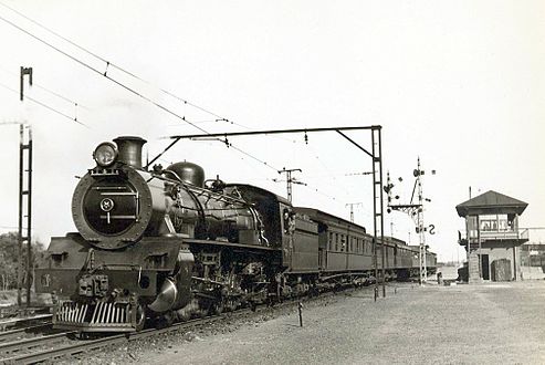 Class 19C headed towards Bellville from Cape Town, c. 1940
 -
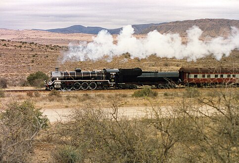 No. 2439 on the Humefield-Klipplaat line, 1 October 1989
 -
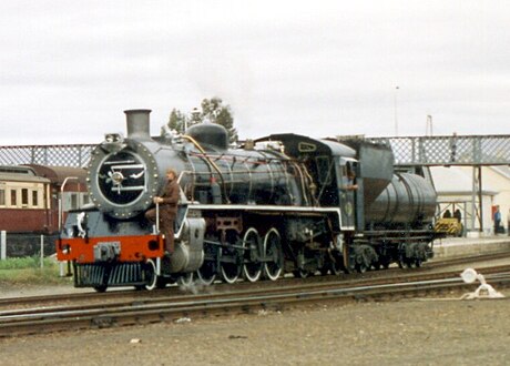 No. 2439 at Klipplaat, 1 October 1989
 -
 No. 2439 at the Outeniqua Transport Museum, 15 April 2013
.jpg)
_a.jpg)
_b.jpg)
.JPG)
References[edit]
- ^ a b c d e f Holland, D. F. (1972). Steam Locomotives of the South African Railways. Vol. 2: 1910-1955 (1st ed.). Newton Abbott, England: David & Charles. pp. 68–71, 93. ISBN 978-0-7153-5427-8.
- ^ a b c d e f g h i j Espitalier, T.J.; Day, W.A.J. (1946). The Locomotive in South Africa - A Brief History of Railway Development. Chapter VII - South African Railways (Continued). South African Railways and Harbours Magazine, August 1946. pp. 629-630.
- ^ a b c d e f Paxton, Leith; Bourne, David (1985). Locomotives of the South African Railways (1st ed.). Cape Town: Struik. pp. 10–11, 69–72. ISBN 0869772112.
- ^ a b c d e f Espitalier, T.J.; Day, W.A.J. (1946). The Locomotive in South Africa - A Brief History of Railway Development. Chapter VII - South African Railways (Continued). South African Railways and Harbours Magazine, July 1946. pp. 542-543.
- ^ North British Locomotive Company works list, compiled by Austrian locomotive historian Bernhard Schmeiser
- ^ a b South African Railways & Harbours/Suid Afrikaanse Spoorweë en Hawens (15 Aug 1941). Locomotive Diagram Book/Lokomotiefdiagramboek, 3'6" Gauge/Spoorwydte. SAR/SAS Mechanical Department/Werktuigkundige Dept. Drawing Office/Tekenkantoor, Pretoria. pp. VIII, 45.
- ^ a b South African Railways & Harbours/Suid Afrikaanse Spoorweë en Hawens (15 Aug 1941). Locomotive Diagram Book/Lokomotiefdiagramboek, 2'0" & 3'6" Gauge/Spoorwydte, Steam Locomotives/Stoomlokomotiewe. SAR/SAS Mechanical Department/Werktuigkundige Dept. Drawing Office/Tekenkantoor, Pretoria. pp. VIII, 6a-7a, 28, 45.
- ^ a b c d Durrant, AE (1989). Twilight of South African Steam (1st ed.). Newton Abbott: David & Charles. pp. 63–64. ISBN 0715386387.
- ^ SAR Code of Practice No. 7 (Boilers), Part 3A.811 dated May 1968 - Procedure to be followed when copper plates of complete copper or composite fireboxes require to be renewed
- ^ Soul of A Railway, System 1, Part 2: Cape Town to Wellington. Caption 37. (Accessed on 26 November 2016)
- ^ a b Soul of A Railway, System 1, Part 7: The Caledon train. Captions 4, 61. (Accessed on 29 November 2016)
- ^ Soul of A Railway, System 1, Part 8: Caledon line freight part 1: Cape Town-Elgin, the fruit traffic. Captions 2, 29, 68. (Accessed on 29 November 2016)
- ^ Soul of A Railway, System 1, Part 11: Cape Town-Kraaifontein-Malmesbury-Bitterfontein by C P Lewis. Caption 27. (Accessed on 2 December 2016)