
Talk:Phase-locked loop
| This is the talk page for discussing improvements to the Phase-locked loop article. This is not a forum for general discussion of the article's subject. |
Article policies
|
| Find sources: Google (books · news · scholar · free images · WP refs) · FENS · JSTOR · TWL |
| This article is rated B-class on Wikipedia's content assessment scale. It is of interest to the following WikiProjects: |
|||||||||||
| |||||||||||

Untitled[edit]
"might have an internal 2.4 GHz core clock which is phase aligned to a bus clock running at 100 MHz"
- Isn't the 100 MHz phase-aligned to the 2.4 GHz? Hmmm... I guess not. - Omegatron 17:13, Mar 2, 2005 (UTC)
- Never heard of the term phase aligned. What does it mean?--Light current 01:10, 28 March 2006 (UTC)
PC-centric bias?[edit]
I don't think an article discussing something as fundamental as phase-locked loops should start off with a fairly weird and trivial application in desktop computers. It'd be like discussing European history and starting with a list of opening dates of McDonalds' franchises in Paris. Sure, it's part of the subject but there's a *lot* going on that's more central to the topic. I'm putting this article on my to-do list but it may be a while - can someone reorganize it and mention more of the history and broad sweep of applications before obsessing on nit-picky PC guts? --Wtshymanski 17:13, 22 Apr 2005 (UTC)
- **** I agree. Start with fundamentals, then bridge to specifics. -- Steve -- 00:44, 10 September 2007 (UTC)
- That's just an artifact of whoever started the article and didn't know about any other applications, most likely. Fix it. :-) - Omegatron 17:39, Apr 22, 2005 (UTC)
- **** Obviously. -- Steve -- 00:44, 10 September 2007 (UTC)
- Actually, generating clocks for microprocessors isn't "trivial" at all. Probably the most common purpose for PLLs, actually. - Omegatron 17:41, Apr 22, 2005 (UTC)
- Commonplace, sure, but not especially interesting compared to the other neat things PLLs do. I've gone through my library at home but I can't find any good history of the technique. There's got to be some rack of vacuum tubes out there that was the first PLL. --Wtshymanski 00:57, 23 Apr 2005 (UTC)
240.182
- **** Correct, and should be mentioned after fundamentals. -- Steve -- 00:44, 10 September 2007 (UTC)
- Yeah, I agree. That's why I started working on math fundamentals. That's how I learned. I haven't had time to get much further with it. I wanted to include simple reference solutions for common loop filters, e.g. one pole RC, lag-lead, integrator etc. I usually re-derive all the Laplace transforms every time I design one because I can't find the equations from the last time ;-) There are references out there, but most of them aren't very good. I added a couple of transforms to the Laplace transform article for just this reason. -- Madhu 23:42, 23 October 2005 (UTC)
- **** This is understandable because calculating the effects of feedback is not served well by lower level math - believe me, I wish it was. As a Control Theory major in college (later an EE specializing in PLL design), it was obvious to me that simpler techniques are very inadequate and that normal (non - pole/zero, phase/gain margin, or other control theory) concepts don't help much for understanding what is going on. I struggled through the math and eventually developed a good "feel" for it. -- Steve -- 00:44, 10 September 2007 (UTC)
Time for a rewrite[edit]
The article is getting a little disorganized again and I've just pruned some apparent redundancies and added a section break. --Wtshymanski 15:03, 4 November 2005 (UTC)
PPL?[edit]
This is listed on the "PPL" disambiguation page, but "PLL" redirects here and is given in the article as the acronym. Is it also referred to as PPL sometimes, or is it just there by mistake? -Elmer Clark 07:23, 6 February 2006 (UTC)
- **** I've never seen it called this. May be a common fat-finger error. Only the Phase Lock vs. Locked usage. -- Steve -- 00:44, 10 September 2007 (UTC)
Mechanical analogy[edit]
The mechanical analogy refers to a frequency locked loop- not a PLL and is therefore incorrect. This section needs rewriting explaining the phase locking operation. --Light current 21:07, 18 February 2006 (UTC)
- **** Thus my comments on analogies in general. I like the marching band suggestion. -- Steve -- 00:44, 10 September 2007 (UTC)
- I think the guitar tuning is a fine example. However, there should definitely be wording added to clarify how it is inaccurate. It would have confused me if I did not check the Talk page and find the discussions here. 71.245.36.73 (talk) 20:41, 19 January 2008 (UTC)
just checking[edit]
By multiplying the oscillator and the reference signals, this generates an output consisting of a low-frequency signal whose amplitude is related to the phase difference,
- Should this link to beat frequency? — Omegatron 03:01, 16 April 2007 (UTC)
- I wouldn't think so. Beat frequencies are what you get when you add signals together, as in tuning a guitar string with a fork. Multiplying the signals is heterodyning, which gives both high (fA + fB) and low (|fA - fB|) frequency comonents, and if you filter the high-frequency component out, leaving the difference component, it is also known as band shifting. --97.99.113.227 16:15, 5 August 2007 (UTC)
- **** OOPS! It could link. I'd have to re-read that article, though.
- Beat frequency _is_ a difference frequency obtained in the non linear operation of (usually) the detector (ears can also sometimes produce it) . This is due to the fact that nonlinearity of any type produces some multiplicitive effect. The Sum/Difference effect is the result of multiplication of the two signals - one signal causing some type of gain change (of the circuit) for the other signal. Simple addition of the signale will not do it. There may be some nonlinearity in the (non-ideal) adding process and therefore a beat resulting. Since tuning a guitar is a different thing altogether I think is is inappropriate here. I'd have to think about what causes instrument tuning beats - It may be a good analogy...I think there are two effects to consider there, but won't elaborate.
- While I think I understand the intent of the orignal quote: "output consisting of a low-frequency signal whose amplitude is related to the phase difference" is poorly stated. For an analog PD (mixer), the "low-frequency signal" will only be present when out of lock and the frequencies not equal, thus producing the difference frequency (or beat). The Amplitude will be fixed. I *suspect* the intent was more like "When locked, the output *voltage* will be proportional to the phase difference. "
**** PD section[edit]
- First describe its purpose, then *general* types, then examples of those types. Remove "An important part". _ALL_ PLL parts are important. The rest is ok, except the phase does not always have to go to zero. Type 1 loops have a constant, non zero error.
- On types of PDs:
- There are two major types:
- 1- Analog. Describe the multiplying process, sum/diff freqs, 90 degree settling point, dual requirements of the low pass filter and the resulting capture/lock range concepts. Examples, 4-Quad analog mult and double balanced diode mixer.
- 2- Digital. There are two subtypes.
- A- The XOR, analogous to the analog types (unavoidable pun). This type is NOT fundamentally different from the above analog types and may be better placed there. It depends on how you wish to clasify them - by functionality or simply circuit type - I think here is ok. Explain that square wave inputs, or nearly so, are required and all other analog concepts apply.
- B- The phase/freq (zero phase error) type. Most complex, edge triggered, Up/ Down outputs are difference between input edges, charge pump, lock detect output possible. The 4044 and its decendants.
-- Steve -- 00:44, 10 September 2007 (UTC)
REQUEST FOR FEEDBACK.[edit]
Intro has redundancies and unneeded info. Recommended re-write of intro:
A phase-locked (or phase-lock) loop (PLL) is an electronic control system that generates a signal that is locked to the phase of an input or reference signal. This is accomplished in a common negative feedback configuration by comparing the output of a voltage controlled oscillator to the input reference signal using a phase detector. The phase detector output is then used to drive the phase of the oscillator towards that of the input reference signal.
This type of circuit is widely used in radio, telecommunications, computers and other electronic applications in order to either :
1- Generate a frequency or frequencies that is/are made as stable as some other reference frequency or
2- Detect a frequency.
This technique is widely used in modern electronic devices, with output frequencies from a fraction of a cycle per second up to many gigahertz.
- 2 is more than just detect frequency. I'd phrase it as "Detect a repeating reference signal in a received signal, and generate a recovered version of that reference, usually for later use as a clock for decoding the data from the received signal.
- I'd add 3- Buffer a clock to one or more distant loads in such a way as to remove the phase offset caused by the propagation delay of the clock through wiring or other buffer devices. --97.99.113.227 16:23, 5 August 2007 (UTC)
- OK, I like it. I'd pull these out and that that makes 4.
1- Generate freq or freqs 2- Detect freq 3- Extract clock 4- Compensate for phase skew. -- Steve -- 00:44, 10 September 2007 (UTC)
HISTORY:[edit]
Did the 1932 French paper actually propose locking the phase, or was it only the common AFC ?
What year did Signetics introduce the IC?
STRUCTURE AND FUNCTION:[edit]
Phase-lock loops can be implemented in analog or digital form.
- **** Software as well. -- Steve -- 00:44, 10 September 2007 (UTC)
BLOCK DIAGRAM:[edit]
The feedback block should be generalized to just a block. It can be nothing, a divider, a programmable divider, a multiplier, a mixer or a combination of these. I believe an explanation of the effect of each of these is appropriate.
ANALOGY:[edit]
Analogies should be simpler examples that are something commonly familiar that the reader can identify with to aid in understanding the new concept. A mechanical analogy is inappropriate, I believe. The guitar tuning is ok, but, someone with basic understanding of electronics should understand the words without an analogy. A common furnace and thermostst may be a better basic control system analogy.
DIGITAL PLL[edit]
I have never seen a PLL used for a UART. Every time I run into a UART, it only divides down a reference clock to get its data clock; there is no phase-lock, VCO, or phase detector. This is why you see such interesting oscillator frequencies as 1.8432 MHz for sale (1.8432 MHz / 32 = 57.6 kbps, for example). The closest thing to a phase lock is the state machine for detecting the falling edge of the start bit, and it discards its "phase lock" information almost immediately (an error in the clock or data rate can cause the stop bit to be misinterpreted as the last data bit, or missed entirely). If anyone has an example, please give it, but I'd hardly think it was a common application.
That said, they're used all over the place in high-speed (Mbps/Gbps) serial links. But that's generally two applications: multiplying up a reference clock to the bit rate on the transmit side, and recovering the clock from the data on the received side. --97.99.113.227 16:34, 5 August 2007 (UTC)
ANALOG PLL[edit]
This should go before digital and be (as it tried to be) the general overview in more detail. This does not describe a basic PLL.
1- The U/D PD and charge pump are an advanced type. For a type 0 loop, the PD only is needed and the phase error is NOT brought to zero, but only to some fixed difference. As in the mixer or Exclusive OR PD & filter. The charge pump makes it a type 1 which does get the phase error to zero.
2- While the loop compensator does almost always have a ‘low pass’ characteristic and is frequently called as such, its primary purpose is to make the loop stable and defines its dynamic performance (lock time, lock range, pull-in range, damping, etc). It should also be noted that classical control theory methods can be used to determine loop dynamics provided the transfer functions of the individual blocks are well known.
3- The “bias generator” and “output converter” (whatever that is) are irrelevant in a basic description.
4- Again, the divide by N is also irrelevant for basics.
5- The “smooting” effect of the low pass filter is secondary to its primary purpose of determining loop dynamics. It is a "loop compensator". When spurious caused by VCO control line ‘ripple’ is a factor, then the low pass characteristics between the PD and VCO become important and often there is a trade-off between the loop dynamics and spurious. When more attenuation of spurious is needed, this can start to affect loop dynamics and more filtering usually requires slowing the loop.
- **** P.S. The analog and XOR PD types have what can be considered to be excessive output ripple so that the low pass characteristics of the filter frequently greatly over-shadow the loop compensation considerations. In the complex types of PD, the loop compensating characteristics (lock time and settling characteristics) are a larger consideration and the low-pass (high frequency attenuating) characteristics become secondary, but not unimportant or trivial. -- Steve -- 00:44, 10 September 2007 (UTC)
PHASE DETECTOR:[edit]
”…such that the phase between the two inputs becomes zero.” Not generally the case. Only in type 1, and higher, Loops.
The Exclusive-OR is the digital dual of the multiplier/mixer.
I’m not familiar with the “Bang-Bang” PD.
OSCILLATOR:[edit]
Only describe a VCO and mention that there are several types. LC, crystal, SAW, Ring, digital gate, multivibrator. Should just link to full articles on those types.
”…A voltage-controlled capacitor is one method of making an LC oscillator vary its frequency in response to a control voltage….” It is the most common method. Few other methods are used.
FEEDBACK PATH:[edit]
This section should only describe the effect each type of feedback circuit has:
None : Fout = Fin.
Divide by N : Fout = N x Fin.
Multiplier : Fout = Fin / N
Programmable /N : Multiple Fout’s
Mixer : Fout = Fmix +/- Fin.
Distribution amp : Phase at all distributor outputs in phase lock.
- There's also a modification to the divide-by-N feedback system that allows Fout = Fin x (N + M/A). The divide-by-N circuit is replaced with a divide-by-N-or-N+1 circuit, and another counter is used to switch in the N+1 setting for M of every A cycles. This is commonly used in radio circuits for IF generation, as it allows channels narrower than the reference oscillator, and since the reference oscillator can run faster, the loop can be made more stable. However, it can have more jitter than high-speed digital communications circuits may desire. --97.99.113.227 16:44, 5 August 2007 (UTC)
- **** I stopped short of this. this can refer to the Farichild "Pulse Swollowing" or "dual Modulus" technique, or the modern more agressive and quite proprietary and complex fractional N methods (that address the issues you mention). -- Steve -- 00:44, 10 September 2007 (UTC)
JITTER:[edit]
“…called the static phase offset….” Classically called “steady state phase error”.
“… these phases…” no anticedent to ‘these’
PHASE NOISE:[edit]
It should be noted that the close-in phase noise is determined by the reference (multiplied or divided by N as appropriate) and the far out noise is that of the VCO. The cross-over frequency being determined by the loop compensator (filter) aka loop bandwidth, natural frequency, yadda, yadda.
- I now see that "static phase offset" and Jitter are NOT the same thing. -- Steve --
SEE ALSO:[edit]
Why Antenna ?
Though my major was control theory, I didn’t review the math. Too long ago (:-).
- It's probably not appropriate anyway because it is too complex to cover adequately here. -- Steve -- 00:44, 10 September 2007 (UTC)
Wa-Da-Ya Think ??
-- Steve -- 04:49, 20 May 2007 (UTC) = = = = = = = = = = = = …
PHASE LOCKING & MECHANICAL CLOCKS[edit]
A mechanical clock's escapement accomplishes a form of phase locking. The pendulum is the frequency reference, while the toothed wheel driven by a spring or running water is like the VCO which operates off a battery.
= = Perhaps, but you are correct with "a form of phase locking". While true, an analogy should be something quite common that is easily thought of by a reader. I think a better analogy is the common cruise control on an automobile. While more like a frequency lock loop (without knowledge if the internal circuitry it could be either), it is familiar to many people and quite similar in function ie. Frequency and speed being easily compared. = = RE: Intro
- While it may not be immediately obvious, the fact that the frequency is also "controlled" is a secondary effect resulting from the relationship between phase and frequency. Therefore, it is truely phase which is measured and the frequency actually just follows. There is such a thing as an FLL (Frequency lock loop) where the frequency *is* measured/compared and the phase is not so tightly affected due to the relationship.
71.201.106.220 14:35, 17 July 2007 (UTC) That was me. -- Steve -- 14:59, 17 July 2007 (UTC)
- I disagree that an escapement is a valid analogy. A Shortt master/slave clock would be, however, but that's not something many people know. One way to see that an escapement isn't a valid analogy is to see what happens if the input (the pendulum swings) stops for a moment. Answer: so does the output (the turning of the gear train). But with a PLL the output continues over gaps in the input, which is what makes clock recovery possible. Paul Koning 20:34, 18 July 2007 (UTC)
- I was not comfortble with the clock. I was thinking the escapement wheel was locked to the pendulum with the number of teeth being like a divide by N, but thought it was a stretch. On the other hand, the fact that the PLL dVCO oesn't Actually "stop" is only the result that the specific implememtation lf a VCO doesn't allow it to go to zero freq. If it could, it would follow the reference frequency down to zero, in some of the types. (only an irrelevant nit, though)-- Steve -- 00:44, 10 September 2007 (UTC)
- I disagree that an escapement is a valid analogy. A Shortt master/slave clock would be, however, but that's not something many people know. One way to see that an escapement isn't a valid analogy is to see what happens if the input (the pendulum swings) stops for a moment. Answer: so does the output (the turning of the gear train). But with a PLL the output continues over gaps in the input, which is what makes clock recovery possible. Paul Koning 20:34, 18 July 2007 (UTC)
A real world analogy[edit]
For an analogy that's familiar and more accurate than the FLL "tuning an instrument" one -- consider marching to the beat of a drum. The marchers are the VCO, the drum is the reference input. And just like in clock recovery, if the drum misses a beat, the marchers will keep marching. Paul Koning 20:36, 18 July 2007 (UTC)
- Paul, I like the marching band, but the "miss a beat concept", as you explain, is somewhat "clock-recovery centric", so to speak, because that is one of its important characteristics and is imphasized during clock recovery design. This characteristic is secondary (thought not UNdesirable) in other uses. Missing a beat in a frequency synthesizer will produce an undesirable spike, depending on the loop characteristisc, while it will be minimized to some extent, is not usually a consideration in its design. This may be viewed as a rather fine point, but that is my slant.
- I was intimidated by the magnitude of the required editing. There's a lot in there which can stay, but re-org and generalization is necessary. I'm also glad to see other comments here. I've inserted more comments above, marked with ****...
Proposal[edit]
With all these good comments and so much to fix, unless someone DOES something, it'll not happen. I propose that you (whomever) just Pick either a section or the overall outline and change it. Then we can work on those changes. I'll take the first move and re-do the intro, per my above, and wait for the flack. Regards, -- Steve -- 00:44, 10 September 2007 (UTC)
- Numbered lists should indicate priority. I would strongly recommend avoiding numbered lists in the lead paragraph of the article. I agree that the block diagram has a few elements that are not explained in the description of operation. Perhaps you can explain Type 0, Type 1, loops and the significance of the types. References are always good. --Wtshymanski 16:05, 17 September 2007 (UTC)
- Would an unnumbered list be appropriate? Explanation of feedback system 'type' belongs in Control Theory, which I see it is not. -- Steve -- 03:33, 23 September 2007 (UTC)
Bad analogy moved here[edit]
Analogy[edit]
Tuning a string on a guitar can be compared to the operation of a phase-locked loop. Using a tuning fork or pitchpipe to provide a reference frequency, the tension of the string is adjusted up or down until the beat frequency is inaudible. This indicates that the tuning fork and guitar are vibrating at the same frequency. If we imagine the guitar could be tuned perfectly to the reference tuning fork frequency, and maintained there, the guitar would be said to be in phase-lock with the fork.
I removed that irrelevant See also: antenna -- Steve -- 03:23, 23 September 2007 (UTC)
- Restored the absolutely relevant analogy. Guitar tuning is even done for a simlar reason to use a PLL - to adjust a variable oscillator to an accurate reference. --Wtshymanski 19:42, 23 September 2007 (UTC)
- Perhaps you misinterpreted. I removed the reference to Antenna, not guitar tuning. That may have been Paul. I was uncomfortable with it, but upon further thinking, if walking down a winding path can be an analogy of a human feed back system, then instrument tuning can also.-- Steve -- 06:12, 18 October 2007 (UTC)
I just removed the "Analogy" section because it is inaccurate in an important detail, and this was reverted by Wtshymanski.
It appears this has been discussed before, but the issue still stands. There is an incredibly important distinction between FLLs and PLLs, and this analogy glosses over that fact completely. Either a suitable (i.e. valid) analogy should be found, or the section removed again. Oli Filth(talk|contribs) 16:02, 2 April 2010 (UTC)
- Analogies are *always* inaccurate. An article full of precise mathematical definitions doesn't explain anything to someone who doesn't know the subject matter already and therefore isn't looking for information in Wikipedia. Although we call them 'phase-locked loops', willy-nilly, frequency is the derivative of phase and so if you lock phase, you also lock frequency. True, you can't hear the phase difference between the tuning fork and the string, but the idea is pretty close to the way a PLL works and gives a nice illustration. I'd like to use the example of synching a generator to the grid, where phase actually is directly relevant - but that wouldn't explain anything to our proverbial bright 12-year-old trying to learn about the topic from Wikipedia, now, would it?
- What footnotes or supplemental explanation would you add to the analogy to guard against the pitfalls you anticipate the reader will be led into? (For that matter, what pitfalls do you think would be created by the analogy?)
- (I'm a little inconsistent here because elsewhere I have strenuously argued against comparing a flyback converter to a hydraulic ram, which I thought was misleading because a hydraulic ram actually wastes most of the water passing through it, and because that analogy required a large amount of mapping betweeen current, flow, pressure, inertia, inductance, etc. that I found uncomfortable. At least guitar tuning is all about frequency.) --Wtshymanski (talk) 16:18, 2 April 2010 (UTC)
- Yes, analogies always have shortcomings. However. the critical problem/pitfall here is that the analogy is completely back-to-front. It considers frequency-lock as the main ingredient, and then brushes off phase-lock as a minor detail. A PLL forces phase-error to zero (it is the feedback variable); a side-effect of this is that frequency is also locked. So really, the analogy is of no more use than any arbitrary example of negative feedback, and perhaps worse, because it obscures this crucial distinction.
- Off the top of my head, I can't think of a better analogy (perhaps something to do with musical rhythm, as there "phase" is crucial?). But the current one is (IMHO) misleading, and therefore we'd be better off without it. Oli Filth(talk|contribs) 16:26, 2 April 2010 (UTC)
- But in the general case, doesn't a PLL have to get the frequency nearly right *first* before it can do a phase lock? (You've got to get the engine running at 1800 RPM before you start looking at the synchroscope, to give another unhelpful analogy). Don't PLLs often have a "lock in range" outside of which they are unable to get into phase lock? --Wtshymanski (talk) 16:56, 2 April 2010 (UTC)
- You are correct. However, I think this is largely due to limitations of practical phase detectors, not because of limitations in the principle of phase-locking itself. Oli Filth(talk|contribs) 17:13, 2 April 2010 (UTC)
- Actually, no, the PLL doesn't have to get the frequency nearly right *first*. The phase detector has no idea what the frequency is, and it is not trying to match frequencies. The lock-in range is a much more subtle issue concerning what happens in the loop when the small signal linear approximations are violated and it operates nonlinearly. You can make a wide range PD with an up/down counter. That PD can be unhappy even when the reference and output frequencies match because the PD may be trying to make up hundreds or thousands of cycles of phase difference.Glrx (talk) 23:34, 11 May 2010 (UTC)
- But in the general case, doesn't a PLL have to get the frequency nearly right *first* before it can do a phase lock? (You've got to get the engine running at 1800 RPM before you start looking at the synchroscope, to give another unhelpful analogy). Don't PLLs often have a "lock in range" outside of which they are unable to get into phase lock? --Wtshymanski (talk) 16:56, 2 April 2010 (UTC)
- Off the top of my head, I can't think of a better analogy (perhaps something to do with musical rhythm, as there "phase" is crucial?). But the current one is (IMHO) misleading, and therefore we'd be better off without it. Oli Filth(talk|contribs) 16:26, 2 April 2010 (UTC)
Guitar tuning is a poor analogy. Guitar tuning is done by reducing a beat note to zero, but there is no implication of phase lock. That the ideal result (equal frequencies) is the same does not mean the mechanism to achieve the result is the same. Even at a perfect match, there isn't a fixed phase relationship between the string and the tuning fork. Using a stobe light to catch the guitar string at its rightmost excursion would be a better analogy, but it would introduce sampling ugliness (and how many people tune their guitar with a strobe?). Adusting the speed of my car's engine to stay 20 m behind the reference car in front of me is a better technical analogy, but it isn't a clear one. Positioning an antenna dish is also technical but inaccessible. Glrx (talk) 18:23, 11 May 2010 (UTC)
- But it's not meant to be an exact mathematical model of the operation of a PLL - it's meant to give a clue as to what's going on to someone who's never heard the words "Voltage controlled oscillator" before. The analogy - not even analogy, just a comparision, really - isn't there for the EE student, it's for the philosphy major who's run across the term and is trying to figure out what the sparkies are talking about. I have changed the section title since "analogy" has connotations that evidently upset the EE students here. --Wtshymanski (talk) 19:31, 11 May 2010 (UTC)
- Changing the heading doesn't change the issue. When I read the intro, it was confused what a PLL does with frequency. That's why I changed it. The guitar analogy makes the same mistake -- and even fosters confusion with your EE types. When a naive EE type sees a multiplier used as a phase detector and knows that multipliers can also be used as frequency mixers, then he's could easily misinterpret what the PLL is doing. The PLL PD is not a frequency mixer. A PLL never looks at frequency. The guitar analogy is seriously flawed, but I didn't have a better one. That's why I disputed the section rather than blow it away. Given the earlier comments, the guitar example should go.Glrx (talk) 23:34, 11 May 2010 (UTC)
- Although we call them 'phase-locked loops', willy-nilly, frequency is the derivative of phase and so if you lock phase, you also lock frequency. If I put a scope at the output of the phase detector of an unlocked PLL, what will I see? --Wtshymanski (talk) 00:10, 12 May 2010 (UTC)
- Ideally, a control signal proportional to the difference in phase! Oli Filth(talk|contribs) 07:17, 12 May 2010 (UTC)
- A great tech-support answer - perfectly true, and perfectly useless. Describe the shape of the trace on the screen. --Wtshymanski (talk) 13:02, 12 May 2010 (UTC)
- I think you're hoping the answer will be "a sinusoid", but that would be incorrect for an ideal phase detector. Oli Filth(talk|contribs) 13:22, 12 May 2010 (UTC)
- What's the phase difference when the input is 60 Hz and the reference is 50 Hz? Assuming both waveforms started at t=0. Describe the shape of the trace on the screen. It may not even be a sinusoid. Ideality has nothing to do with it. (Ideal phase detectors come from the same lecturer's supply house as those frictionless planes, constant current sources, massless pulleys, and ideal gases.) And if your new guitar string is slack, you can tune it quite a lot before its freqeuncy even gets close to your tuning fork or other reference. If your hearing went down to 0 Hz, your ears would be an ideal phase detector, too - and your guitar tuning would be exact. It's no good saying "not ideal" here and "ideal" there - internal consistency is much more persuasive. The "comparision" no longer says "this is exactly how a phase locked loop" works, and explicity mentions the phase comparision difficulty with "practical" limits of human hearing. --Wtshymanski (talk) 14:33, 12 May 2010 (UTC)
- I think you're hoping the answer will be "a sinusoid", but that would be incorrect for an ideal phase detector. Oli Filth(talk|contribs) 13:22, 12 May 2010 (UTC)
- A great tech-support answer - perfectly true, and perfectly useless. Describe the shape of the trace on the screen. --Wtshymanski (talk) 13:02, 12 May 2010 (UTC)
- Ideally, a control signal proportional to the difference in phase! Oli Filth(talk|contribs) 07:17, 12 May 2010 (UTC)
- Although we call them 'phase-locked loops', willy-nilly, frequency is the derivative of phase and so if you lock phase, you also lock frequency. If I put a scope at the output of the phase detector of an unlocked PLL, what will I see? --Wtshymanski (talk) 00:10, 12 May 2010 (UTC)
- Changing the heading doesn't change the issue. When I read the intro, it was confused what a PLL does with frequency. That's why I changed it. The guitar analogy makes the same mistake -- and even fosters confusion with your EE types. When a naive EE type sees a multiplier used as a phase detector and knows that multipliers can also be used as frequency mixers, then he's could easily misinterpret what the PLL is doing. The PLL PD is not a frequency mixer. A PLL never looks at frequency. The guitar analogy is seriously flawed, but I didn't have a better one. That's why I disputed the section rather than blow it away. Given the earlier comments, the guitar example should go.Glrx (talk) 23:34, 11 May 2010 (UTC)
(outdent) As Glrx was implying, depending on how the phase detector is implemented, your example would produce a ramp output, whose slope is proportional to the difference in frequency (let's assume for a second that the loop is open), therefore its instantaneous value is proportional to the difference in accumulated phase. In the case of a closed loop, its output will be the impulse response of the closed-loop response of the loop filter.
Anyway, I'm not sure where you're going with this, and how it's relevant to the contention that the analogy is flawed... Oli Filth(talk|contribs) 16:00, 12 May 2010 (UTC)
- Can't be a ramp output. Sooner or later you hit the supply voltage limit. Tell me what I would see on the oscilliscope. It's a perfectly reasonable thing to help in the understanding of a PLL. --Wtshymanski (talk) 18:09, 12 May 2010 (UTC)
- I disagree with the willy nilly characterization. PLL is a precise term. The diagrams of PLLs include a phase detector -- not a frequency detector. Looking at a PLL in a derivative-of-phase view cause the constant of integration to disappear. When you buy gasoline at the pump, you pay for the quantity of gas -- not how quickly it's pumped out. The view is not apt. Probing an unlocked PLL is a unsound method of proof; it seeks to generalize from a specific instance. The ancient CD4046 PD#II (designed for a large pull in range in low noise situations) output would alternate between being high impedance and tugging to the rail that drives toward phase match. the CD4046's PD#I is an XOR gate, but it would no longer be operating as a linear phase detector. That the PD#I (suitable for high noise situations) detector produces an oscillating output does not imply that the PLL suddenly starts sensing frequency. Pull-in from out of lock happens because there's a small DC component that still reflects the phase difference.Glrx (talk) 16:50, 12 May 2010 (UTC)
- Can't be a ramp output. Sooner or later you hit the supply voltage limit. Tell me what I would see on the oscilliscope. It's a perfectly reasonable thing to help in the understanding of a PLL. --Wtshymanski (talk) 18:09, 12 May 2010 (UTC)
As it stands today, several editors (dating back to 2006) object to technical accuracy of the analogy. Generally, the complaint is the analogy is a frequency comparison rather than a phase comparison. See #Mechanical analogy; #A real world analogy. Wtshymanski previously appeared to acknowledge the inaccuracy but wants to keep it because it is accessible. I (and presumably others) believe the frequency comparison aspect is misleading. The record above also has shows that people are confused; see the beat note comments at #just checking. Although I appreciate that analogy seems superficially appropriate, it has significant problems and should be removed.Glrx (talk) 16:50, 12 May 2010 (UTC)
- In four years no-one has offered a better physical model of how a PLL works. As a "physics for poets" explanation it does perfectly well. The string is the controlled oscillator, the pitch-pipe or fork is the reference, ears are the phase/frequency detector, and the ear/brain/muscles/turning the peg even shows the low-pass effect of a loop filter. Give me a better physical example and I'll be content. --Wtshymanski (talk) 18:09, 12 May 2010 (UTC)
- The difficulty in finding a good analogy is not a justification for keeping a bad one; not every concept can be neatly mapped to an everyday analogy. Whilst I think we all agree that the tuning example is flawed, it's clear that we're not going to agree on whether it's acceptable to use it. Oli Filth(talk|contribs) 21:00, 12 May 2010 (UTC)
The guitar tuning analogy is inaccurate and misleading. That an analogy is easy to understand is no justification for inclusion if it is wrong. As Einstein said, things should be made as simple as possible but no simpler. It is true that phase locking implies frequency locking but the inverse is not true, as the analogy would have it. Imaging two race cars on a track that start and finish at the same time. Their laps per hour (frequency) must be the same but that says nothing about what happened during the laps. The lead might have changed hands a hundred times but as long as they finished together the cars could be said to be "frequency locked". They certainly are not however, "phase locked". Now imaging some device that regulates the speed of one car in order to keep its distance to the other car fixed. They both will finish together (frequency lock) but are also phase-locked in that their separation is also held fixed. In this analogy note that the regulating device is completely indifferent to the laps per hour (frequency). If the master car accelerates, the slave car will follow and the "frequency" of both will be increased. JPatterson (talk)
- My compliments to JPatterson. I was adding a race car analogy as a variation of the marching band as a concrete analogy. I also added a clock network. Maybe commenting about the pace car slowing down through turns or the crash site would be appropriate. I believe there was consensus about removing the guitar tuning example, but I'm glad a third weighed in. I hope the race car and the clock network satisfy Wtshymanski. Glrx (talk) 22:43, 12 May 2010 (UTC) Glrx (talk) 23:14, 12 May 2010 (UTC)
- Only someone who was taught to read on Internet RFCs would use NTP as an explanation of *anything*. Beautiful simple physical model with many similarities to an actual PLL system, compared to a nightmare of 'this computer might do this and that computer does that and look at a quartz oscillator that has 1023456 cycles per second...' Einstein said you should be explain physics to a barmaid...good luck explaining all that with NTP. And race cars are never in lock step with each other for more than a fraction of the time. Four years on and this is the best alternative to the guitar string? Ludicrous. --Wtshymanski (talk) 00:46, 13 May 2010 (UTC)
- I share your concern that these new examples are long-winded, but at least they're in the ballpark of being correct. Therefore all we need to do is work on their verbosity. As I said in my edit summary, everyone apart from you agrees that the guitar-tuning example is inappropriate, so I'd appreciate it if you didn't add it back. Oli Filth(talk|contribs) 09:21, 13 May 2010 (UTC)
- They are bloody awful examples and have no physicality to them. Blame me for having the courage of my convictions, but just because some random strangers think this is the way to explain a PLL does not persuade me at all. I'm taking them out till we can get a good example back in. --Wtshymanski (talk) 12:59, 13 May 2010 (UTC)
- What part of the PLL determines who wins? Which of the many variables in the race car example corresponds to frequency - is it the number of laps, or the speed of the car, or the crashed car, or who wins? How is a speed like a frequency? How does the PLL know to stop after 200 cycles (laps)? If I don't have an A4 tuning fork and I want to tune my A4 guitar string with an A2 tuning fork, I can easily, by ear, tune to the 2nd harmonic - why would anyone want to pass the pace car twice on each lap exactly?
- And as for the NTP thing, if you can explain *that* to a barmaid and she actually understands it correctly, I'll pay for both your beers.
- Could be worse, I suppose...someone could be suggesting a hydraulic analogy, with canals, waterwheels, pumps and valves....--Wtshymanski (talk) 13:17, 13 May 2010 (UTC)
- I'd like to see two cars maintaining constant spacing on the highway when one is doing 2..3..4..16...128 times the speed of the other. Criticial element of real PLLs is completely missed by this "analogy". --Wtshymanski (talk) 15:54, 13 May 2010 (UTC)
- In the race car analogy, the laps per hour is the reference frequency, and the PD is comparing the phase of the reference frequency - not necessarily the VCO frequency. The VCO is the engine speed in RPM. Nothing in the example states that engine speeds are equal. To push the analogy (assuming all cars follow the same path / same distance), the engine speeds are related by the gear boxes and tire diameters. Take two identical cars but put them in different gears, and you will get the engine speed of one to be a rational multiple of the other. Glrx (talk) 17:14, 13 May 2010 (UTC)
- Laps per hour is meaningless - no-one cares about it. Everyone cares that a guitar is in tune. I was confused by the "analogy" - which one is the stand-in for phase, the distance between the cars or the position of the cars? That's why I liked an analogy where the analog of frequency is ...frequency!. Where does the frequency divider come in all of this? And will someone tell me what I will see if I scope the waveform of an unlocked phase detector? Does anyone know? --Wtshymanski (talk) 18:27, 13 May 2010 (UTC)
- A phase is an angle. Each lap is a cycle. The position of a car is the number of laps. The PD detects the difference in phase which is also in units of laps. In the PLL phase model, the PD is just a subtraction. Oli Filth has already correctly identified the output of an ideal PD would be a ramp (ie, the difference of two different phase ramps). (An ever increasing ramp would also be an ADPLL's PD output -- and with enough bits it might not saturate in our lifetimes. The ramp response of a PLL is an important consideration for the final value of phase difference. See Gardner.) Oli Filth also suggested that PLLs using a multiplier PD would produce a sinewave. That's not exactly right, but it's close if we throw out the f_1 + f_2 mixer product. I explained the output for both PDs of the CD4046 PLL. I've already stated that the divider could be a gear box; the analogy is not limited to integer-only division ratios of simple digital counters. Glrx (talk) 19:37, 13 May 2010 (UTC)
- I share your concern that these new examples are long-winded, but at least they're in the ballpark of being correct. Therefore all we need to do is work on their verbosity. As I said in my edit summary, everyone apart from you agrees that the guitar-tuning example is inappropriate, so I'd appreciate it if you didn't add it back. Oli Filth(talk|contribs) 09:21, 13 May 2010 (UTC)
- Only someone who was taught to read on Internet RFCs would use NTP as an explanation of *anything*. Beautiful simple physical model with many similarities to an actual PLL system, compared to a nightmare of 'this computer might do this and that computer does that and look at a quartz oscillator that has 1023456 cycles per second...' Einstein said you should be explain physics to a barmaid...good luck explaining all that with NTP. And race cars are never in lock step with each other for more than a fraction of the time. Four years on and this is the best alternative to the guitar string? Ludicrous. --Wtshymanski (talk) 00:46, 13 May 2010 (UTC)
- (outdent again...spot the loony) In spite of the fact that no PLL has unlimited amplitude at its phase detector output, they work anyway. If you can talk about "ideal phase detectors", I can talk about "ideal" hearing where I can detect the offset between a guitar sting and a tuning fork. I can't put a scope on the output of an IDEAL phase detector - what will I see in reality? And why do so many data shets such as for the NE565 and so forth call out "phase/frequency" detectors? Could the manufacturers know the sad truth that idealistic Wikieditors refuse to acknowledge? --Wtshymanski (talk) 21:10, 13 May 2010 (UTC)
- Where are you going with this? It seems that you're arguing for the sake of arguing, simply because you haven't got your way. If you won't accept that there's a hugely important difference between tracking phase and tracking frequency, then there's not a lot of point in continuing this discussion. Oli Filth(talk|contribs) 21:18, 13 May 2010 (UTC)
- To be clear, the output of a real world CD4046 PD II w/passive filter would saturate at a rail. Fairchild, in its wisdom, refers to it as a phase detector in its datasheet; it does not call it a "phase/frequency detector". The Signetics NE565 datasheet also refers only to a phase detector, but the NE565 does not have a sophisticated state machine PD that some term a "phase-frequency" detector. The Phase Frequency Detector and Phase detector#phase-frequency detector wiki articles have their own problems. The 12-state CD4046 phase detector II saturates with phase leads or lags of more than one cycle so it can intelligently follow diverging phase ramps passed 90 degrees without the ugly sign reversals of the standard multiplier PD I. Glrx (talk) 22:29, 13 May 2010 (UTC) Glrx (talk) 22:31, 13 May 2010 (UTC)
DPLL section nearly completely wrong[edit]
- Clock synthesizers for microprocessors are almost always analog PLLs. The whole point is to multiply the frequency to well above the crystal frequency. To do that with a DPLL, you'd need an extremely high frequency clock source to run the DPLL, and that would defeat the purpose.
- As someone else observed above, UARTs don't use PLLs, as they are asynchronous. PLLs are used for clock recovery in many synchronous data communication systems, but those aren't UARTs.
- The claim that "The phase detector may be a simple comparator" is so unclear as to be useless. What kind of comparator? A magnitude comparator? What is it comparing?
- The claim that "much of a digital PLL may be implemented using even a very small" PAL is wrong or at least misleading, and basically irrelevant. A very small PAL is something like a 16V8, 20V8, or 22V10, and you can't get a substantial part of any practical DPLL into one. Even if your counters only have four-bit resolution, That uses 8 of the 10 available macrocells in the 22V10, which doesn't leave enough for the control logic. A more modern CPLD with 32 or more macrocells may be suitable, but technically that isn't a "small PAL".
Given that the DPLL section is riddled with errors and the information that isn't outright incorrect is misleading, the section needs to be either completely rewritten or eliminated. --Brouhaha (talk) 22:17, 29 December 2007 (UTC)
Integral[edit]
From the article:
Hence the VCO output takes the form

Where does the integral come from? --Abdull (talk) 15:27, 22 June 2008 (UTC)
Basic Design addition[edit]
A while since I've been here.
I added this to the basic design. I have designed such feedback sections:
It should also be noted that the feedback is not limited to a frequency divider. This element can be other elements such as a frequency multiplier, or a mixer. The multiplier will make the VCO output a sub-multiple (rather than a multiple) of the reference frequency. A mixer can translate the VFO frequency by a fixed offset. It may also be a combination of these. An example being a divider following a mixer; this allows the divider to operate at a much lower frequency than the VCO without a loss in loop gain. Regards, Steve -- Steve -- (talk) 01:18, 21 September 2009 (UTC)
Rather than "...it can be demonstrated that...", I added an overview of the loop compensator considerations...I also did NOT reference some other Wiki pages, most notably gain and loop gain, because at the time of writing, they were a poor reference for this article. Regards, Steve -- Steve -- (talk) 03:44, 21 September 2009 (UTC)
Confusion[edit]
I again diffidently suggest that if one has to write "There is confusion about X", that one does not understand X sufficiently to contribute to an encyclopedia article. People come to (professinal) encyclopedias expecting to come away less confused. Of course, as long as you are verifiably confused.... --Wtshymanski (talk) 19:29, 18 May 2010 (UTC)
A small essay, but very relevant[edit]
Here is some input from a user who just browsed by : What is a phase-lock loop ?
I am posing the question with an assumption that many already know the answer . I profess also a tilted perspective, because the phase-lock may not be interesting for anyone not already familiar with 'the basics', and I am not familiar with 'the basics' . From the start (story untold), I thought this might be an algorithm . I am not quite convinced it is not an algorithm, but as an algorithm can be considered basically a method, it is perhaps more significant (...) to formulate what it does . This will be the approach seen taken in the current article .
A phase-locked loop or phase lock loop (PLL) is a control system that tries to generate an output signal whose phase is related to the phase of the input "reference" signal.
So ok, it says system, not method . Now consider a very base parallel example : A dam . There is the river, providing the input and output . The river is a natural occurence, and it does not need to be explained in terms of functionality - unless if you are a hyper-structuralist and know how to read French . Then there is a dam . The dam is man-made, and it has a function . It is kind of a control system that will generate an output, and the output could also strive to reflect the temporally observable fluctuations defining the input flow . This is not a very terse parallel, because the output of the dam has at least two conceptually diverging manifestations . One is electrical current, the other is water-current . Now, enter the phase-lock . I sincerely hope this is man-made (cf. tunnel). The significant flow, is perhaps not necessarily man-made, but at the least it is typically man-made . The output of a phase-lock is un-ambiguous, i.e. not similar at all to a dam . But like the dam, coincidentally, it 'observes', or relates to some input . In that way, it is not an algorithm, definitely a method, and optimistically a system . The implied 'algorithm' would be to consider a flow, and a break of the flow . And in fact there is also conceptually diverging outputs from the phase-lock, i.e. it is not un-ambiguous at all : )In 'Frequency Synthesis' phase-lock provide a controlled version of the input . )In 'Clock generation', although input and output is identically uninteresting, the aspect of the flow as kinetic impulse, with the famous binary characteristics of being there, or not being there, is all that matters .
A phase-lock can manipulate a typically artificial input stream, such as a radio-signal . A phase-lock can also provide timing . The primary aspect of the phase-lock is the manipulative behaviour . It is contextual whether the flow is interesting for its temporal characteristic (the binary kinetics) or whether it is the modularities of the flow that is considered valuable . A phase-lock can be described in abstract as a method with dual output aspects, implementing a determining algorithm to pertain to a singular input .
... Sechinsic (talk) 08:21, 15 July 2010 (UTC)
Thoughtless tags[edit]
Wtshymanski (talk · contribs) deleted a couple {{cn}} tags claiming they were thoughtless. Sorry for not explaining the thoughs behind those. I've replaced them with {{dubious}} and directed discussion here.
The definition of analog PLL says it consists of components with "analog (linear)" outputs. I think this definition is flawed because of use of the term "linear". My objection is that my understanding is that phase detection is fundamentally a nonlinear process.
The definition of software PLL appears to exclude any hardware components. Would a software PLL with assisted by hardware components (e.g. VCXO) be considered a SPLL? --Kvng (talk) 13:27, 8 October 2010 (UTC)
- OK, not thoughtless tags, but let's think about them. What are we trying to say here? Better yet, what do authorities and references in the field say is an "analog" PLL vs a "digital" PLL? It's not hard to paraphrase a reliable refernce...if my "Art of Electronics" wasn't packed away in box 37 of 150, I'd
rip offparaphrase Drs. Horowitz and Hill. --Wtshymanski (talk) 15:16, 8 October 2010 (UTC)
- OK, not thoughtless tags, but let's think about them. What are we trying to say here? Better yet, what do authorities and references in the field say is an "analog" PLL vs a "digital" PLL? It's not hard to paraphrase a reliable refernce...if my "Art of Electronics" wasn't packed away in box 37 of 150, I'd
- The classic analog PLL is a linear system when it is locked. Although typical analog phase detectors are nonlinear in the amplitude domain, they can be viewed as low level linear in the phase domain. (Digital phase detectors can be very linear....) The output of a VCO is not linear in the amplitude domain (doubling the control voltage does not double the output voltage), but it is linear in the phase domain (doubling the control voltage doubles the slope of the output phase).
- The terms APLL, DPLL and SPLL are not clearly defined; I believe authorities disagree on defining the terms. Some also use the term all digital PLL (ADPLL). There should be citations to various defs, but there won't be a right answer. The terms are, after all, somewhat arbitrary. Software controlling a VCXO could be a SPLL - but what it's called isn't that important and the article need not address the issue.
- Glrx (talk) 19:50, 9 October 2010 (UTC)
- If we knew what we were talking about, we wouldn't have to tag these things and we'd be able to explain it to the reader. The people *building* these things darn well know what the difference is. Pick any one authority and cite him. --Wtshymanski (talk) 18:01, 22 November 2010 (UTC)
PLL Classification[edit]
Mark A. Wickert, Phase-Locked Loops with Applications, ECE 5675/4675 Lecture Notes, Spring 2008, pages 1-14 to 1-20, cites Roland E. Best, Phase Locked-Loops: Theory, Design, and Applications, fourth edition, Mc-Graw Hill, 1999, for classification of PLLs.
- Analog or Linear PLL (LPLL). Phase detector is an analog multiplier. Loop filter is active or passive.
- Digital PLL (DPLL). An analog PLL with a digital phase detector (such as XOR, edge-trigger JK, phase frequency detector). May have digital divider in the loop.
- All digital PLL (ADPLL). ADLL is digital in two senses: all digital components and discrete time signals. Closely related to SPLL. VCO uses digitally control oscillator (NCO). Example is 74ls297.
- Software PLL (SPLL). Discrete time implementation of either LPLL or DPLL.
Glrx (talk) 18:55, 2 December 2010 (UTC)
- Starting with Glrx's contribution here, I have replaced classification content with what Best has to say about it. There were some changes; Wickert or Glrx appears to have taken some liberties. --Kvng (talk) 15:04, 3 December 2010 (UTC)
Figure needs work, I think[edit]
PP (talk) 15:10, 7 February 2010
- The figure is misleading at best. A PLL cannot operate as diagrammed. For one thing, even if there was no filtering performed (or we want to leave out the filter for clarity) there must be a phase detector for the thing to function. I don't have time at this moment to fix the figure, but will try to get to it soon. For now I just modified the figure caption -- sorry. If you want to subsume all of this into the figure element that is represented as an adder, it really ought not to be shown as an adder, and some mention should be made in the caption that it is a phase detector+filter.
Loathesome analogy[edit]
May I just say again that the "auto race" is the worst analogy I have ever seen? I doubt anyone in the history of teaching about phase-locked loops has compared a PLL to a race. Isn't the point of an analogy to explain some feature of a physical system by comparing it with a simpler, more familiar, system? --Wtshymanski (talk) 13:51, 17 October 2011 (UTC)
Just stopped by after a long time. I agree, though it is a VERY loose analogy. It took way too long to explain and get to the point of "Lap-Lock". Why is this preview goofy - no word wrap, or is my browser sick?
I'm not up to rewriting right now... Now to remember how to sign...
-- Steve -- (talk) 03:13, 16 April 2012 (UTC)
I'm more confused than before I found this page![edit]
Can I pose a question here?
As an electronicist with 35+ years experience working with PLLs (and a mathematically retarded brain), I've never really understood the underlying principle of the PLL, despite successfully repairing and manufacturing PLL-specific circuits. And now I still don't!
In all this time, repairing other people's designs and designing and building my own circuits using PLLs, I have never, ever, cared about or used the phase detection feature of a PLL explicitly, and none of the circuits I've ever seen do either. I'm not saying that phase-dependent circuits don't exist, just that in practical (consumerist) terms, they aren't relevant to how PLLs are used in the real world.
What PLLs are used for, in the real world, is generation (synthesis) of frequencies. The frequencies (sub- or super-multiples of the reference frequency) may be phase-locked, but that's totally irrelevant in most modern PLL designs that barmaids or spotty teenagers may be browsing these pages to better understand.
What I'd like to see is a description of how the PLL itself works (which is kind of mentioned, but using abstruse mathematical symbology), and what it's used to do.
Notwithstanding specialists' declarations, there are more PLLs used in computer systems (CPUs, MPUs, SoCs, etc)to generate phase-irrelevant clock signals than have ever been built for use in radio, astronomy, communications, and so on, for all time. And when they are used in non-computer paradigms, they are nearly always used to generate a locked frequency, not a locked phase. The phase locking seems to be a handy side-effect of generating a stable frequency. I'm sure purists will scream, but then that's what I'm here for :)
So : can someone, please, present a useable analogy for what the PLL circuit or module (software or hardware) is generally/typically used for?
The guitar analogy works for everyone except the purists. The point of the analogy is clear - the feedback is used to reduce the beat frequencies to zero (or close to). And when the beat frequency is zero (as determined by ears or an oscilloscope), the phase is, by definition, zero too. That's close enough for most readers of this page, believe me.
If EE majors are reading this article and are getting confused, then they should be paying more attention in class. This isn't a university education site, it's for dumbarses like me who would like to see the experts able to describe both the function and the use of the particular technological idea. Currently, that's not happening, and that makes this one of the most disappointingly useless wikipedia pages I've come across, and the talk page is just as frustrating when viewed from the perspective of a "typical" user! We have arguments about technical accuracies of analogies that most people would find not only perfectly helpful, but are actually only "wrong" when viewed from a hyper-technical perspective. I don't give a rat's patootie if frequency is mistaken for phase in an analogy - it's an ANALOGY. From the Greek, ana (like) logos (thought). Think of them as gedankenexperiments. They don't have to be perfect, they have to be useful. Race cars and pace cars may be more accurate than a guitar tuning, but who doesn't know what an out-of-tune guitar sounds like?
Please, put a clear description, and a workable, practicable analogy at the top of the page, and talk about poles and filters and linearities below. If I can't understand what a PLL is used for, then your 12-year-old barmaid sure as heck can't.
And who the hell put in the garbage about ECL's supremacy as PLL circuits? Perhaps that person could explain why no-one uses ECL any more, and why CMOS and TTL PLL circuits changed the world? Talk about pet theories. That's the sort of crap we find in the pseudo-scientific articles. I'm not saying it's not true (though I can't actually buy ECL to test the theory proposed), but I am saying it's pointless, irrelevant, and definitely someone's personal point of view. Cephas Borg (talk) 02:01, 25 May 2012 (UTC)
- The operation of a phase-locked loop will only be clear if one abandons the frequency viewpoint and looks at phase. For modern clock distribution networks in synchronous systems, the issue is not matching the frequency of all the clock copies but rather making sure that the clock transitions are synched up. All the clocks need to be in phase. Glrx (talk) 19:19, 30 May 2012 (UTC)
- Stopping by after quite some time, I see this article is languishing. I disagree with Glrx. This can be true for clock synchronization applications, but this is not true in general, especially for frequency synthesizers and other analog applications. As a designer of synthesizers and an instructor, the designer must keep both domains in mind; in fact, switching back and forth moving to various parts of the loop. Ignoring one domain is disingenuous of the complete subject. We find (at least I have, from experience teaching) that the subject of phase is a rather esoteric one. Oh yes, electronics students “know what it is”, but working with it as a primary variable is a new and unfamiliar experience and this is an important transition that must be guided carefully.
I agree completely with Cephas Borg; it couldn't be a clearer indictment from someone who came to learn. I think this article is still out of control. Wtshymanski appears to have a quite good instructional view. For someone looking for a fundamental understanding at an encyclopedia level, the article does little but obfuscate and confuse.
While commenters are obviously well meaning and have 100% correct comments, bombarding a beginner immediately with every conceivable advanced detail of the most sophisticated considerations of the system, or, just as bad, only focusing on one of the applications, does not bring the reader along to a better general understanding -- that practice is quite pedantic. You must start with the fundamentals and build on them in a logical manner; introducing advanced considerations only once the proper foundation has been laid. Perhaps teaching this material for years gives one a better understanding of a good progression of concepts.
Also, there is nothing wrong with proceeding in parallel with history and adding the newer applications and their respective special considerations once the fundamentals are covered.
Applications that require the shifting of focus can be mentioned early, but brought in with more detail in another section that specifically calls out the different application. Arguing whether there are more computers with clock distribution loops or radios and TVs with synthesizers is pointless.
A complete rewrite is quite an undertaking. I have notes I made over several years of watching this article and will attempt to fold them in periodically.
I edited the intro paragraphs to give smoother development of the fundamentals, yet provide for the inclusion of the various types/uses of PLLs. I moved the term definition of "reference" out of the first sentence to a more suitable place. Definitions of specific terminology aren't necessary in an intro and could be left out till later, but seemed ok for now.
I removed the hyper-detail of the "time derivative" as it is unnecessary to grasp the frequency lock characteristic and worked hard to add reference to clock sync as one of the primary uses. -- Steve -- (talk) 04:47, 12 July 2013 (UTC)
Introduction Revisited[edit]
Sorry for the multi-edit and possible poor formatting of this entry - I'm rusty at Wiki. I awoke after posting and I realized that calling the VCO output the "desired signal" is not always the case (demodulation). The intro focus should be what the PLL *is* not what it *does*. Because there are several different uses/configurations, details of what the PLL *does* is best left for later. The phase locking aspect is the *is*. I also believe that a reader coming in cold may need to be reminded that these are periodic "signals" as opposed to otherwise. I also decided that defining a name (reference) for the input should be done later in the article (see my previous inside the above section). -- Steve -- (talk) 14:04, 12 July 2013 (UTC)
I reverted the intro to "related to" because that is the whole point of the PLL. The phase can be made equal or with some offset. so being related is far better than saying it is 'different'. -- Steve -- (talk) 14:08, 7 August 2013 (UTC)
Block Diagram[edit]
I don't see why that block diagram with the just changed title has to be called "digital" it appears pretty generic to me. I also think the divide by N should be a general feedback block. Not all PLLs are for an increased frequency - and may change it back... -- Steve -- (talk) 18:39, 8 August 2013 (UTC)
- I agree with @EngineerSteve: both on the title and on the feedback block.
- Also, I think that using Roland E. Best's classification of PLL's, by which and analog PLL with a digital phase detector becomes a digital PLL can mislead readers. Especially if not given aditional context. To be able to label that circuit digital PLL and be clearly understood by most, there should be at least another diagram of an "all digital" PLL.
- To avoid confusion to readers I propose labeling them in a more proper and intuitive way: analog PLL, Mixed-signal PLL and digital PLL. By doing a Google search we can find the term mixed-signal PLL used to describe analog PLLs with digital components and also, that most times a digital PLL is mentioned it refers to circuits without a VCO.
- Pending discussion, I have removed the word digital from the diagram, as I think it might confuse readers. --Crystallizedcarbon (talk) 09:41, 7 September 2014 (UTC)
- Thanks. @Crystallizedcarbon:, what do you think about changing the divide by N to something generic? Feed back, in general, can consist of a combination of dividers, mixers, multipliers, or nothing for the simplest type. A comment that the feedback can consist of a variety of circuits to accomplish various frequency outputs could be added. That said, however, one must be careful not to fall into the all too common trap of including all possible variations and considerations in these articles which can confuse a beginner with information overload in a desire to be absoultely "correct" -- a.k.a. pedantic.
- Then, yielding, just a little, to the pedantic 'force', the "low pass filter" technically isn't there necessarily to limit high frequencies, but to "compensate" the loop to achieve the desired response (lock time) by setting the loop phase and gain margins. For some loops that need a pure VCO output, an actual low pass filter (sometimes incorporated within in the same filter circuit) is needed to keep phase detector output variations (pulses) off the control line to reduce spurious. Now, that is certainly more advanced talk, but I know and am thinking out loud to get some feedback [as it were] An ex-Motorola radio & cellular frequency synthesizer designer, -- Steve -- (talk) 18:13, 7 September 2014 (UTC)
- Nice to meet you @EngineerSteve:; For the divide by N we can add the word optional to the diagram, it's already explained that is optional in the text bellow. I may do that this afternoon. I would not add any more complexity by introducing other feedback block options, you could add a multiplier in the feedback path, but I don't think it's done often, for most applications I would divide the frequency of the output clock outside the PLL since it is easier to implement, if there is something I am missing please let me know. As you said, I also think we should not overwhelm readers. I agree with you that the filter is a key element of a feedback loop and it determines its frequency response, I think it's reasonably explained in the current version, but maybe it can be improved. --Crystallizedcarbon (talk) 07:56, 8 September 2014 (UTC)
- Not sure why I didn't get this until now...
- My main point was that for an introduction to PLLs, I recommend starting with the most generic form, the simplest path. It is easier to grasp the initial concept if the feedback is not a divide. Yes, it is indeed one of the most common feedbacks. The neophite more easily grasps the concept of the phase detector operating at the VCO frequency to begin with, without the complication of different frequencies being compared. Once the basic concept is grasped, then other forms of feedbadk can be introduced. Just a suggestion; thanks for listening & the reply. 71.201.108.166 (talk) 16:51, 10 February 2015 (UTC)
- I agree with you, as you can see I added the word optional to the divide by N in the diagram, I think that is a good compromise. --Crystallizedcarbon (talk) 19:48, 10 February 2015 (UTC)
Modelling section[edit]
Using and as notation for signal waveforms is not a good idea. It is common to denote state of dynamical system as , phase as . Maybe is also not the best choice, but definitely better than mixing state of filter and signal waveform. 195.19.251.8 (talk) 09:14, 10 February 2015 (UTC)


Inaccuracies[edit]
This article is quite inaccurate in many places. E.g., the first sentence reads "A phase-locked loop or phase lock loop (PLL) is a control system that generates an output signal whose phase is related to the phase of an input signal. " This is wrong. Better would be something like "A phase-locked loop or phase lock loop (PLL) is a control system that generates an output signal with a frequency that is locked to the frequency of an input signal, using phase differences between the two to lock them to each other". — Preceding unsigned comment added by 129.241.50.248 (talk) 21:23, 21 February 2017 (UTC)
- I believe this was discussed long ago. While a PLL typically does by default also set the frequerncies at the phase detector equal, having equal frequencies as the end result is not always the requirement. The phase is the variable that is "locked" and frequency is a secondary effect. The phase can be the most important design requirement and it is the primary feature of the circuit type. There are also ways to have phase detection at harmonically related frequencies. The VCO frequency can be below, above, offset, or a combination of those from some reference frequency. If you see other potential improvements, please add them here, Regards, -- Steve -- (talk) 23:51, 23 February 2017 (UTC)
Units in Linearized phase domain model[edit]
When reading the section "Linearized phase domain model" I noticed that the Laplace variable s in the formula must be unitless when pluging in the variables' units as described in the section. Having a unitless Lapace variable is surprising for electrical engineers where s is usually of dimension radians/second.

When pluging in the given units into the forula for the natural frequency we see that the natural frequency is of unit Hertz. I suggest therefore to replace the notation by or to add a comment that explains the unusual notation.


— Preceding unsigned comment added by Fvultier (talk • contribs) 12:00, 11 May 2017 (UTC)
CP-PLL (charge-pump phase-locked loops)[edit]
There are discussed math models of APLL only. I may suggest to discuss mathematical modelling of charge-pump phase-locked loops as well (see Gardner, 1980; van Paemel 1994, and others)[1][2][3] [4][5].

And also corresponding phase-detector: phase-frequency detector (PFD).

References
- ^ F. Gardner (1980). "Charge-pump phase-lock loops". IEEE Transactions on communications. 28 (11): 1849–1858.
- ^ M. van Paemel (1994). "Analysis of a charge-pump pll: A new model". IEEE Transactions on communications. 42 (7): 2490–2498.
- ^ P. Curran, C. Bi, and O. Feely (2013). "Analysis of a charge-pump pll: A new model". International Journal of Circuit Theory and Applications. 41 (11): 1109–1135.
{{cite journal}}: CS1 maint: multiple names: authors list (link) - ^ N. Kuznetsov, M. Yuldashev, R. Yuldashev, M. Blagov, E. Kudryashova, O. Kuznetsova, and T. Mokaev (2019). "Comments on van Paemel's mathematical model of charge-pump phase-locked loop" (PDF). Differential Equations and Control Processes. 1: 109–120.
{{cite journal}}: CS1 maint: multiple names: authors list (link) - ^ N.V. Kuznetsov, A.S. Matveev, M.V. Yuldashev, R.V. Yuldashev (2020). "Nonlinear analysis of charge-pump phase-locked loop: the hold-in and pull-in ranges" (PDF). arXiv (2005.00864).
{{cite journal}}: CS1 maint: multiple names: authors list (link)
nk (talk) 20:36, 29 May 2020 (UTC)
- I suggest to add the following subsections:
Continuous time model of Charge-Pump PLL[edit]
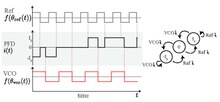
Consider the charge-pump phase-locked loop with phase-frequency detector [1]
Both the reference (Ref) and output of the VCO are square waveform signals. Without loss of generality we suppose that trailing edges of the VCO and reference signals occur when the corresponding phase reaches an integer number. The frequency of reference signal (reference frequency) is usually assumed to be constant:


where , and are a period, frequency and a phase of the reference signal.


In this section we consider PFD which is triggered by the trailing (falling) edges of the reference Ref and VCO signals. The output signal of PFD can have only three states: 0, , and .


To construct a mathematical model, we wait for a trailing edge of the reference signal and define the corresponding time instance as . Suppose that before the PFD had a certain constant state . A trailing edge of the reference signal forces the PFD to switch to a higher state, unless it is already in the state . A trailing edge of the VCO signal forces the PFD to switch to a lower state, unless it is already in the state . If both trailing edges happen at the same time, then the PFD switches to zero.


Thus, is determined by the values , , and . Similarly, is determined by , , and . Thus, is a piecewise constant and right-continuous.


The relationship between the input current and the output voltage for a proportionally integrating (perfect PI) filter based on resistor and capacitor is as follows


where is a resistance, is a capacitance, and is a capacitor charge.


The control signal adjusts the VCO frequency:

where is the VCO free-running (quiescent) frequency (i.e. for ), is the VCO gain (sensivity), and is the VCO phase.


Thus we obtain a continuous time nonlinear mathematical model of CP-PLL

with the following discontinuous piecewise constant nonlinearity

and the initial conditions . This model is nonlinear, non-autonomous, discontinuous, switching system, which is hard to analyze.

Discrete time model of Charge-Pump PLL[edit]
Following [2] [3] , we consider a discrete time model of the CP-PLL. Let . Denote by the first instant of time such that the PFD output becomes zero. If , then . Then we wait until the first trailing edge of the VCO or Ref, and denote the corresponding moment of time by . Continuing in a similar way, one obtains increasing sequences and for .


Let . Then for the is a non-zero constant (). Denote by the PFD pulse width (length of the time interval, where the PFD output is a non-zero constant), multiplied by the sign of the PFD output


If the VCO trailing edge hits before the Ref trailing edge, then and in the opposite case we have . Thus, shows how one signal lags behind another.


Zero output of PFD on the interval implies a constant filter output. Denote this constant by . We have


Following [4] , the number of parameters can be reduced to just two ( and ):


Here is a normalized phase shift and is a ratio of the VCO frequency to the reference frequency . Final system of equations describing CP-PLL without overload is the following


where

One of the advantages of described discrete time model is that it has the only one steady state at . For practical purposes, only locally (asymptotically) stable steady state, in which the loop returns after small perturbations of its state, is of interest.

Here the VCO overload conditions have the following form

If these conditions are satisfied, then the additional cases of the loop dynamics have to be taken into account [5].
--Marat Yuldashev 20:33, 29 May 2020 (UTC)
Mathematical models of APLL and Two-phase PLL[edit]

To explain the classical math model of APLL I may suggest to consider the block diagram of two-phase locked loops. For this model, the derivation of the mathematical model is straightforward (see Phase-locked_loop#Phase_domain_model_of_APLL).
Also I suggest to add APLL schemes in the signal space and in the signal’s phase space.


The models of APLL in the signal space and in the signal’s phase space are distinguished by a term with a double frequency. For the two-phase phase locked loops both models are equivalent (since the phase detector output does not contain the term with a double frequency).[6][7]
References
- ^ F. Gardner (1980). "Charge-pump phase-lock loops". IEEE Transactions on communications. 28 (11): 1849–1858.
- ^ N. Kuznetsov, M. Yuldashev, R. Yuldashev, M. Blagov, E. Kudryashova, O. Kuznetsova, and T. Mokaev (2019). "Comments on van Paemel's mathematical model of charge-pump phase-locked loop" (PDF). Differential Equations and Control Processes. 1: 109–120.
{{cite journal}}: CS1 maint: multiple names: authors list (link) - ^ N.V. Kuznetsov, A.S. Matveev, M.V. Yuldashev, R.V. Yuldashev (2020). "Nonlinear analysis of charge-pump phase-locked loop: the hold-in and pull-in ranges" (PDF). arXiv (2005.00864).
{{cite journal}}: CS1 maint: multiple names: authors list (link) - ^ P. Curran, C. Bi, and O. Feely (2013). "Analysis of a charge-pump pll: A new model". International Journal of Circuit Theory and Applications. 41 (11): 1109–1135.
{{cite journal}}: CS1 maint: multiple names: authors list (link) - ^ N.V. Kuznetsov, A.S. Matveev, M.V. Yuldashev, R.V. Yuldashev (2020). "Nonlinear analysis of charge-pump phase-locked loop: the hold-in and pull-in ranges" (PDF). arXiv (2005.00864).
{{cite journal}}: CS1 maint: multiple names: authors list (link) - ^ Leonov, G. A.; Kuznetsov, N. V.; Yuldashev, M. V.; Yuldashev, R. V. (2015). "Hold-in, pull-in, and lock-in ranges of PLL circuits: rigorous mathematical definitions and limitations of classical theory". IEEE Transactions on Circuits and Systems I: Regular Papers. 62 (10). IEEE: 2454–2464. arXiv:1505.04262. doi:10.1109/TCSI.2015.2476295.
- ^ Best, R.; Kuznetsov, N.V.; Leonov, G.A.; Yuldashev, M.V.; Yuldashev, R.V. (2016). "Tutorial on dynamic analysis of the Costas loop". IFAC Annual Reviews in Control. 42: 27–49. doi:10.1016/j.arcontrol.2016.08.003.
nk (talk) 08:40, 28 May 2020 (UTC)
A fundamental omission: How to indicate phase lock.[edit]
I won't criticise the rest because I like that the Big Maths is deferred, and the history and mechanical observation that leads into how a PLL comes to exist is good, better than I expected to find. The only general change I'd expect is to move the chunk describing the main elemental blocks of a PLL to appear right below the early identification of those blocks. The raw mechanics must always come before any finer analysis.
The big omission is the almost absent discussion of how the lock state is indicated. I assume that some degree of phase noise will always exist, so it's not an absolute state, but how much is 'good enough'? At what point is it is correct to indicate lock, and how is it done?
I ask because to reduce capture time it is often required that the oscillator be limited to a range close to the input range, so to avoid confusion of what is good and bad, it is necessary to gate the output off if it's bad! It's a simple concept to understand WHY, but there is next to no discussion of HOW. I know how to do it with a 4046 and a NAND gate, but I do not know how to explain it! :) What's the minimum need, to understand how it is agreed and indicated as 'locked'? More exactly, how do we communicate this to the devices that need to know? 81.187.19.110 (talk) 09:37, 29 May 2022 (UTC)