Miter joint: Difference between revisions
m Reverted edits by 82.32.35.66 to last revision by Old Moonraker (HG) |
Liamlllively (talk | contribs) changed to 50/50 Miter and Mitre. |
||
| Line 1: | Line 1: | ||
{{Cleanup|date=February 2008}} |
{{Cleanup|date=February 2008}} |
||
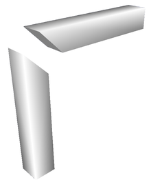
[[Image:Mitre joint square.png|thumb|220px|right|Miter joint (pieces ready to be joined).]] |
[[Image:Mitre joint square.png|thumb|220px|right|Miter joint (pieces ready to be joined).]] |
||
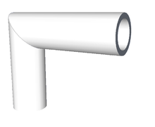
[[Image:Mitre joint pipe.png|thumb|220px|right| |
[[Image:Mitre joint pipe.png|thumb|220px|right|Mitre joint of two pipes.]] |
||
A '''mitre''' or '''miter joint''' is a joint made by [[bevel]]ling each of two parts to be joined, usually at a 45° angle, to form a corner, usually a 90° angle. It is often used in making [[picture frame]]s. |
A '''mitre''' or '''miter joint''' is a joint made by [[bevel]]ling each of two parts to be joined, usually at a 45° angle, to form a corner, usually a 90° angle. It is often used in making [[picture frame]]s. |
||
Revision as of 12:22, 19 August 2009


A mitre or miter joint is a joint made by bevelling each of two parts to be joined, usually at a 45° angle, to form a corner, usually a 90° angle. It is often used in making picture frames.
For miter joints occurring at angles other than 90°, for materials of the same width and height (i.e. pieces of a picture frame border) the proper cut angle must be determined so that the two pieces to be joined meet flush (i.e. one piece's mitered end is not longer than the adjoining piece). To find the cut angle divide the angle at which the two pieces meet by two. Technically two different cut angles are required; one for each piece, where the second angle is 90° plus the aforementioned cut angle, but due to angular limitations in common cutting implements (hand circular saws, table saws) a single angle is required and is used to cut the first piece in one direction and the second piece in the opposite direction.
When a piece is beveled at both ends, such that the two attached pieces do not lie in the same plane, a three-dimensional structure is obtained. In that case, it is also necessary to either rotate the piece along its longitudinal axis or to tilt the saw blade before beveling the second end.
When employing the miter joint to connect two pieces that have a non-circular (e.g. square) cross section, it is typically desirable to have the longitudinal edges of the joined pieces match up properly at the joint. It is always possible to close a planar structure constructed with pieces having non-circular cross section into a loop through properly matched miter joints (e.g. a picture frame). However, a three-dimensional loop from pieces with non-circular cross section need not close properly when attempting to miter it all the way round. In general, a twist occurs, causing the edges at the last joint to be misaligned[1]. A mathematical treatment of 3D mitering can be found in[2].
Woodworking and carpentry
In woodwork, it is one way of joining two pieces of moulding that meet at an angle. (Compare to the cope cut.) In carpentry it is a joint to create a pleasing look to skirting boards (base trim) and architrave around door frames and windows or any feature requiring a moulding or a border. It is a popular method of joining as it is easy and attractive. By itself, it is one of the weakest joints to choose, but it can be strengthened with a spline [2].
Piping and ducting
It is also done in pipe work, to take ducts around a corner, or in pipe organs, to fit a large bass pipe into a small space. (The same cut is used to shape of the resonators of certain reed ranks — e.g. see Great ranks and Pedal reeds of Ashton Hall organ — but only the other kind are called "mitered pipes". And, "mitered pipes" are sometimes constructed without miter cuts.
Bicycle frames
The joints of bicycle frames built with lugs are said to be mitred[3][4][5], but in this case the ends of the tubes are carefully notched or filed to fit the radius of the tube against which they are held. The joints are then brazed with brass or silver brazing rods.
See also
References
- ^ Mitering a Closed 3D Path. From The Wolfram Demonstrations Project, (Retrieved on 2009-01-20 )
- ^ Verhoeff, Tom and Koos Verhoeff, [1] "The Mathematics of Mitering and Its Artful Application, Bridges Leeuwarden: Mathematical Connections in Art, Music, and Science, Proceedings of the Eleventh Annual Bridges Conference, in The Netherlands, pp.225-234, July 2008. (Retrieved on 2009-01-20)
- ^ Brown, Sheldon. "Sheldon Brown's Glossary: Miter, Mitre". Sheldon Brown. Retrieved 2008-04-24.
- ^ "BikeCAD miter templates". Retrieved 2008-04-24.
- ^ "IHPVA Tube Mitering". Retrieved 2008-04-24.
External links
- Wooden Flue Pipes
- Miter Saw Calculator
- Miter Joint and Fold Joint. From The Wolfram Demonstrations Project, (Retrieved on 2009-01-20)
- Audels Carpenters and Builders Guide - Miter Work
