Fleming's left-hand rule for motors
This article needs additional citations for verification. (November 2011) |

Fleming's left-hand rule (for motors), and Fleming's right-hand rule (for generators) are a pair of visual mnemonics. They were originated by John Ambrose Fleming, in the late 19th century, as a simple way of working out the direction of motion in an electric motor, or the direction of electric current in an electric generator.[1]
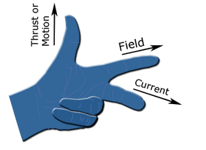
When current flows in a wire, and an external magnetic field is applied across that flow, the wire experiences a force perpendicular both to that field and to the direction of the current flow. A left hand can be held, as shown in the illustration, so as to represent three mutually orthogonal axes on the thumb, first finger and middle finger. Each finger is then assigned to a quantity (mechanical force, magnetic field and electric current). The right and left hand are used for generators and motors respectively.
Conventions
- The direction of the mechanical force is the literal one
- The direction of the magnetic field is from north to south
- The direction of the electric current is that of conventional current: from positive to negative.
Mnemonics

Several memory aids have been used in order to remember the quantity each finger represents.
First variant
- The Thumb represents the direction of the Thrust on the conductor / Motion of the Conductor
- The Fore finger represents the direction of the magnetic Field
- The Centre finger represents the direction of the Current.
Second variant
- The Thumb represents the direction of Motion resulting from the force on the conductor
- The First finger represents the direction of the magnetic Field
- The Second finger represents the direction of the Current.
Third variant
Van de Graaff's translation of Fleming's rules is the FBI rule, easily remembered because these are the initials of the Federal Bureau of Investigation.
This uses the conventional symbolic parameters of F (for Lorentz force), B (for magnetic flux density) and I (for electric current), and attributing them in that order (FBI) respectively to the thumb, first finger and second finger.
- The thumb is the force, F
- The first finger is the magnetic flux density, B
- The second finger is the electric current, I.
Of course, if the mnemonic is taught (and remembered) with a different arrangement of the parameters to the fingers, it could end up as a mnemonic that also reverses the roles of the two hands (instead of the standard left hand for motors, right hand for generators). These variants are catalogued more fully on the FBI mnemonics page.
Distinction between the right-hand and left-hand rule

Fleming's left-hand rule is used for electric motors, while Fleming's right-hand rule is used for electric generators.
Different hands need to be used for motors and generators because of the differences between cause and effect.
In an electric motor, the electric current and magnetic field exist (which are the causes), and they lead to the force that creates the motion (which is the effect), and so the left hand rule is used. In an electric generator, the motion and magnetic field exist (causes), and they lead to the creation of the electric current (effect), and so the right hand rule is used.
To illustrate why, consider that many types of electric motors can also be used as electric generators. A vehicle powered by such a motor can be accelerated up to high speed by connecting the motor to a fully charged battery. If the motor is then disconnected from the fully charged battery, and connected instead to a completely flat battery, the vehicle will decelerate. The motor will act as a generator and convert the vehicle's kinetic energy back to electrical energy, which is then stored in the battery. Since neither the direction of motion nor the direction of the magnetic field (inside the motor/generator) has changed, the direction of the electric current in the motor/generator has reversed. This follows from the second law of thermodynamics (the generator current must oppose the motor current, and the stronger current outweighs the other to allow the energy to flow from the more energetic source to the less energetic source).
The rule for motors can be recalled by remembering that "motors drive on the left in Britain". The rule for generators can be recalled by remembering that either the letters "g" and "r" is common to both "right" and "generator", or the phrase "Jenny is always right" ("Genny" being a common shortened version of Generator).
Physical basis for the rules

When electrons, or any charged particles, flow in the same direction (for example, as an electric current in an electrical conductor, such as a metal wire) they generate a cylindrical magnetic field that wraps round the conductor (as discovered by Hans Christian Ørsted).
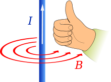
The direction of the induced magnetic field is sometimes remembered by Maxwell's corkscrew rule. That is, if the conventional current is flowing away from the viewer, the magnetic field runs clockwise round the conductor, in the same direction that a corkscrew would have to turn in order to move away from the viewer. The direction of the induced magnetic field is also sometimes remembered by the right-hand grip rule, as depicted in the illustration, with the thumb showing the direction of the conventional current, and the fingers showing the direction of the magnetic field. The existence of this magnetic field can be confirmed by placing magnetic compasses at various points round the periphery of an electrical conductor that is carrying a relatively large electric current.
If an external magnetic field is applied horizontally, so that it crosses the flow of electrons (in the wire conductor, or in the electron beam), the two magnetic fields will interact. Michael Faraday introduced a visual analogy for this, in the form of imaginary magnetic lines of force: those in the conductor form concentric circles round the conductor; those in the externally applied magnetic field run in parallel lines. If those on one side of the conductor are running (from the north to south magnetic pole) in the opposite direction to those surrounding the conductor, they will be deflected so that they pass on the other side the conductor (because magnetic lines of force cannot cross or run contrary to each other). Consequently, there will be a large number of magnetic field lines in a small space on that side of the conductor, and a dearth of them on the original side of the conductor. Since the magnetic field lines of force are no longer straight lines, but curved to run around the electrical conductor, they are under tension (like stretched elastic bands), with energy bound up in the magnetic field. Since this energetic field is now mostly unopposed, its build-up or expulsion in one direction creates — in a manner analogous to Newton's Third Law of Motion — a force in the opposite direction. Since there is only one moveable object in this system (the electrical conductor) for this force to work upon, the net effect is a physical force working to expel electrical conductor out of the externally applied magnetic field in the direction opposite to that which the magnetic flux is being redirected to — in this case (motors), if the conductor is carrying conventional current upwards, and the external magnetic field is moving away from the viewer, the physical force will work to push the conductor to the left. This is the reason for torque in an electric motor. (The electric motor is then constructed so that the expulsion of the conductor out of the magnetic field causes it be placed inside the next magnetic field, and for this switching to be continued indefinitely.)
Faraday's Law: the induced electromotive force in a conductor is directly proportional to the rate of change of the magnetic flux in the conductor.
See also
References
- ^ Fleming, John Ambrose (1902). Magnets and Electric Currents, 2nd Edition. London: E.& F. N. Spon. pp. 173–174.
{{cite book}}: Cite has empty unknown parameter:|coauthors=(help)
