
General-purpose input/output
A general-purpose input/output (GPIO) is an uncommitted digital signal pin on an integrated circuit or electronic circuit board whose behavior—including whether it acts as input or output—is controllable by the user at run time.
GPIOs have no predefined purpose and are unused by default.[1][2] If used, the purpose and behavior of a GPIO is defined and implemented by the designer of higher assembly-level circuitry: the circuit board designer in the case of integrated circuit GPIOs, or system integrator in the case of board-level GPIOs.
Integrated circuit GPIOs
Integrated circuit (IC) GPIOs are implemented in a variety of ways. Some ICs provide GPIOs as a primary function whereas others include GPIOs as a convenient "accessory" to some other primary function. Examples of the former include the Intel 8255, which interfaces 24 GPIOs to a parallel bus, and various GPIO "expander" ICs, which interface GPIOs to serial buses such as I²C and SMBus. An example of the latter is the Realtek ALC260 IC, which provides eight GPIOs in addition to its primary function of audio codec.
Microcontroller ICs typically include GPIOs. Depending on the application, a microcontroller's GPIOs may comprise its primary interface to external circuitry or they may be just one type of I/O used among several, such as analog I/O, counter/timer, and serial communication.
In some ICs, particularly microcontrollers, a GPIO pin may be capable of alternate functions. Often in such cases, it is necessary to configure the pin to operate as a GPIO (vs. its alternate functions) in addition to configuring the GPIO's behavior. Some microcontroller devices (e.g., Microchip dsPIC33 family) incorporate internal signal routing circuitry that allows GPIOs to be programmatically mapped to device pins. FPGAs extend this capability by allowing GPIO pin mapping, instantiation and architecture to be programmatically controlled.
-
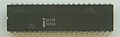 Parallel bus interface to 24 GPIOs (Intel 8255)
 -
 A "versatile interface adapter", which combines 20 GPIOs with other general-purpose interfaces (MOS Technology 6522)
 -
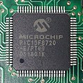 A microcontroller with 29 remappable GPIOs (Microchip Technology PIC24FJ256)

Board-level GPIOs
Many circuit boards expose board-level GPIOs to external circuitry through integrated electrical connectors. Typically, each such GPIO is accessible via a dedicated connector pin.
Like IC-based GPIOs, some boards merely include GPIOs as a convenient, auxiliary resource that augments the board's primary function, whereas in other boards the GPIOs are the central, primary function of the board. Some boards, which typically are classified as multi-function I/O boards, are a combination of both; such boards provide GPIOs along with other types of general-purpose I/O. GPIOs are also found on embedded controller boards such as Arduino, BeagleBone and Raspberry Pi.[3]
Board-level GPIOs are often endowed with capabilities which typically are not found in IC-based GPIOs. For example, schmitt-trigger inputs, high-current output drivers, optical isolators, or combinations of these may be used to buffer and condition the GPIO signals and to protect board circuitry. Also, higher-level functions are sometimes implemented, such as input debounce, input signal edge detection, and pulse-width modulation (PWM) output.
-
 Network router with three GPIOs (Banana Pi R1)
 -
 GPIO interface for Hewlett-Packard Series 80 computers (HP 82940A)
 -
 Ethernet interface to 48 GPIOs (Sensoray 2410)


Usage
GPIOs are used in a diverse variety of applications, limited only by the electrical and timing specifications of the GPIO interface and the ability of software to interact with GPIOs in a sufficiently timely manner.
GPIOs typically employ standard logic levels and cannot supply significant current to output loads. When followed by an appropriate high-current output buffer (or mechanical or solid-state relay), a GPIO may be used to control high-power devices such as lights, solenoids, heaters, and motors (e.g., fans and blowers). Similarly, an input buffer, relay or opto-isolator is often used to translate an otherwise incompatible signal (e.g., high voltage) to the logic levels required by a GPIO.
Integrated circuit GPIOs are commonly used to control or monitor other circuitry (including other ICs) on a board. Examples of this include enabling and disabling the operation of (or power to) other circuitry, reading the states of on-board switches and configuration shunts, and driving LED status indicators. In the latter case, a GPIO can, in many cases, supply enough output current to directly power an LED without using an intermediate buffer.
Multiple GPIOs are sometimes used together as a bit-banged communication interface. For example, two GPIOs may be used to implement a serial communication bus such as I²C, and four GPIOs can be used to implement an SPI bus; these are typically used to facilitate serial communication with ICs and other devices which have compatible serial interfaces, such as sensors (e.g., temperature sensors, pressure sensors, accelerometers) and motor controllers. Taken to the extreme, this technique may be used to implement an entire parallel bus, thus allowing communication with bus-oriented ICs or circuit boards.
Although GPIOs are fundamentally digital in nature, they are often used to control linear processes. For example, a GPIO may be used to control motor speed, light intensity, or temperature. Typically, this is accomplished via PWM, in which the duty cycle of the GPIO output signal determines the effective magnitude of the process control signal. For example, when controlling light intensity, the light may be dimmed by reducing the GPIO duty cycle. Some linear processes require a linear control voltage; in such cases it may be feasible to connect a GPIO -- which is operated as a PWM output -- to an RC filter to create a simple and inexpensive digital-to-analog converter.
Implementation
GPIO interfaces vary widely. In some cases, they are simple—a group of pins that can switch as a group to either input or output. In others, each pin can be set up to accept or source different logic voltages, with configurable drive strengths and pull ups/downs. Input and output voltages are typically—though not always—limited to the supply voltage of the device with the GPIOs, and may be damaged by greater voltages.
A GPIO pin's state may be exposed to the software developer through one of a number of different interfaces, such as a memory mapped peripheral, or through dedicated IO port instructions. Some GPIOs have 5 V tolerant inputs: even when the device has a low supply voltage (such as 2 V), the device can accept 5 V without damage.
A GPIO port is a group of GPIO pins (typically 8 GPIO pins) arranged in a group and controlled as a group.[4]
GPIO capabilities may include:[2]
- GPIO pins can be configured to be input or output[4]
- GPIO pins can be enabled/disabled
- Input values are readable (typically high or low)
- Output values are writable/readable
- Input values can often be used as IRQs (typically for wakeup events)
See also
References
- ^ White, Jon, ed. (2016). Raspberry Pi - The Complete Manual (7 ed.). Imagine Publishing. p. 36. ISBN 978-1785463709.
- ^ a b "General Purpose Input/Output". Oracle® Java ME Embedded Developer's Guide (8 ed.). Oracle Corporation. 2014.
- ^ "GPIO - Raspberry Pi Documentation". Raspberry Pi Foundation. Retrieved 3 November 2016.
- ^ a b Balachandran, Sasang (2009). General Purpose Input/Output (GPIO) (PDF). Michigan State University College of Engineering.