
Tyer's Electric Train Tablet
The examples and perspective in this article may not represent a worldwide view of the subject. (August 2008) |
Tyer's Electric Train Tablet system is a form of railway signalling for single line railways used in several countries; it was first devised in Great Britain by engineer Edward Tyer after the Thorpe rail accident of 1874, which left 21 people dead.[1] It was used in New Zealand for close to 100 years until June 1994. The system used a hard disk called a tablet, a form of token.
The purpose of the system was to use the tablet as a physical guarantee to the traincrew that their train had exclusive right of way on the single-line section. Without it, they could not proceed beyond the section signal which protected entry to the next section of the single line.
With advances in electrical locking of the lever frame within the signal box, the tablet instrument also electrically locked the section signal lever. That was marked with a white stripe on the red background.
Construction[edit]

An instrument was placed at each end of the single-track section that they were to control. They were connected together electrically in such a way that operation of one would depend on operations carried out using the other.
There were various incarnations of instruments developed by Tyer & Co. Below are the more commonly found ones:
The Tyer's no. 7 tablet instrument consists of a wooden case, on top of which is a metal slide, a switch plunger, a bell plunger and an electric current indicator. On the front is an indicator which may show any of three indications: "Line Closed"; "Train Approaching" and "Train on Line". Below this there is a second slide, which has three positions: fully home, withdrawn half way, and fully withdrawn. The three indications correspond to the three positions of the slide. The case contains several tablets; they are removed from the instrument using the bottom slide, and replaced using the top slide. The instrument was so constructed that if a tablet had been withdrawn from either instrument of a pair, no further tablets could be withdrawn until the withdrawn tablet had been placed either in the other instrument, or in the same instrument from which it had been withdrawn.[2]
The Tyer's no. 6 tablet instrument is cast iron framed that has a movable drawer at the front which issues and receives the tablets. On the left hand side is a lever to reseat the tablet when it is replaced into the magazine. It has wooden side cheeks to access the complicated mechanism and a tombstone shaped wooden case on the top which houses the bell plunger, commutator and the tablet indicators for up and down trains. At the very top was the galvanometer. The signalling bell associated with the machine is separate so could be located on the block shelf or wall mounted above the instrument.
Tablets[edit]
Tablets are in the form of a disc made of metal or fibre (with a gunmetal weight at the top of the magazine), engraved with the names of the stations between which it is valid, and also provided with notches (also called configurations) or other indentations to ensure that it would fit only one pair of instruments. They were often painted in distinctive colours as an additional visual identification in areas where consecutive sections could each be controlled using the same type of instrument. The diameter of the tablets varied between the different patterns of instrument: those for the No 1 were the largest, the smallest were for the No 5 and No 7, whilst the Nos 2,3,4 and 6 all used tablets about 4.5 inches (110 mm) in diameter.
Operation[edit]

The system required each station at the end of each section to be staffed; the staff member would communicate with the staff member at the other end of the section with a bell code to release a tablet.[2][3][4]
To release a tablet at station A to send a train to station B:
- Both machines must be in a closed state
- Operator at station A sends a bell code to station B asking if line is clear for the train
- If clear, operator at station B will repeat the bell code to acknowledge
- Station A operator holds down the bell plunger
- Station B operator presses his/her switch plunger with one hand, and with the other pulls out the bottom slide half-way; the instrument now shows a "Train Approaching" indication
- Station B operator holds down the bell plunger
- Station A operator presses his/her switch plunger with one hand, and with the other pulls the bottom slide to its full extent; the instrument now shows a "Train on Line" indication and releases a tablet from the lower slide
- Station A operator hands the tablet to the driver of the train heading to station B
To close up each machine once the train has arrived at station B from station A:
- The train driver hands the tablet to station B operator
- Station B operator draws out the top slide, places the tablet in it, and closes the top and then the bottom slide; the instrument now shows a "Line Closed" indication
- Station B operator sends a bell code to station A (denoting "Train out of Section"), holding the plunger down on the last stroke
- Station A operator holds down his switch plunger, and closes the bottom slide; the instrument now shows a "Line Closed" indication
- Both machines are now in closed states ready for the process to start again for another train
The original Tyer's No. 1 instrument was a non-restoring design, as were the subsequent Nos 2 and 3 types. Once the tablet had been removed, it had to travel through the single line section and be replaced in its companion instrument to release the section again. This meant that should a train failure occur in the single line section or a shunt beyond station limits, the tablet had to travel to the receiving instrument by foot or horse. However, there was a way in which a shunt could be performed without removing the tablet. This was achieved by a very similar means of the staff and ticket working system.
The later No 6 model however was a restoring design, which enabled the tablet to be placed back into the issuing instrument for shunting out of station limits. This increased flexibility and did not compromise safety. It also dispensed with the written authority in the staff and ticket system. Many No 1 instruments were modified with No 6 components to make them capable of restoring also.
Areas of use[edit]


The Great Western Railway used the Tyer's No. 7 electric train tablet instrument at several locations, including the Bampton to Witney section.[5]
Sri Lanka Railways is currently using this system at several locations, including the Kelani Valley line between Maradana and Avissawella in the Colombo District.
In Japan, carbon-copies of the Tyer's No. 7 tablet instrument were used on many single lines and some are still in use or kept on display at many rural stations.
The Tyer's No. 6 tablet instrument was far more widespread in the UK and was adopted by most railway companies on single line installations. However, when the Tyer's No. 9 key token instrument was patented 40 years later in 1912, it began to replace the No. 6 due to it being compact, easier to use and had far fewer moving parts to service and repair.[citation needed]
On Britain's national network the use of Tyer's system is now almost extinct, with most lengthy single track lines having been converted to more modern systems such as Tokenless Block or Radio Electronic Token Block. However, as of 2015[update], the Tyer Electric Token Block, using No 7 instruments and coloured perspex tablets, remains in use on the Stranraer Line, between Girvan and Dunragit.
Tyer's tablet working in New Zealand[edit]

Tyer's Tablet working using the No 7 system was used in New Zealand from 1901, as most lines apart from sections near the main centres were single-track. The tablets were generally of fibre, and were originally exchanged by hand using cane slings. Later (safer) mechanical exchangers were used. The Rakaia railway accident of 1899 had exposed the need for improvements to signalling and train braking.[6]
Single-track sections of the North Island Main Trunk between Auckland and Wellington were controlled by Tyer's No 7 system; most of the line was single-track. Each of the stations for the 94 tablet sections required three tablet porters who each worked a 56-hour week for continuous coverage. Hence each station (many in isolated locations) required at least four houses, for the stationmaster and three porters. From 1938 to 1966 Centralised Traffic Control (C.T.C.) gradually replaced the Tablet system on the NIMT.[7]
The last tablet used on the New Zealand Railways was to allow train 1602 (Wellington – Masterton morning Wairarapa Connection) to travel between Featherston and Masterton on the Wairarapa Line on Monday 4 July 1994. Even though the Masterton to Woodville tablet sections survived a few days longer, trains ran on a safe all where Train Control could allow a train to run without a tablet.
Heritage railways and museums[edit]
Today the tablet system lives on in many heritage railways and museums either as static / operational / interactive displays or as part of the heritage railway signalling system
Heritage railways[edit]
- Swanage Railway, Dorset, England
- Ferrymead Railway, Christchurch, New Zealand
- Silver Stream Railway, Wellington, New Zealand
- Glenbrook Vintage Railway, Auckland, New Zealand
- Kent & East Sussex Railway, Tenterden Town, England
- North Norfolk Railway, England[8]
Railway museums[edit]
- Carterton Community & Railway Museum, Carterton railway station, New Zealand
- Glenfinnan Station Museum, Scotland
- Fell Engine Museum, Featherston, New Zealand
- Kadugannawa railway museum, Sri Lanka
Other[edit]
- New Zealand Railway and Locomotive Society Ava Archive
- Pahiatua Railcar Society, Pahiatua Railway Station, New Zealand
- Helensville Railway Station Trust, New Zealand[9]
- Papatoetoe Railway Station Preservation Trust, New Zealand
- Taumarunui Rail Action Group, New Zealand
- Ormondville Railway Station, New Zealand[10]
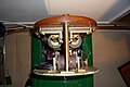
Internal workings[edit]
Below are a few photographs of the internal workings. This particular instrument has had the electric line clear addition and restoring functions added at a later date. It also carries the original plates by the plunger and commutator which were often removed.
-
 Left side showing the tablet restoring lever, line clear release and the coils
 -
 The top portion where the commutator and indicator mechanism and circuits are housed
 -
 Top view showing the indicator coils and part of the commutator mechanism
 -
 Detailed photograph of the commutator mechanism and the push rods that interact with the indicators
 -
 The right side showing the tablet replacing mechanism and rods to the tablet status indicators


Accidents[edit]
Before tokens[edit]
- Menheniot accident 1873. The verbal order given to a train guard to depart in one direction was overheard by the guard of the train waiting to leave on the single line in the other direction; he mistakenly ordered his train to leave, resulting in a head-on collision.[11]
After tokens[edit]
- Abermule
- Oswestry: Head on collision on 18 January 1918. The drivers of both engines held the correct token, issued as they started their respective journeys. The electrical circuits linking the machines at either end were also used for telephones and, together with a possible line fault caused by bad weather, allowed the issue of two tokens at the same time.[12]
References[edit]
- ^ Faith 2000, p. 44.
- ^ a b Vaughan 1984, p. 121.
- ^ Pierre 1981, pp. 215–220.
- ^ Heine 2000, pp. 85–89.
- ^ Vaughan 1984, p. 102.
- ^ Heine 2000, pp. 85–98.
- ^ Pierre 1981, pp. 214–222.
- ^ "Instruments etc". trainweb.org. Retrieved 11 September 2021.
- ^ "Helensville Railway Station Precinct".
- ^ "Ormondville Railway Station".
- ^ Yolland, William (30 January 1874). "Accident Returns: Extract for the Accident at Menheniot - St Germans on 2nd December 1873" (PDF). Railways Archive. Board of Trade.
- ^ Pringle, J. W. (23 April 2018). "Cambrian Railway" (PDF). Board of Trade.
Further reading[edit]
- Cameron, W N (1976). A Line of Railway: The Railway Conquest of the Rimutakas. Wellington: New Zealand Railway and Locomotive Society. ISBN 0-908573-00-6.
- Faith, Nicholas (2000). Derail: Why Trains Crash. London: Channel 4/Macmillan. ISBN 0-7522-7165-2.
- Heine, Richard W. (2000). Semaphore to CTC: Signalling and train working in New Zealand, 1863-1993. Wellington: New Zealand Railway and Locomotive Society. ISBN 0-908573-76-6.
- Pierre, W.A. (Bill) (1981). North Island Main Trunk: An Illustrated History. Auckland: A.H. & A.W. Reed. ISBN 0-589-01316-5.
- Vaughan, Adrian (1984) [1973]. A Pictorial Record of Great Western Signalling (2nd ed.). Poole: Oxford Publishing Co. ISBN 0-86093-346-6.
- Yonge, John (1993). New Zealand Railway and Tramway Atlas (4th edn). Exeter, England: The Quail Map Co. ISBN 0-900609-92-3.