
Francis turbine


The Francis turbine is a type of water turbine. It is an inward-flow reaction turbine that combines radial and axial flow concepts. Francis turbines are the most common water turbine in use today, and can achieve over 95% efficiency.[1]
The process of arriving at the modern Francis runner design took from 1848 to approximately 1920.[1] It became known as the Francis turbine around 1920, being named after British-American engineer James B. Francis who in 1848 created a new turbine design.[1]
Francis turbines are primarily used for producing electricity. The power output of the electric generators generally ranges from just a few kilowatts up to 1000 MW, though mini-hydro installations may be lower. The best performance is seen when the head height is between 100–300 metres (330–980 ft).[2] Penstock diameters are between 1 and 10 m (3.3 and 32.8 ft). The speeds of different turbine units range from 70 to 1000 rpm. A wicket gate around the outside of the turbine's rotating runner controls the rate of water flow through the turbine for different power production rates. Francis turbines are usually mounted with a vertical shaft, to isolate water from the generator. This also facilitates installation and maintenance.[citation needed]
Development[edit]


.jpg)
Water wheels of different types have been used for more than 1,000 years to power mills of all types, but they were relatively inefficient. Nineteenth-century efficiency improvements of water turbines allowed them to replace nearly all water wheel applications and compete with steam engines wherever water power was available. After electric generators were developed in the late 1800s, turbines were a natural source of generator power where potential hydropower sources existed.
In 1826 the French engineer Benoit Fourneyron developed a high-efficiency (80%) outward-flow water turbine. Water was directed tangentially through the turbine runner, causing it to spin. Another French engineer, Jean-Victor Poncelet, designed an inward-flow turbine in about 1820 that used the same principles. S. B. Howd obtained a US patent in 1838 for a similar design.
In 1848 James B. Francis, while working as head engineer of the Locks and Canals company in the water wheel-powered textile factory city of Lowell, Massachusetts,[3] improved on these designs to create more efficient turbines. He applied scientific principles and testing methods to produce a very efficient turbine design. More importantly, his mathematical and graphical calculation methods improved turbine design and engineering. His analytical methods allowed the design of high-efficiency turbines to precisely match a site's water flow and pressure (water head).
Components[edit]
A Francis turbine consists of the following main parts:
Spiral casing: The spiral casing around the runner of the turbine is known as the volute casing or scroll case. Throughout its length, it has numerous openings at regular intervals to allow the working fluid to impinge on the blades of the runner. These openings convert the pressure energy of the fluid into kinetic energy just before the fluid impinges on the blades. This maintains a constant velocity despite the fact that numerous openings have been provided for the fluid to enter the blades, as the cross-sectional area of this casing decreases uniformly along the circumference.
Guide and stay vanes: The primary function of the guide and stay vanes is to convert the pressure energy of the fluid into kinetic energy. It also serves to direct the flow at design angles to the runner blades.
Runner blades: Runner blades are the heart of any turbine. These are the centers where the fluid strikes and the tangential force of the impact produces torque causing the shaft of the turbine to rotate. Close attention to design of blade angles at inlet and outlet is necessary, as these are major parameters affecting power production.
Draft tube: The draft tube is a conduit that connects the runner exit to the tail race where the water is discharged from the turbine. Its primary function is to reduce the velocity of discharged water to minimize the loss of kinetic energy at the outlet. This permits the turbine to be set above the tail water without appreciable drop of available head.
Theory of operation[edit]

The Francis turbine is a type of reaction turbine, a category of turbine in which the working fluid comes to the turbine under immense pressure and the energy is extracted by the turbine blades from the working fluid. A part of the energy is given up by the fluid because of pressure changes occurring on the blades of the turbine, quantified by the expression of degree of reaction, while the remaining part of the energy is extracted by the volute casing of the turbine. At the exit, water acts on the spinning cup-shaped runner features, leaving at low velocity and low swirl with very little kinetic or potential energy left. The turbine's exit tube is shaped to help decelerate the water flow and recover the pressure.
-
 Francis turbine (exterior view) attached to a generator
 -
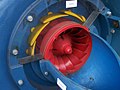 Cut-away view, with wicket gates (yellow) at minimum flow setting
 -
 Cut-away view, with wicket gates (yellow) at full flow setting


Blade efficiency[edit]

Usually the flow velocity (velocity perpendicular to the tangential direction) remains constant throughout, i.e. Vf1=Vf2 and is equal to that at the inlet to the draft tube. Using the Euler turbine equation, E/m=e=Vw1U1, where e is the energy transfer to the rotor per unit mass of the fluid. From the inlet velocity triangle,

and

Therefore

The loss of kinetic energy per unit mass at the outlet is Vf22/2. Therefore, neglecting friction, the blade efficiency becomes

i.e.

Degree of reaction[edit]

Degree of reaction can be defined as the ratio of pressure energy change in the blades to total energy change of the fluid.[4] This means that it is a ratio indicating the fraction of total change in fluid pressure energy occurring in the blades of the turbine. The rest of the changes occur in the stator blades of the turbines and the volute casing as it has a varying cross-sectional area. For example, if the degree of reaction is given as 50%, that means that half of the total energy change of the fluid is taking place in the rotor blades and the other half is occurring in the stator blades. If the degree of reaction is zero it means that the energy changes due to the rotor blades is zero, leading to a different turbine design called the Pelton Turbine.

The second equality above holds, since discharge is radial in a Francis turbine. Now, putting in the value of 'e' from above and using (as )


Application[edit]

Francis turbines may be designed for a wide range of heads and flows. This versatility, along with their high efficiency, has made them the most widely used turbine in the world. Francis type units cover a head range from 40 to 600 m (130 to 2,000 ft), and their connected generator output power varies from just a few kilowatts up to 1000 MW. Large Francis turbines are individually designed for each site to operate with the given water flow and water head at the highest possible efficiency, typically over 90% (to 99%[5]).
In contrast to the Pelton turbine, the Francis turbine operates at its best completely filled with water at all times. The turbine and the outlet channel may be placed lower than the lake or sea level outside, reducing the tendency for cavitation.
In addition to electrical production, they may also be used for pumped storage, where a reservoir is filled by the turbine (acting as a pump) driven by the generator acting as a large electrical motor during periods of low power demand, and then reversed and used to generate power during peak demand. These pump storage reservoirs act as large energy storage sources to store "excess" electrical energy in the form of water in elevated reservoirs. This is one of a few methods that allow temporary excess electrical capacity to be stored for later utilization.
See also[edit]
- Draft tube
- Evolution from Francis turbine to Kaplan turbine
- Hydropower
- Jonval turbine
- Kaplan turbine
- Pelton wheel
- Sensor fish, a device used to study the impact of fish travelling through Francis and Kaplan turbines
Citations[edit]
- ^ a b c Lewis, B J; Cimbala, J M; Wouden, A M (2014-03-01). "Major historical developments in the design of water wheels and Francis hydroturbines". IOP Conference Series: Earth and Environmental Science. 22 (1): 012020. Bibcode:2014E&ES...22a2020L. doi:10.1088/1755-1315/22/1/012020. ISSN 1755-1315.
 This article incorporates text from this source, which is available under the CC BY 3.0 license.
- ^ Paul Breeze, Power Generation Technologies (Third Edition), 2019
- ^ "Lowell Notes – James B. Francis" (PDF). National Park Service. Archived from the original (PDF) on 2016-03-10.
- ^ Bansal, RK (2010). A textbook of fluid mechanics and hydraulic machines (Revised ninth ed.). India: Laxmi publications. pp. 880–883.
- ^ L. Suo, ... H. Xie, in Comprehensive Renewable Energy, 2012
General bibliography[edit]
- Layton, Edwin T. From Rule of Thumb to Scientific Engineering: James B. Francis and the Invention of the Francis Turbine. NLA Monograph Series. Stony Brook, NY: Research Foundation of the State University of New York, 1992. OCLC 1073565482.
- S. M. Yahya, page number 13, fig. 1.14.[full citation needed]
| Hydroelectricity generation |  | |
|---|---|---|
| Hydroelectricity equipment | ||