Punched tape

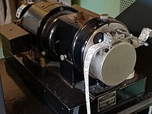

Punched tape or perforated paper tape is a form of data storage device that consists of a long strip of paper through which small holes are punched. It was developed from and was subsequently used alongside punched cards, the difference being that the tape is continuous.
Punched cards, and chains of punched cards, were used for control of looms in the 18th century. Use for telegraphy systems started in 1842. Punched tapes were used throughout the 19th and for much of the 20th centuries for programmable looms, teleprinter communication, for input to computers of the 1950s and 1960s, and later as a storage medium for minicomputers and CNC machine tools. During the Second World War, high-speed punched tape systems using optical readout methods were used in code breaking systems. Punched tape was used to transmit data for manufacture of read-only memory chips.
History
[edit]
Perforated paper tapes were first used by Basile Bouchon in 1725 to control looms. However, the paper tapes were expensive to create, fragile, and difficult to repair. By 1801, Joseph Marie Jacquard had developed machines to create paper tapes by tying punched cards in a sequence for Jacquard looms. The resulting paper tape, also called a "chain of cards", was stronger and simpler both to create and to repair. This led to the concept of communicating data not as a stream of individual cards, but as one "continuous card" (or tape). Paper tapes constructed from punched cards were widely used throughout the 19th century for controlling looms. Many professional embroidery operations still refer to those individuals who create the designs and machine patterns as punchers even though punched cards and paper tape were eventually phased out in the 1990s.
In 1842, a French patent by Claude Seytre described a piano playing device that read data from perforated paper rolls. By 1900, wide perforated music rolls for player pianos were used to distribute popular music to mass markets.

In 1846, Alexander Bain used punched tape to send telegrams. This technology was adopted by Charles Wheatstone in 1857 for the Wheatstone system used for the automated preparation, storage and transmission of data in telegraphy.[1][2]
In the 1880s, Tolbert Lanston invented the Monotype typesetting system, which consisted of a keyboard and a composition caster. The tape, punched with the keyboard, was later read by the caster, which produced lead type according to the combinations of holes in up to 31 positions. The tape reader used compressed air, which passed through the holes and was directed into certain mechanisms of the caster. The system went into commercial use in 1897 and was in production well into the 1970s, undergoing several changes along the way.
Modern use
[edit]In the 21st century, punched tape is obsolete except among hobbyists. In computer numerical control (CNC) machining applications, though paper tape has been superseded by digital memory, some modern systems still measure the size of stored CNC programs in feet or meters, corresponding to the equivalent length if the data were actually punched on paper tape.[3]
Formats
[edit]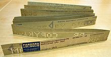

Data was represented by the presence or absence of a hole at a particular location. Tapes originally had five rows of holes for data across the width of the tape. Later tapes had more rows. A 1944 electro-mechanical programmable calculating machine, the Automatic Sequence Controlled Calculator or Harvard Mark I, used paper tape with 24 rows,[4] The IBM Selective Sequence Electronic Calculator (SSEC) used paper tape with 74 rows.[5] Australia's 1951 electronic computer, CSIRAC, used 3-inch (76 mm) wide paper tape with twelve rows.[6]
A row of smaller sprocket holes was always punched to be used to synchronize tape movement. Originally, this was done using a wheel with radial teeth called a sprocket wheel. Later, optical readers made use of the sprocket holes to generate timing pulses. The sprocket holes were slightly closer to one edge of the tape, dividing the tape into unequal widths, to make it unambiguous which way to orient the tape in the reader. The bits on the narrower width of the tape were generally the least significant bits when the code was represented as numbers in a digital system.[7]
Materials
[edit]Many early machines used oiled paper tape, which was pre-impregnated with a light machine oil, to lubricate the reader and punch mechanisms. The oil impregnation usually made the paper somewhat translucent and slippery, and excess oil could transfer to clothing or any surfaces it contacted. Later optical tape readers often specified non-oiled opaque paper tape, which was less prone to depositing oily debris on the optical sensors and causing read errors. Another innovation was fanfold paper tape, which was easier to store compactly and less prone to tangling, as compared to rolled paper tape.
For heavy-duty or repetitive use, polyester Mylar tape was often used. This tough, durable plastic film was usually thinner than paper tapes, but could still be used in many devices originally designed for paper media. The plastic tape was sometimes transparent, but usually was aluminized to make it opaque enough for use in high-speed optical readers.
Dimensions
[edit]Tape for punching was usually 0.00394 inches (0.100 mm) thick. The two most common widths were 11⁄16 inch (17 mm) for five bit codes, and 1 inch (25 mm) for tapes with six or more bits. Hole spacing was 0.1 inches (2.5 mm) in both directions. Data holes were 0.072 inches (1.8 mm) in diameter; sprocket feed holes were 0.046 inches (1.2 mm).[8]
Chadless tape
[edit]
Most tape-punching equipment used solid circular punches to create holes in the tape. This process created "chad", or small circular pieces of paper. Managing the disposal of chad was an annoying and complex problem, as the tiny paper pieces had a tendency to escape containment and to interfere with the other electromechanical parts of the teleprinter equipment. Chad from oiled paper tape was particularly problematic, as it tended to clump and build up, rather than flowing freely into a collection container.
A variation on the tape punch was a device called a Chadless Printing Reperforator. This machine would punch a received teleprinter signal into tape and print the message on it at the same time, using a printing mechanism similar to that of an ordinary page printer. The tape punch, rather than punching out the usual round holes, would instead punch little U-shaped cuts in the paper, so that no chad would be produced; the "hole" was still filled with a little paper trap-door. By not fully punching out the hole, the printing on the paper remained intact and legible. This enabled operators to read the tape without having to decipher the holes, which would facilitate relaying the message on to another station in the network. Also, there was no "chad box" to empty from time to time.
A disadvantage to this technology was that, once punched, chadless tape did not roll up well for storage, because the protruding flaps of paper would catch on the next layer of tape so it could not be coiled up tightly. Another disadvantage that emerged in time, was that there was no reliable way to read chadless tape in later high-speed readers which used optical sensing. However, the mechanical tape readers used in most standard-speed equipment had no problem with chadless tape, because they sensed the holes by means of blunt spring-loaded mechanical sensing pins, which easily pushed the paper flaps out of the way.
Encoding
[edit]
Text was encoded in several ways. The earliest standard character encoding was Baudot, which dates back to the 19th century and had five holes. The Baudot code was superseded by modified five-hole codes such as the Murray code (which added carriage return and line feed) which was developed into the Western Union code which was further developed into the International Telegraph Alphabet No. 2 (ITA 2), and a variant called the American Teletypewriter code (USTTY).[9] Other standards, such as Teletypesetter (TTS), FIELDATA and Flexowriter, had six holes. In the early 1960s, the American Standards Association led a project to develop a universal code for data processing, which became the American Standard Code for Information Interchange (ASCII). This seven-level code was adopted by some teleprinter users, including AT&T (Teletype). Others, such as Telex, stayed with the earlier codes.
Applications
[edit]Communications
[edit]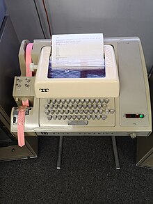

Punched tape was used as a way of storing messages for teletypewriters. Operators typed in the message to the paper tape, and then sent the message at the maximum line speed from the tape. This permitted the operator to prepare the message "off-line" at the operator's best typing speed, and permitted the operator to correct any error prior to transmission. An experienced operator could prepare a message at 135 words per minute (WPM) or more for short periods.
The line typically operated at 75 WPM, but it operated continuously. By preparing the tape "off-line" and then sending the message with a tape reader, the line could operate continuously rather than depending on continuous "on-line" typing by a single operator. Typically, a single 75 WPM line supported three or more teletype operators working offline. Tapes punched at the receiving end could be used to relay messages to another station. Large store and forward networks were developed using these techniques.
Paper tape could be read into computers at up to 1,000 characters per second.[10] In 1963, a Danish company called Regnecentralen introduced a paper tape reader called RC 2000 that could read 2,000 characters per second; later they increased the speed further, up to 2,500 cps. As early as World War II, the Heath Robinson tape reader, used by Allied codebreakers, was capable of 2,000 cps while Colossus could run at 5,000 cps using an optical tape reader designed by Arnold Lynch.
Minicomputers
[edit]
When the first minicomputers were being released, most manufacturers turned to the existing mass-produced ASCII teleprinters (primarily the Teletype Model 33, capable of ten ASCII characters per second throughput) as a low-cost solution for keyboard input and printer output. The commonly specified Model 33 ASR included a paper tape punch/reader, where ASR stands for "Automatic Send/Receive" as opposed to the punchless/readerless KSR – Keyboard Send/Receive and RO – Receive Only models. As a side effect, punched tape became a popular medium for low-cost minicomputer data and program storage, and it was common to find a selection of tapes containing useful programs in most minicomputer installations. Faster optical readers were also common.
Binary data transfer to or from these minicomputers was often accomplished using a doubly encoded technique to compensate for the relatively high error rate of punches and readers. The low-level encoding was typically ASCII, further encoded and framed in various schemes such as Intel Hex, in which a binary value of "01011010" would be represented by the ASCII characters "5A". Framing, addressing and checksum (primarily in ASCII hex characters) information helped with error detection. Efficiencies of such an encoding scheme are on the order of 35–40% (e.g., 36% from 44 8-bit ASCII characters being needed to represent sixteen bytes of binary data per frame).
Computer-aided manufacturing
[edit]
In the 1970s, computer-aided manufacturing equipment often used paper tape. A paper tape reader was smaller and less expensive than Hollerith card or magnetic tape readers, and the medium was reasonably reliable in a manufacturing environment. Paper tape was an important storage medium for computer-controlled wire-wrap machines, for example.
Premium black waxed and lubricated long-fiber papers, and Mylar film tape were developed so that heavily used production tapes would last longer.
Data transfer for ROM and EPROM programming
[edit]In the 1970s through the early 1980s, paper tape was commonly used to transfer binary data for incorporation in either mask-programmable read-only memory (ROM) chips or their erasable counterparts EPROMs. A significant variety of encoding formats were developed for use in computer and ROM/EPROM data transfer.[11] Encoding formats commonly used were primarily driven by those formats that EPROM programming devices supported and included various ASCII hex variants as well as a number of proprietary formats.
A much more primitive as well as a much longer high-level encoding scheme was also used, BNPF (Begin-Negative-Positive-Finish),[12][13] also written as BPNF (Begin-Positive-Negative-Finish).[14] In BNPF encoding, a single byte (8 bits) would be represented by a highly redundant character framing sequence starting with a single uppercase ASCII "B", eight ASCII characters where a "0" would be represented by a "N" and a "1" would be represented by a "P", followed by an ending ASCII "F".[12][14][13] These ten-character ASCII sequences were separated by one or more whitespace characters, therefore using at least eleven ASCII characters for each byte stored (9% efficiency). The ASCII "N" and "P" characters differed in four bit positions, providing excellent protection from single punch errors. Alternative schemes named BHLF (Begin-High-Low-Finish) and B10F (Begin-One-Zero-Finish) were also available where either "L" and "H" or "0" and "1" were also available to represent data bits,[15] but in both of these encoding schemes, the two data-bearing ASCII characters differ in only one bit position, providing very poor single punch error detection.
Cash registers
[edit]NCR of Dayton, Ohio, made cash registers around 1970 that would punch paper tape. Sweda made similar cash registers around the same time. The tape could then be read into a computer and not only could sales information be summarized, billings could be done on charge transactions. The tape was also used for inventory tracking, recording department and class numbers of items sold.
Newspaper industry
[edit]Punched paper tape was used by the newspaper industry until the mid-1970s or later. Newspapers were typically set in hot lead by devices like Linotype machines. With the wire services coming into a device that would punch paper tape, rather than the Linotype operator having to retype all the incoming stories, the paper tape could be put into a paper tape reader on the Linotype and it would create the lead slugs without the operator re-typing the stories. This also allowed newspapers to use devices, such as the Friden Flexowriter, to convert typing to lead type via tape. Even after the demise of Linotype and hot lead typesetting, many early phototypesetter devices utilized paper tape readers.
If an error was found at one position on the six-level tape, that character could be turned into a null character to be skipped by punching out the remaining non-punched positions with what was known as a “chicken plucker". It looked like a strawberry stem remover that, pressed with thumb and forefinger, could punch out the remaining positions, one hole at a time.
Cryptography
[edit]
Vernam ciphers were invented in 1917 to encrypt teleprinter communications using a key stored on paper tape. During the last third of the 20th century, the National Security Agency (NSA) used punched paper tape to distribute cryptographic keys. The eight-level paper tapes were distributed under strict accounting controls and read by a fill device, such as the hand held KOI-18, that was temporarily connected to each security device that needed new keys. NSA has been trying to replace this method with a more secure electronic key management system (EKMS), but as of 2016[update], paper tape was apparently still being employed.[16] The paper tape canister is a tamper-resistant container that contains features to prevent undetected alteration of the contents.
Advantages and limitations
[edit]Acid-free paper or Mylar tapes can be read many decades after manufacture, in contrast with magnetic tape that can deteriorate and become unreadable with time. The hole patterns of punched tape can be decoded by eye if necessary, and even editing of a tape is possible by manual cutting and splicing. Unlike magnetic tape, magnetic fields such as produced by electric motors cannot alter the punched data.[17] In cryptography applications, a punched tape used to distribute a key can be rapidly and completely destroyed by burning, preventing the key from falling into the hands of an enemy.
Reliability of paper tape punching operations was a concern, so that for critical applications a new punched tape could be read after punching to verify the correct contents. Rewinding a tape required a takeup reel or other measures to avoid tearing or tangling the tape. [citation needed] In some uses, "fan fold" tape simplified handling as the tape would refold into a "takeup tank" ready to be re-read. The information density of punched tape was low compared with magnetic tape, making large datasets clumsy to handle in punched tape form.
Gallery
[edit]-
The 1943 Colossus code-breaking machine used paper tapes to hold data (replica shown)
-
This 1959 IBM 1620 relied on paper tape to store data and programs
-
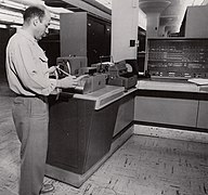
Tape reader used with a UNIVAC 1105 for the 1960 US Census
-
A large-capacity industrial tape reader
-
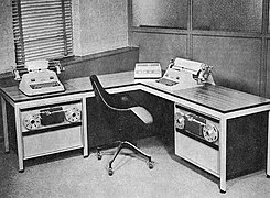
This early-1960s Monrobot XI computer used two paper tape reader/punches for offline data storage
-
Fanfold paper tape reader on a PDP-1 minicomputer (1960s)
-
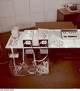
Paper tape readers for a word-processing system, c. 1970
-
Large IBM 1130 systems still handled paper tape in the early 1970s (at left of console)
-
Eight-hole tape from 1974
-
This 1970s DEC high-speed fanfold reader/punch used optical sensing
-
Paper tape loop controlling paper positioning in a IBM 1403 line printer (1959-1983)
-
Late-1970s heavy-duty tape punch used by the US National Security Agency for secret code distribution
-
Punch tape as an element of facade mosaic, Novosibirsk
See also
[edit]References
[edit]- ^ Maxfield, Clive (2011-10-13). "How it was: Paper tapes and punched cards". EE Times.
- ^ Roberts, Steven. "3. Cooke and Wheatstone". Distant Writing: A History of the Telegraph Companies in Britain between 1838 and 1868.
- ^ Smid, Peter (2010). CNC Control Setup for Milling and Turning: Mastering CNC Control Systems. Industrial Press. p. 20. ISBN 978-0-8311-3350-4.
- ^ Dalakov, Georgi, History of computers: The MARK computers of Howard Aiken, retrieved 2011-01-12
- ^ da Cruz, Frank (April 2021). "SSEC Tape". Columbia University Computing History. Retrieved 2024-05-25.
- ^ "CSIRAC paper tape (replica)". Computer History Museum. 2010. Retrieved 2023-10-13.
- ^ "ECMA standard for Data Interchange on Punched Tape". European Computer Manufacturers Association. November 1965. ECMA-10. Archived from the original on 2011-09-27. Retrieved 2003-07-10.
- ^ Lancaster, Don (2010), TV Typewriter Cookbook (PDF), Synergetics SP Press, p. 211
- ^ Proesch, Roland (2009). Technical Handbook for Radio Monitoring HF: Edition 2009. Books on Demand. ISBN 978-3837045734.
- ^ Hult, Ture (1963), "Presentation of a new high speed paper tape reader", BIT Numerical Mathematics, 3 (2): 93–96, doi:10.1007/BF01935575, S2CID 61020497
- ^ "Translation File Formats" (PDF). Data I/O Corporation. Retrieved 2010-08-30.
- ^ a b "Appendix A: A Sample Program in PL/M: BNPF Object Tape". MCS-8 A Guide to PL/M programming (PDF). Rev 1 (printed September 1974 ed.). 1974-03-15 [September 1973]. p. 101. MCS180-0774-1K, MCS280-0974-1K. Archived (PDF) from the original on 2022-01-29. Retrieved 2022-05-18. (1+i+100+1+11+1 pages)
- ^ a b Feichtinger, Herwig (1987). "1.8.5. Lochstreifen-Datenformate" [1.8.5. Paper tape data formats]. Arbeitsbuch Mikrocomputer [Microcomputer work book] (in German) (2 ed.). Munich, Germany: Franzis-Verlag GmbH. pp. 240–243. ISBN 3-7723-8022-0. (NB. The book contains a description of the BNPF format.)
- ^ a b "Chapter 6. Microcomputer System Component Data Sheet - EPROMs and ROM: I. PROM and ROM Programming Instructions - B2. BPNF Paper Tape Format". MCS-80 User's Manual (With Introduction to MCS-85). Intel Corporation. October 1977 [1975]. pp. 6–76. 98-153D. Retrieved 2020-02-27. [1][2] (NB. This manual describes a "BPNF Paper Tape Format", a "Non-Intellec Hex Paper Tape Format" and a "PN Computer Punched Card Format".)
- ^ "A. Serial Data Transfer Formats: ASCII BPNF, BHLF & B10F Formats". XP640 EPROM Programmer - User Manual (PDF). GP Industrial Electronics. 1984. p. 43. Archived (PDF) from the original on 2023-10-22. Retrieved 2023-10-22. (47 pages)
- ^ "Tale of the Tape". National Security Agency Central Security Service. 2016-05-03. Archived from the original on 2021-09-23. Retrieved 2014-06-16.
- ^ Sinha, Naresh K. (1986-06-30). Microprocessor-Based Control Systems. Springer. p. 264. ISBN 978-90-277-2287-4.
External links
[edit]
- A song mentioning paper tape
- Various punched media
- Olympia Flexowriter
- Detailed description of two paper tape code systems, Baudot code and the system used by the ILLIAC computer
- Working paper tape punch/reader GNT 3601, Musée Bolo, YouTube


