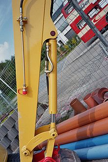
Slider crank chain inversion


Slider-crank chain inversion arises when the connecting rod, or coupler, of a slider-crank linkage becomes the ground link, so the slider is connected directly to the crank. This inverted slider-crank is the form of a slider-crank linkage that is often used to actuate a hinged joint in construction equipment like a crane or backhoe, as well as to open and close a swinging gate or door.[1][2][3]
Slider-crank and its inversions
A slider-crank is a four-bar linkage that has a crank that rotates coupled to a slider that moves along a straight line.
This mechanism is composed of three important parts: The crank which is the rotating disc, the slider which slides inside the tube and the connecting rod which joins the parts together. As the slider moves to the right the connecting rod pushes the wheel round for the first 180 degrees of wheel rotation. When the slider begins to move back into the tube, the connecting rod pulls the wheel round to complete the rotation.
Inversions
Different mechanism by fixing different link of slider crank chain are as follows :
- First inversion
This inversion is obtained when link 1 (ground body) is fixed. Application- Reciprocating engine, Reciprocating compressor etc...
- Second inversion
This inversion is obtained when link 2 (crank) is fixed. Application- Whitworth quick return mechanism, Rotary engine, etc...
- Third inversion
This inversion is obtained when link 3 (connecting rod) is fixed. Applications - Slotted crank mechanism, Oscillatory engine etc..,
- Fourth inversion
This inversion is obtained when link 4 (slider) is fixed. Application- Hand pump, pendulum pump or Bull engine, etc.
External links
- Inverted slider-crank linkage in the collection of Reuleaux models at Cornell University
- Mechanicaldesign101.com lecture notes on the slider-crank linkage.
References
- ^ Design of Machinery 3/e, Robert L. Norton, 2 May 2003, McGraw Hill. ISBN 0-07-247046-1
- ^ Myszka, David (2012). Machines and Mechanisms: Applied Kinematic Analysis. New Jersey: Pearson Education. ISBN 978-0-13-215780-3.
- ^ J. M. McCarthy and G. S. Soh, Geometric Design of Linkages, 2nd Edition, Springer 2010
