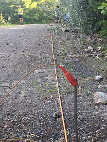
Electrical resistivity tomography
This article includes a list of general references, but it lacks sufficient corresponding inline citations. (December 2013) |


Electrical resistivity tomography (ERT) or electrical resistivity imaging (ERI) is a geophysical technique for imaging sub-surface structures from electrical resistivity measurements made at the surface, or by electrodes in one or more boreholes. If the electrodes are suspended in the boreholes, deeper sections can be investigated. It is closely related to the medical imaging technique electrical impedance tomography (EIT), and mathematically is the same inverse problem. In contrast to medical EIT, however, ERT is essentially a direct current method. A related geophysical method, induced polarization (or spectral induced polarization), measures the transient response and aims to determine the subsurface chargeability properties.
Electrical resistivity measurements can be used for identification and quantification of depth of groundwater, detection of clays, and measurement of groundwater conductivity.[1]
History
The technique evolved from techniques of electrical prospecting that predate digital computers, where layers or anomalies were sought rather than images. Early work on the mathematical problem in the 1930s assumed a layered medium (see for example Langer, Slichter). Andrey Nikolayevich Tikhonov who is best known for his work on regularization of inverse problems also worked on this problem. He explains in detail how to solve the ERT problem in a simple case of 2-layered medium. During the 1940s, he collaborated with geophysicists and without the aid of computers they discovered large deposits of copper. As a result, they were awarded a State Prize of Soviet Union.

When adequate computers became widely available, the inverse problem of ERT could be solved numerically. The work of Loke and Barker at Birmingham University was among the first such solution and their approach is still widely used.
With the advancement in the field of Electrical Resistivity Tomography (ERT) from 1D to 2D and nowadays 3D, ERT has explored many fields. The applications of ERT include fault investigation, ground water table investigation, soil moisture content determination and many others. In industrial process imaging ERT can be used in a similar fashion to medical EIT, to image the distribution of conductivity in mixing vessels and pipes. In this context it is usually called Electrical Resistance Tomography, emphasising the quantity that is measured rather than imaged.
Operating procedure
Soil resistivity, measured in ohm-centimeters (Ω⋅cm), varies with moisture content and temperature changes. In general, an increase in soil moisture results in a reduction in soil resistivity. The pore fluid provides the only electrical path in sands, while both the pore fluid and the surface charged particles provide electrical paths in clays. Resistivities of wet fine-grained soils are generally much lower than those of wet coarse-grained soils. The difference in resistivity between a soil in a dry and in a saturated condition may be several orders of magnitude.[2]
The method of measuring subsurface resistivity involves placing four electrodes in the ground in a line at equal spacing, applying a measured AC current to the outer two electrodes, and measuring the AC voltage between the inner two electrodes. A measured resistance is calculated by dividing the measured voltage by the measured current. This resistance is then multiplied by a geometric factor that includes the spacing between each electrode to determine the apparent resistivity.
Electrode spacings of 0.75, 1.5, 3.0, 6.0, and 12.0 m are typically used for shallow depths (<10 m) of investigations. Greater electrode spacings of 1.5, 3.0, 6.0, 15.0, 30.0, 100.0, and 150.0 m are typically used for deeper investigations. The depth of investigation is typically less than the maximum electrode spacing. Water is introduced to the electrode holes as the electrodes are driven into the ground to improve electrical contact.

See also
- Electrical capacitance tomography
- Electrical impedance tomography
- Magnetotellurics
- Seismo-electromagnetics
- Telluric current
- Vertical electrical sounding
- Geophysical Imaging
References
- Langer, R. E. (1933-10-01). "An inverse problem in differential equations". Bulletin of the American Mathematical Society. 39 (10). American Mathematical Society (AMS): 814–821. doi:10.1090/s0002-9904-1933-05752-x. ISSN 0002-9904.
- Slichter, L. B. (1933). "The Interpretation of the Resistivity Prospecting Method for Horizontal Structures". Physics. Vol. 4, no. 9. AIP Publishing. pp. 307–322. doi:10.1063/1.1745198. ISSN 0148-6349.
- Langer, R. E. (1936-10-01). "On the determination of earth conductivity from observed surface potentials". Bulletin of the American Mathematical Society. 42 (10). American Mathematical Society (AMS): 747–755. doi:10.1090/s0002-9904-1936-06420-7. ISSN 0002-9904.
- Tikhonov, A. N. (1949). О единственности решения задачи электроразведки. Doklady Akademii Nauk SSSR (in Russian). 69 (6): 797–800.
- A.P. Calderón, On an inverse boundary value problem, in Seminar on Numerical Analysis and its Applications to Continuum Physics, Rio de Janeiro. 1980. Scanned copy of paper
- Loke, M.H. (2004). Tutorial: 2-D and 3-D electrical imaging surveys (PDF). Retrieved 2007-06-11.
- Loke, M.H.; Barker, R.D. (1996). "Rapid least-squares inversion of apparent resistivity pseudosections by a quasi-Newton method". Geophysical Prospecting. 44 (1). Wiley: 131–152. doi:10.1111/j.1365-2478.1996.tb00142.x. ISSN 0016-8025.
- Loke, M.H.; Barker, R.D. (1996). "Practical techniques for 3D resistivity surveys and data inversion". Geophysical Prospecting. 44 (3). Wiley: 499–523. doi:10.1111/j.1365-2478.1996.tb00162.x. ISSN 0016-8025.
