
Environmental scanning electron microscope: Difference between revisions
→Gallery of ESEM images: image added |
mNo edit summary |
||
| Line 4: | Line 4: | ||
==History== |
==History== |
||
[[Image:ESEM_prototype.png|400 px|thumb|ESEM_prototype]] |
[[Image:ESEM_prototype.png|400 px|thumb|ESEM_prototype]] |
||
Since the early years of electron microscopy, many attempts have been reported on the examination of specimens inside “environmental” cells with water or atmospheric gas, in conjunction with conventional and scanning transmission type of [[electron microscope]]s<ref>Abrams I M and McBain J W (1944) A closed cell for electron microscopy, J. Appl. Physics, Vol. 15, 607-609</ref> <ref>Stoyanova I G (1961) Use of gas microcells in electron microscopy, Akademiya Nauk SSSR Isvestiya, ser. Fizicheskaya, Vol. 25, 715-721</ref> <ref>Swif J A and Brown A C (1970) An environmental cell for the examination of wet biological specimens at atmospheric pressure by transmission scanning electron microscopy, J. Phys. E, Vol 3, 924-926</ref> <ref>Parsons D F, Matricardi V R, Moretz R C and Turner J N (1974) Electron microscopy and diffraction of wet unstained and unfixed biological objects, Adv. Biol. Med. Phys., Vol. 15, 161-271</ref>. However, the first images of wet specimens in a SEM were reported by Lane in 1970<ref>Lane, W.C. (1970) The environmental control stage. Scanning Electron Microsc.: 43-48</ref>, who injected a very fine water vapor jet over the point of observation at the specimen surface; the gas diffused away into the vacuum of the specimen chamber without any modification to the instrument. In 1974, an improved approach was reported by Robinson<ref>Robinson, V.N.E. (1974) A wet stage modification to a scanning electron microscope. 8th Int. Congr. El. Microsc., Australian Academy of Science, Vol II:50-51</ref> with the use of a backscattered electron detector and differential pumping with a single aperture and the introduction of water vapor around 600 Pa pressure at the freezing point of temperature. However, neither of those approaches produced a stable enough instrument for routine operation. Starting work with Robinson in 1978 at the University of New South Wales in Sydney, Danilatos undertook a thorough quantitative study and experimentation that resulted in a stable operation of the microscope at room temperature and high pressures up to 7000 Pa, as reported in 1979<ref>Danilatos, G.D., and Robinson, V.N.E. (1979) Principles of scanning electron microscopy at high specimen pressures. Scanning 2:72-82</ref>. In the following years, Danilatos, working independently, reported a series of works on the design and construction of an environmental or atmospheric scanning electron microscope (ASEM) capable of working at any pressure from vacuum up to one atmosphere<ref>Danilatos, G.D. ( |
Since the early years of electron microscopy, many attempts have been reported on the examination of specimens inside “environmental” cells with water or atmospheric gas, in conjunction with conventional and scanning transmission type of [[electron microscope]]s<ref>Abrams I M and McBain J W (1944) A closed cell for electron microscopy, J. Appl. Physics, Vol. 15, 607-609</ref> <ref>Stoyanova I G (1961) Use of gas microcells in electron microscopy, Akademiya Nauk SSSR Isvestiya, ser. Fizicheskaya, Vol. 25, 715-721</ref> <ref>Swif J A and Brown A C (1970) An environmental cell for the examination of wet biological specimens at atmospheric pressure by transmission scanning electron microscopy, J. Phys. E, Vol 3, 924-926</ref> <ref>Parsons D F, Matricardi V R, Moretz R C and Turner J N (1974) Electron microscopy and diffraction of wet unstained and unfixed biological objects, Adv. Biol. Med. Phys., Vol. 15, 161-271</ref>. However, the first images of wet specimens in a SEM were reported by Lane in 1970<ref>Lane, W.C. (1970) The environmental control stage. Scanning Electron Microsc.: 43-48</ref>, who injected a very fine water vapor jet over the point of observation at the specimen surface; the gas diffused away into the vacuum of the specimen chamber without any modification to the instrument. In 1974, an improved approach was reported by Robinson<ref>Robinson, V.N.E. (1974) A wet stage modification to a scanning electron microscope. 8th Int. Congr. El. Microsc., Australian Academy of Science, Vol II:50-51</ref> with the use of a backscattered electron detector and differential pumping with a single aperture and the introduction of water vapor around 600 Pa pressure at the freezing point of temperature. However, neither of those approaches produced a stable enough instrument for routine operation. Starting work with Robinson in 1978 at the University of New South Wales in Sydney, Danilatos undertook a thorough quantitative study and experimentation that resulted in a stable operation of the microscope at room temperature and high pressures up to 7000 Pa, as reported in 1979<ref>Danilatos, G.D., and Robinson, V.N.E. (1979) Principles of scanning electron microscopy at high specimen pressures. Scanning 2:72-82</ref>. In the following years, Danilatos, working independently, reported a series of works on the design and construction of an environmental or atmospheric scanning electron microscope (ASEM) capable of working at any pressure from vacuum up to one atmosphere<ref>Danilatos, G.D. (1981) Design and construction of an atmospheric or environmental SEM (part 1). Scanning 4:9-20</ref> <ref>Danilatos, G.D., and Postle, R. (1983) Design and construction of an atmospheric or environmental SEM-2 . Micron 14:41-52</ref> <ref>Danilatos, G.D. (1985) Design and construction of an atmospheric or environmental SEM (part 3) . Scanning 7:26-42</ref> <ref>Danilatos, G.D. (1990) Design and construction of an environmental SEM (part 4). Scanning 12:23-27</ref>. These early works involved the optimization of the differential pumping system together with backscattered electron (BSE) detectors until 1983, when he invented the use of the environmental gas itself as a detection medium<ref>Danilatos, G.D. (1983) Gaseous detector device for an environmental electron probe microanalyzer . Research Disclosure No. 23311:284.</ref>. The decade of 1980 closed with the publication of two major works comprehensively dealing with the foundations of ESEM<ref>Danilatos, G.D. (1988) Foundations of Environmental Scanning Electron Microscopy . Advances in Electronics and Electron Physics, Academic Press, Vol. 71:109-250</ref> and the theory of the gaseous detection device (GDD)<ref>Danilatos, G.D. (1990) Theory of the Gaseous Detector Device in the ESEM . Advances in Electronics and Electron Physics, Academic Press, Vol. 78:1-102</ref>. Furthermore, in 1988, the first commercial ESEM was exhibited in New Orleans by ElectroScan Corporation, a venture capital company wishing to commercialize the Danilatos ESEM. The company placed an emphasis on the secondary electron (SE) mode of the GDD <ref>U.S. PATENT No. 4,785,182, filed May 21, 1987. Secondary electron detector for use in a gaseous atmosphere . Inventors: J.F. Mancuso, W.B. Maxwell, G.D. Danilatos. Assignee: ElectroScan Corporation</ref> and secured the monopoly of the commercial ESEM with a series of additional key patents<ref>U.S. Patent No. 4,596,928, filed May 14, 1984, (priority date July 3, 1979, Australia PD9433). Method and apparatus for an atmospheric scanning electron microscope . Inventor: G.D. Danilatos. Assignee: Unisearch Limited (Australia)</ref> <ref>U.S. PATENT No. 4,992,662, filed Sep. 13, 1989, (priority date Aug. 1, 1986, Australia, PH 07221). Multipurpose gaseous detector device for electron microscope . Inventor: G.D. Danilatos. Assignee: ElectroScan Corporation</ref> <ref>U.S. Patent No. 4,823,006, filed Feb. 19, 1988. Integrated electron optical/differential pumping/imaging signal detection system for an environmental scanning electron microscope . Inventors: G.D. Danilatos, G.C. Lewis. Assignee: ElectroScan Corporation</ref> <ref>U.S. PATENT No. 4,897,545, filed October 14, 1988 (priority date October 16, 1987, Australia PI4918). Electron detector for use in a gaseous environment by G.D. Danilatos</ref>. Philips and FEI companies succeeded ElectroScan in providing commercial ESEM instruments. With the expiration of key patents and assistance by Danilatos, new commercial instruments have been recently added to the market by LEO (succeeded by Carl Zeiss SMT). Further improvements have been reported to date from work on the original experimental prototype ESEM in Sydney and from numerous other workers using the commercial ESEM in a wide variety of applications worldwide. |
||
[[Image:ESEM_pumping.png|400 px|thumb|Basic ESEM gas pressure stages]] |
[[Image:ESEM_pumping.png|400 px|thumb|Basic ESEM gas pressure stages]] |
||
| Line 12: | Line 12: | ||
===Differential pumping=== |
===Differential pumping=== |
||
The specimen chamber sustaining the high pressure gaseous environment is separated from the high vacuum of the electron optics column with at least two small orifices customarily referred to as pressure limiting apertures (PLA). The gas leaking through the first aperture (PLA1) is quickly removed from the system with a pump that maintains a much lower pressure in the downstream region (i.e. immediately above the aperture). This is called differential pumping. Some gas escapes further from the low pressure region (stage 1) through a second pressure limiting aperture (PLA2) into the vacuum region of the column above, which constitutes a second stage differential pumping (stage 2). A schematic diagram shows the basic ESEM gas pressure stages including the specimen chamber, intermediate cavity and upper electron optics column. The corresponding pressures achieved are p<sub>0</sub>>>p<sub>1</sub>>>p<sub>2</sub>, which is a sufficient condition for a microscope employing a tungsten type of electron gun. Additional pumping stages may be added to achieve an even higher vacuum as required for a LaB<sub>6</sub> and field emission type electron guns. The design and shape of a pressure limiting aperture are critical in obtaining the sharpest possible pressure gradient (transition) through it. This is achieved with an orifice made on a thin plate and tapered in the downstream direction as shown in the accompanying isodensity contours of a gas flowing through the PLA1. This was done with a computer simulation of the gas molecule collisions and movement through space in real time<ref>Danilatos GD ( |
The specimen chamber sustaining the high pressure gaseous environment is separated from the high vacuum of the electron optics column with at least two small orifices customarily referred to as pressure limiting apertures (PLA). The gas leaking through the first aperture (PLA1) is quickly removed from the system with a pump that maintains a much lower pressure in the downstream region (i.e. immediately above the aperture). This is called differential pumping. Some gas escapes further from the low pressure region (stage 1) through a second pressure limiting aperture (PLA2) into the vacuum region of the column above, which constitutes a second stage differential pumping (stage 2). A schematic diagram shows the basic ESEM gas pressure stages including the specimen chamber, intermediate cavity and upper electron optics column. The corresponding pressures achieved are p<sub>0</sub>>>p<sub>1</sub>>>p<sub>2</sub>, which is a sufficient condition for a microscope employing a tungsten type of electron gun. Additional pumping stages may be added to achieve an even higher vacuum as required for a LaB<sub>6</sub> and field emission type electron guns. The design and shape of a pressure limiting aperture are critical in obtaining the sharpest possible pressure gradient (transition) through it. This is achieved with an orifice made on a thin plate and tapered in the downstream direction as shown in the accompanying isodensity contours of a gas flowing through the PLA1. This was done with a computer simulation of the gas molecule collisions and movement through space in real time<ref>Danilatos GD (2000) Direct simulation Monte Carlo study of orifice flow. Rarefied Gas Dynamics: 22nd Intern. Symp., Sydney, (Eds. TJ Bartel and MA Gallis), Am. Inst. Phys., AIP Conference Proceedings, Vol. 585, pp. 924-932.</ref>. We can immediately see that the gas density decreases by about two orders of magnitude over the length of a few aperture radii. This is a quantitatively vivid demonstration of a first principle that enables the separation of the high pressure specimen chamber from the low pressure and vacuum regions above. |
||
By such means, the gas flow fields have been studied in a variety of instrument situations<ref>Danilatos GD (2001) Electron beam loss at the high-vacuum-high-pressure boundary in the environmental scanning electron microscope. Microsc. and Microanal. 7, 397-406</ref>, in which subsequently the electron beam transfer has been quantified. |
By such means, the gas flow fields have been studied in a variety of instrument situations<ref>Danilatos GD (2001) Electron beam loss at the high-vacuum-high-pressure boundary in the environmental scanning electron microscope. Microsc. and Microanal. 7, 397-406</ref>, in which subsequently the electron beam transfer has been quantified. |
||
| Line 35: | Line 35: | ||
====Backscattered electrons==== |
====Backscattered electrons==== |
||
[[Image:ESEM_BSE.png|400 px|thumb|Optimum BSE detectors in ESEM]]The backscattered electrons are conventionally associated with those electrons emanating from the beam-specimen interaction by having energies greater than 50 eV up to the primary beam energy for reflected electrons. These electrons also operate in the gaseous volume between the electrodes of the GDD, and thus generate additional ionization and avalanche amplification. However, the corresponding component is small compared to the total secondary electron signal, provided the detection volume for the secondary electrons is separated out from the remaining outer region which constitutes a detection volume for the backscattered electrons. The relationship of relative strength of the two signals, SE and BSE, has been worked out by detailed equations of charge distribution in the ESEM<ref>Danilatos, G.D. ( |
[[Image:ESEM_BSE.png|400 px|thumb|Optimum BSE detectors in ESEM]]The backscattered electrons are conventionally associated with those electrons emanating from the beam-specimen interaction by having energies greater than 50 eV up to the primary beam energy for reflected electrons. These electrons also operate in the gaseous volume between the electrodes of the GDD, and thus generate additional ionization and avalanche amplification. However, the corresponding component is small compared to the total secondary electron signal, provided the detection volume for the secondary electrons is separated out from the remaining outer region which constitutes a detection volume for the backscattered electrons. The relationship of relative strength of the two signals, SE and BSE, has been worked out by detailed equations of charge distribution in the ESEM<ref>Danilatos, G.D. (1990) Equations of charge distribution in the ESEM . Scanning Microscopy, Vol 4, No. 4:799-823</ref>. The analysis of plane electrodes is essential in understanding the principles and requirements involved and by no means indicate the best choice of electrode configuration, as discussed in the published theory of the GDD. |
||
Despite the above developments, devoted BSE detectors in the ESEM have played an important role, since the BSE remain a most useful detection mode yielding information not possible to obtain with SE. The conventional BSE detection means have been adapted to operate in the gaseous conditions of the ESEM. The BSE having a high energy are self-propelled to the corresponding detector without significant obstruction by the gas molecules. Already, annular or quadrant solid state detectors have been employed for this purpose but their geometry is not easily adapted to the requirement of ESEM for optimum operation. As a result, no much use has been reported of these detectors on genuine ESEM instruments. However, plastic scintillating materials have been used for BSE and made to measure according to the strictest requirement of the system. This work culminated with use of a pair of wedge-shaped detectors saddling a conical PLA1 and abutting to its rim, so that the dead detection space is reduced to a minimum, as shown in the accompanying figure of optimum BSE detectors (Danilatos, 1985). The photon conduction is also optimized by the geometry of the light pipes, whilst the pair of symmetrical detectors allow the separation of topography (signal subtraction) and atomic number contrast (signal addition) of the specimen surface to be displayed with the best ever signal-to-noise-ratio. This scheme has further allowed the use of color by superimposing various signals in a meaningful way<ref>Danilatos, G.D. ( |
Despite the above developments, devoted BSE detectors in the ESEM have played an important role, since the BSE remain a most useful detection mode yielding information not possible to obtain with SE. The conventional BSE detection means have been adapted to operate in the gaseous conditions of the ESEM. The BSE having a high energy are self-propelled to the corresponding detector without significant obstruction by the gas molecules. Already, annular or quadrant solid state detectors have been employed for this purpose but their geometry is not easily adapted to the requirement of ESEM for optimum operation. As a result, no much use has been reported of these detectors on genuine ESEM instruments. However, plastic scintillating materials have been used for BSE and made to measure according to the strictest requirement of the system. This work culminated with use of a pair of wedge-shaped detectors saddling a conical PLA1 and abutting to its rim, so that the dead detection space is reduced to a minimum, as shown in the accompanying figure of optimum BSE detectors (Danilatos, 1985). The photon conduction is also optimized by the geometry of the light pipes, whilst the pair of symmetrical detectors allow the separation of topography (signal subtraction) and atomic number contrast (signal addition) of the specimen surface to be displayed with the best ever signal-to-noise-ratio. This scheme has further allowed the use of color by superimposing various signals in a meaningful way<ref>Danilatos, G.D. (1986) Colour micrographs for backscattered electron signals in the SEM . Scanning 8:9-18</ref>. These plain detectors became possible in the conditions of ESEM, since bare plastic does not charge by the BSE. However, a very fine wire mesh with appropriate spacing has been proposed (<ref>Danilatos, G.D. (1993) Universal ESEM. Proc. 51st Annual Meeting MSA, (Eds. GW Bailey and LC Rieder), San Francisco Press, San Francisco:786-787</ref>) as a GDD when gas is present and to conduct negative charge away from the plastic detectors when the gas is pumped out, towards a universal ESEM. |
||
The use of such detectors in ESEM is compatible with the GDD for simultaneous SE detection, in one way by replacing the top plane electrode with a fine tip needle electrode (detector), which can be easily accommodated with these scintillating BSE detectors. The needle detector and cylindrical geometry (wire) have also been extensively surveyed in the quoted “Theory” of the GDD. |
The use of such detectors in ESEM is compatible with the GDD for simultaneous SE detection, in one way by replacing the top plane electrode with a fine tip needle electrode (detector), which can be easily accommodated with these scintillating BSE detectors. The needle detector and cylindrical geometry (wire) have also been extensively surveyed in the quoted “Theory” of the GDD. |
||
====Cathodoluminescence==== |
====Cathodoluminescence==== |
||
Cathodoluminscence is another mode of detection involving the photons generated by the beam-specimen interaction. This mode has been demonstrated to operate also in ESEM by the use of the light pipes after they were cleared of the scintillating coating previously used for BSE detection. However, not much is known on its use outside the experimental prototype originally tested<ref>Danilatos, G.D. ( |
Cathodoluminscence is another mode of detection involving the photons generated by the beam-specimen interaction. This mode has been demonstrated to operate also in ESEM by the use of the light pipes after they were cleared of the scintillating coating previously used for BSE detection. However, not much is known on its use outside the experimental prototype originally tested<ref>Danilatos, G.D. (1986) Cathodoluminescence and gaseous scintillation in the environmental SEM . Scanning 8:279-284</ref>. Clearly, ESEM is more powerful and meaningful under this detection mode than SEM, since the natural surface of any specimen can be examined in the imaging process. Cathodoluminescence is a materials property, but with various specimen treatments required and other limitations in SEM the properties are obscured or altered or impossible to detect and hence this mode of detection has not become popular in the past. The advent of ESEM with its unlimited potential may provoke more interest in this area too, in the future. |
||
====X-rays==== |
====X-rays==== |
||
The characteristic elemental x-rays produced also in the ESEM can be detected by the same detectors used in the SEM. However, there is an additional complexity arising from the x-rays produced from the electron skirt. These x-rays come from a larger area than in SEM and the spatial resolution is significantly reduced, since the “background” x-ray signals cannot be simply “suppressed” out of the probe interaction volume. However, various schemes have been proposed to solve this problem<ref>Bolon, R.B., Roberstson, C.D. (1990) X-ray and microstructural ESEM analysis of non conducting materials in gaseous environments. Scanning 90 Abstracts, FACMS Inc.:80-81.</ref> <ref>Bolon, R.B. ( |
The characteristic elemental x-rays produced also in the ESEM can be detected by the same detectors used in the SEM. However, there is an additional complexity arising from the x-rays produced from the electron skirt. These x-rays come from a larger area than in SEM and the spatial resolution is significantly reduced, since the “background” x-ray signals cannot be simply “suppressed” out of the probe interaction volume. However, various schemes have been proposed to solve this problem<ref>Bolon, R.B., Roberstson, C.D. (1990) X-ray and microstructural ESEM analysis of non conducting materials in gaseous environments. Scanning 90 Abstracts, FACMS Inc.:80-81.</ref> <ref>Bolon, R.B. (1991) ESEM, the technique and application to materials characterization. Proc. Scanning '91, Scanning 13, Suppl. I:86-87</ref> <ref>Bolon, R.B. (1991) X-ray microanalysis in the ESEM. Microbeam Analysis-1991, (Ed. D.G. Howitt) San Francisco Press, San Francisco:199-200</ref> <ref>Danilatos, G.D. (1994) Environmental scanning electron microscopy and microanalysis , Mikrochimica Acta 114/115:143-155</ref>. These methods involve spot masking, or the extrapolation technique by varying the pressure and calibrating out the effects of skirt, whereby considerable improvement has been achieved. |
||
===Specimen charging=== |
===Specimen charging=== |
||
The electron beam impinging on insulating specimens accumulates negative charge, which creates an electrical potential tending to deflect the electron beam from the scanned point in conventional SEM. This appears as charging artifacts on the image, which are eliminated in the SEM by depositing a conductive layer on the specimen surface prior to examination. In lieu of this coating, the gas in the ESEM being electrically conductive prevents negative charge accumulation. The good conductivity of the gas is due to the ionization it undergoes by the incident electron beam and the ionizing SE and BSE signals<ref>Moncrieff, D.A., Robinson, V.N.E., and Harris, L.B. (1978) Charge neutralisation of |
The electron beam impinging on insulating specimens accumulates negative charge, which creates an electrical potential tending to deflect the electron beam from the scanned point in conventional SEM. This appears as charging artifacts on the image, which are eliminated in the SEM by depositing a conductive layer on the specimen surface prior to examination. In lieu of this coating, the gas in the ESEM being electrically conductive prevents negative charge accumulation. The good conductivity of the gas is due to the ionization it undergoes by the incident electron beam and the ionizing SE and BSE signals<ref>Moncrieff, D.A., Robinson, V.N.E., and Harris, L.B. (1978) Charge neutralisation of |
||
insulating surfaces in the SEM by gas ionisation. J. Phys. D: Appl. Phys. 11:2315-2325.</ref> <ref>Danilatos, G.D. ( |
insulating surfaces in the SEM by gas ionisation. J. Phys. D: Appl. Phys. 11:2315-2325.</ref> <ref>Danilatos, G.D. (1993) Environmental scanning electron microscope-some critical issues . Scanning Microscopy International, Supplement 7, 1993:57-80</ref>. This principle, constitutes yet another fundamental deviation from conventional vacuum electron microscopy, with enormous advantages. |
||
===Contrast and resolution=== |
===Contrast and resolution=== |
||
| Line 65: | Line 65: | ||
==Applications== |
==Applications== |
||
The first application of ESEM involved the examination of fresh and living plant material, specifically on a study of Leptospermum ''flavescens''<ref>Danilatos, G.D. ( |
The first application of ESEM involved the examination of fresh and living plant material, specifically on a study of Leptospermum ''flavescens''<ref>Danilatos, G.D. (1981) The examination of fresh or living plant material in an environmental scanning electron microscope. J. Microsc. 121:235-238</ref>. A second application was done in wool research by imaging fibers with and without particular chemical and mechanical treatments as they apply to the wool industry<ref>Danilatos, G.D., and Brooks, J.H. (1985) Environmental SEM in wool research - present state of the art . Proc. 7th Int. Wool Textile Research Conference, Tokyo, I:263-272</ref>. Further, a very large number of applications has been reported with the use of commercial ESEM worldwide and a representative selection is presented below. (to be done by new contributors) |
||
Revision as of 12:07, 11 May 2008
ESEM stands for environmental scanning electron microscope. This is a scanning electron microscope (SEM) that allows a gaseous environment in the specimen chamber. Whereas all conventional microscopes operate in vacuum, the ESEM has added a new dimension to electron microscopy with enormous advantages.
History
Since the early years of electron microscopy, many attempts have been reported on the examination of specimens inside “environmental” cells with water or atmospheric gas, in conjunction with conventional and scanning transmission type of electron microscopes[1] [2] [3] [4]. However, the first images of wet specimens in a SEM were reported by Lane in 1970[5], who injected a very fine water vapor jet over the point of observation at the specimen surface; the gas diffused away into the vacuum of the specimen chamber without any modification to the instrument. In 1974, an improved approach was reported by Robinson[6] with the use of a backscattered electron detector and differential pumping with a single aperture and the introduction of water vapor around 600 Pa pressure at the freezing point of temperature. However, neither of those approaches produced a stable enough instrument for routine operation. Starting work with Robinson in 1978 at the University of New South Wales in Sydney, Danilatos undertook a thorough quantitative study and experimentation that resulted in a stable operation of the microscope at room temperature and high pressures up to 7000 Pa, as reported in 1979[7]. In the following years, Danilatos, working independently, reported a series of works on the design and construction of an environmental or atmospheric scanning electron microscope (ASEM) capable of working at any pressure from vacuum up to one atmosphere[8] [9] [10] [11]. These early works involved the optimization of the differential pumping system together with backscattered electron (BSE) detectors until 1983, when he invented the use of the environmental gas itself as a detection medium[12]. The decade of 1980 closed with the publication of two major works comprehensively dealing with the foundations of ESEM[13] and the theory of the gaseous detection device (GDD)[14]. Furthermore, in 1988, the first commercial ESEM was exhibited in New Orleans by ElectroScan Corporation, a venture capital company wishing to commercialize the Danilatos ESEM. The company placed an emphasis on the secondary electron (SE) mode of the GDD [15] and secured the monopoly of the commercial ESEM with a series of additional key patents[16] [17] [18] [19]. Philips and FEI companies succeeded ElectroScan in providing commercial ESEM instruments. With the expiration of key patents and assistance by Danilatos, new commercial instruments have been recently added to the market by LEO (succeeded by Carl Zeiss SMT). Further improvements have been reported to date from work on the original experimental prototype ESEM in Sydney and from numerous other workers using the commercial ESEM in a wide variety of applications worldwide.

How it works
Basically, an ESEM employs a scanned electron beam and electromagnetic lenses to focus and direct the beam on the specimen surface in an identical way as a conventional SEM. A very small focussed electron spot (probe) is scanned in a raster form over a small specimen area. The beam electrons interact with the specimen surface layer and produce various signals (information) that are collected with appropriate detectors. The output of these detectors modulates, via appropriate electronics, the screen of a monitor to form an image that corresponds to the small raster and information, pixel by pixel, emanating from the specimen surface. Beyond these common principles, the ESEM deviates substantially from a SEM in several respects, all of which are important in the correct design and operation of the instrument. The outline below highlights these requirements and how the system works.
Differential pumping
The specimen chamber sustaining the high pressure gaseous environment is separated from the high vacuum of the electron optics column with at least two small orifices customarily referred to as pressure limiting apertures (PLA). The gas leaking through the first aperture (PLA1) is quickly removed from the system with a pump that maintains a much lower pressure in the downstream region (i.e. immediately above the aperture). This is called differential pumping. Some gas escapes further from the low pressure region (stage 1) through a second pressure limiting aperture (PLA2) into the vacuum region of the column above, which constitutes a second stage differential pumping (stage 2). A schematic diagram shows the basic ESEM gas pressure stages including the specimen chamber, intermediate cavity and upper electron optics column. The corresponding pressures achieved are p0>>p1>>p2, which is a sufficient condition for a microscope employing a tungsten type of electron gun. Additional pumping stages may be added to achieve an even higher vacuum as required for a LaB6 and field emission type electron guns. The design and shape of a pressure limiting aperture are critical in obtaining the sharpest possible pressure gradient (transition) through it. This is achieved with an orifice made on a thin plate and tapered in the downstream direction as shown in the accompanying isodensity contours of a gas flowing through the PLA1. This was done with a computer simulation of the gas molecule collisions and movement through space in real time[20]. We can immediately see that the gas density decreases by about two orders of magnitude over the length of a few aperture radii. This is a quantitatively vivid demonstration of a first principle that enables the separation of the high pressure specimen chamber from the low pressure and vacuum regions above.
By such means, the gas flow fields have been studied in a variety of instrument situations[21], in which subsequently the electron beam transfer has been quantified.

Electron beam transfer
By the use of differential pumping, an electron beam is generated and propagated freely in the vacuum of the upper column, from the electron gun down to PLA2, from which point onwards the electron beam gradually loses electrons due to electron scattering by gas molecules. Initially, the amount of electron scattering is negligible inside the intermediate cavity, but as the beam encounters an increasingly denser gas jet formed by the PLA1, the losses become significant. After the beam enters the specimen chamber, the electron losses increase exponentially at a rate depending on the prevailing pressure, the nature of gas and the accelerating voltage of the beam. Eventually, the electron beam becomes totally scattered and lost, but before this happens, a useful amount of electrons is retained in the original focussed spot over a finite distance, which can still be used for imaging. This is possible because the removed electrons are scattered and distributed over a broad area like a skirt surrounding the focussed spot. Because the electron skirt width is orders of magnitude greater than the spot width, with orders of magnitude less current density, the skirt contributes only background (signal) noise without partaking in the contrast generated by the central spot.
For a given beam accelerating voltage and gas, the distance L from PLA1, over which useful imaging is possible, is inversely proportional to the chamber pressure p0. As a rule of thumb, for a 5 kV beam in air, it is required that the product p0L=1 Pa-m or less. By this second principle of electron beam transfer, the design and operation of an ESEM is centered around refining and miniaturizing all the devices controlling the specimen movement and manipulation, and signal detection. The problem then reduces to achieving sufficient engineering precision for the instrument to operate close to its physical limit, corresponding to optimum performance and range of capabilities.
Signal detection
The electron beam impinges on the specimen and penetrates to a certain depth depending on the accelerating voltage and the specimen nature. From the ensuing interaction, signals are generated in the same way as in a SEM. Thus, we get secondary and backscattered electrons, x-rays and cathodoluminescence (light). All of these signals are detected also in the ESEM but with certain differences in the detector design and principles used.


Secondary electrons
The conventional secondary electron detector of SEM cannot be used in the presence of gas because of an electrical discharge (arcing) caused by the kilovolt bias associated with this detector. In lieu of this, an electrode is used biased with several hundred volts or less to collect the secondary electrons in the ESEM. The principle of this detector is best described by considering two parallel plates at a distance d apart with a potential difference V generating a uniform electric field E=V/d as shown in the accompanying diagram of the gaseous detection device (GDD). This configuration is taken from the theory of the detector and a book chapter on ESEM[22]. Secondary electrons released from the specimen at the point of beam impingement are driven by the field force towards the anode electrode but the electrons also move radially due to thermal diffusion from collisions with the gas molecules. The variation of electron collection fraction within anode radius r vs. r/d, for fixed values of anode bias (V), at constant product of (pressurexdistance) pd=1 Pa-m, is is given by the accompanying characteristic curves of efficiency of the GDD. We see that all of the secondary electrons are detected if the parameters of this device are properly designed. This clearly shows that practically 100% efficiency is possible within a small radius of collector electrode with only moderate bias. At these levels of bias, no catastrophic discharge takes place. Instead, a controlled proportional multiplication of electrons is generated as the electrons collide with gas molecules releasing new electrons on their way to the anode. This principle of avalanche amplification operates similarly to proportional amplifiers used in nuclear physics detectors. The signal thus picked up by the anode is further amplified and processed to modulate a display screen and form an image as in SEM. Notably, in this design and the associated amplification gain, the product pd is an independent parameter, so that there is a wide range of values of pressure and electrode geometry which can be described by the same characteristics. The consequence of this analysis is that the secondary electrons are possible to detect in a gaseous environment even at high pressures, depending on the engineering efficacy of any given instrument.
As a further characteristic of the GDD, a gaseous avalanche scintillation also accompanies the electron avalanche and, by detection of the light produced with a photo-multiplier, corresponding SE images can be routinely made. This characteristic of the detector has been employed by a latest generation of commercial instruments. As is further explained below, backscattered electrons can also be detected by the signal-gas interactions so that the GDD constitutes a generalized detector. Various parameters of this detector control or separate the various signals detected. In this connection, some workers and manufacturers have taken care to produce more or less "pure" SE images with their detectors, to which they have referred as ESD (environmental secondary detector) or GSED (gaseous secondary electron detector).
The novel GDD has become possible only in the ESEM and has produced an ideal 100% SE collection efficiency not previously possible with the Everhadt-Thornley detector where the free trajectories of electrons in vacuum cannot all be bent towards the detector.
Backscattered electrons

The backscattered electrons are conventionally associated with those electrons emanating from the beam-specimen interaction by having energies greater than 50 eV up to the primary beam energy for reflected electrons. These electrons also operate in the gaseous volume between the electrodes of the GDD, and thus generate additional ionization and avalanche amplification. However, the corresponding component is small compared to the total secondary electron signal, provided the detection volume for the secondary electrons is separated out from the remaining outer region which constitutes a detection volume for the backscattered electrons. The relationship of relative strength of the two signals, SE and BSE, has been worked out by detailed equations of charge distribution in the ESEM[23]. The analysis of plane electrodes is essential in understanding the principles and requirements involved and by no means indicate the best choice of electrode configuration, as discussed in the published theory of the GDD.
Despite the above developments, devoted BSE detectors in the ESEM have played an important role, since the BSE remain a most useful detection mode yielding information not possible to obtain with SE. The conventional BSE detection means have been adapted to operate in the gaseous conditions of the ESEM. The BSE having a high energy are self-propelled to the corresponding detector without significant obstruction by the gas molecules. Already, annular or quadrant solid state detectors have been employed for this purpose but their geometry is not easily adapted to the requirement of ESEM for optimum operation. As a result, no much use has been reported of these detectors on genuine ESEM instruments. However, plastic scintillating materials have been used for BSE and made to measure according to the strictest requirement of the system. This work culminated with use of a pair of wedge-shaped detectors saddling a conical PLA1 and abutting to its rim, so that the dead detection space is reduced to a minimum, as shown in the accompanying figure of optimum BSE detectors (Danilatos, 1985). The photon conduction is also optimized by the geometry of the light pipes, whilst the pair of symmetrical detectors allow the separation of topography (signal subtraction) and atomic number contrast (signal addition) of the specimen surface to be displayed with the best ever signal-to-noise-ratio. This scheme has further allowed the use of color by superimposing various signals in a meaningful way[24]. These plain detectors became possible in the conditions of ESEM, since bare plastic does not charge by the BSE. However, a very fine wire mesh with appropriate spacing has been proposed ([25]) as a GDD when gas is present and to conduct negative charge away from the plastic detectors when the gas is pumped out, towards a universal ESEM.
The use of such detectors in ESEM is compatible with the GDD for simultaneous SE detection, in one way by replacing the top plane electrode with a fine tip needle electrode (detector), which can be easily accommodated with these scintillating BSE detectors. The needle detector and cylindrical geometry (wire) have also been extensively surveyed in the quoted “Theory” of the GDD.
Cathodoluminescence
Cathodoluminscence is another mode of detection involving the photons generated by the beam-specimen interaction. This mode has been demonstrated to operate also in ESEM by the use of the light pipes after they were cleared of the scintillating coating previously used for BSE detection. However, not much is known on its use outside the experimental prototype originally tested[26]. Clearly, ESEM is more powerful and meaningful under this detection mode than SEM, since the natural surface of any specimen can be examined in the imaging process. Cathodoluminescence is a materials property, but with various specimen treatments required and other limitations in SEM the properties are obscured or altered or impossible to detect and hence this mode of detection has not become popular in the past. The advent of ESEM with its unlimited potential may provoke more interest in this area too, in the future.
X-rays
The characteristic elemental x-rays produced also in the ESEM can be detected by the same detectors used in the SEM. However, there is an additional complexity arising from the x-rays produced from the electron skirt. These x-rays come from a larger area than in SEM and the spatial resolution is significantly reduced, since the “background” x-ray signals cannot be simply “suppressed” out of the probe interaction volume. However, various schemes have been proposed to solve this problem[27] [28] [29] [30]. These methods involve spot masking, or the extrapolation technique by varying the pressure and calibrating out the effects of skirt, whereby considerable improvement has been achieved.
Specimen charging
The electron beam impinging on insulating specimens accumulates negative charge, which creates an electrical potential tending to deflect the electron beam from the scanned point in conventional SEM. This appears as charging artifacts on the image, which are eliminated in the SEM by depositing a conductive layer on the specimen surface prior to examination. In lieu of this coating, the gas in the ESEM being electrically conductive prevents negative charge accumulation. The good conductivity of the gas is due to the ionization it undergoes by the incident electron beam and the ionizing SE and BSE signals[31] [32]. This principle, constitutes yet another fundamental deviation from conventional vacuum electron microscopy, with enormous advantages.
Contrast and resolution
As a consequence of the way ESEM works, the resolution is preserved relative to the SEM. That is because the resolving power of the instrument is determined by the electron beam diameter which is unaffected by the gas over the useful travel distance before it is completely lost. This has been demonstrated on the commercial ESEMs that provide the finest beam spots by imaging test specimens, i.e. customarily gold particles on a carbon substrate, in both vacuum and gas. However, the contrast decreases accordingly as the electron probe loses current with travel distance and increase of pressure. The loss of current intensity, if necessary, can be compensated by increasing the incident beam current which is accompanied by a increased spot size. Therefore, the practical resolution depends on the original specimen contrast of a given feature, on the design of the instrument that should provide minimal beam and signal losses and on the operator selecting the correct parameters for each application. The aspects of contrast and resolution have been conclusively determined in the referenced work on the foundations of ESEM. Further, in relation to this, we have to consider the radiation effects on the specimen.
Specimen transfer
The majority of available instruments vent their specimen chamber to the ambient pressure (100 kPa) with every specimen transfer. A large volume of gas has to be pumped out and replaced with the gas of interest, usually water vapor supplied from a water reservoir connected to the chamber via some pressure regulating (e.g. needle) valve. In many applications this presents no problem, but with those ones requiring uninterrupted 100% relative humidity, it has been found that the removal of ambient gas is accompanied by lowering the relative humidity below the 100% level during specimen transfer. This clearly defeats the very purpose of ESEM for this class of applications. However, such a problem does not arise with the original prototype ESEM using an intermediate specimen transfer chamber, so that the main chamber is always maintained at 100% relative humidity without interruption during a study. The specimen transfer chamber (tr-ch) shown in the diagram of ESEM gas pressure stages contains a small water reservoir so that the initial ambient air can be quickly pumped out and practically instantaneously replaced with water vapor without going through a limited conductance tube and valve. The main specimen chamber can be maintained at 100% relative humidity, if the only leak of vapor is through the small PLA1, but not during violent pumping with every specimen change. Once the wet specimen is in equilibrium with 100% relative humidity in the transfer chamber, within seconds, a gate valve opens and the specimen is transferred in the main specimen chamber maintained at the same pressure. An alternative approach involving controlled pumping of the main chamber[33] may not solve the problem entirely either because the 100% relative humidity cannot be approached monotonically without any drying, or the process is very slow; inclusion of a water reservoir inside the main chamber means that one cannot lower the relative humidity until after all of the water is pumped out (i.e. a defective control of the relative humidity).
Radiation effects
Advantages
The presence of gas around a specimen creates new possibilities unique to ESEM: (a) Hydrated specimens can be examined since any pressure greater than 609 Pa allows water to be maintained in its liquid phase for temperatures above 0 degrees Celsius, in contrast to the SEM where specimens are desiccated by the vacuum condition. (b) Electrically non-conductive specimens do not require the preparation techniques used in SEM to render the surface conductive, such as the deposition of a thin gold or carbon coating, or other treatments, techniques which also require vacuum in the process. Insulating specimens charge up by the electron beam making imaging problematic or even impossible. (c) The gas itself is used as a detection medium producing novel imaging possibilities, as opposed to vacuum SEM detectors. (d) Plain plastic scintillating BSE detectors can operate uncoated without charging. Hence, these detectors produce the highest possible signal-to-noise-ratio at the lowest possible accelerating voltage, because the BSE do not dissipate any energy in an aluminum coating used for the vacuum SEM.
As a result, specimens can be examined faster and easier avoiding complex and time consuming preparation methods, without modifying the natural surface or creating artifacts by the preceding preparation work, or the vacuum of the SEM. Gas/liquid/solid interactions can be studied dynamically in situ and in real time, or recorded for post processing. Temperature variations from subzero to above 1000 degrees Celsius and various ancillary devices for specimen micro-manipulation have become a new reality. Biological specimens can be maintained fresh and live. Therefore, ESEM constitutes a radical breakthrough from conventional electron microscopy, where the vacuum condition precluded the advantages of electron beam imaging becoming universal.
Applications
The first application of ESEM involved the examination of fresh and living plant material, specifically on a study of Leptospermum flavescens[34]. A second application was done in wool research by imaging fibers with and without particular chemical and mechanical treatments as they apply to the wool industry[35]. Further, a very large number of applications has been reported with the use of commercial ESEM worldwide and a representative selection is presented below. (to be done by new contributors)
Commercial ESEM
The ESEM has appeared under different manufacturing brand names. The term ESEM is a generic name first publicly introduced in 1980[36]. It seems then inappropriate that ElectroScan obtained a trade mark on ESEM name, intermittently, until 1999, when it was allowed to lapse. The word “environmental” was originally introduced in continuation to the prior (historical) use of “environmental” cells in transmission microscopy, although the word “atmospheric” has also been used to refer to an ESEM at one atmosphere pressure (ASEM) but not with any commercial instruments. Other competing manufacturers have used the terms “Natural SEM”, “Wet-SEM”, “Bio-SEM”, “VP-SEM” (variable pressure-SEM), “LVSEM” (low-vacuum SEM, often also denoting low-voltage SEM). Until recently, all these names referred to instruments operating up to about 100 Pa and with BSE detectors only. Lately, the VP-SEM has been extended to higher pressure together with a needle gaseous detector and gaseous scintillation as the SE mechanism for image formation. Therefore, it is improper to identify the term ESEM with one only brand of commercial instrument in juxtaposition to other competing commercial brands with different names, as some confusion may arise from past improper use of the term ESEM as a trademark.
Similarly, the term GDD is generic covering the entire novel gaseous detection principle in ESEM, but some users and the manufacturer have used the terms ESD and GSED to denote the secondary electron mode of this detector.
References
- ^ Abrams I M and McBain J W (1944) A closed cell for electron microscopy, J. Appl. Physics, Vol. 15, 607-609
- ^ Stoyanova I G (1961) Use of gas microcells in electron microscopy, Akademiya Nauk SSSR Isvestiya, ser. Fizicheskaya, Vol. 25, 715-721
- ^ Swif J A and Brown A C (1970) An environmental cell for the examination of wet biological specimens at atmospheric pressure by transmission scanning electron microscopy, J. Phys. E, Vol 3, 924-926
- ^ Parsons D F, Matricardi V R, Moretz R C and Turner J N (1974) Electron microscopy and diffraction of wet unstained and unfixed biological objects, Adv. Biol. Med. Phys., Vol. 15, 161-271
- ^ Lane, W.C. (1970) The environmental control stage. Scanning Electron Microsc.: 43-48
- ^ Robinson, V.N.E. (1974) A wet stage modification to a scanning electron microscope. 8th Int. Congr. El. Microsc., Australian Academy of Science, Vol II:50-51
- ^ Danilatos, G.D., and Robinson, V.N.E. (1979) Principles of scanning electron microscopy at high specimen pressures. Scanning 2:72-82
- ^ Danilatos, G.D. (1981) Design and construction of an atmospheric or environmental SEM (part 1). Scanning 4:9-20
- ^ Danilatos, G.D., and Postle, R. (1983) Design and construction of an atmospheric or environmental SEM-2 . Micron 14:41-52
- ^ Danilatos, G.D. (1985) Design and construction of an atmospheric or environmental SEM (part 3) . Scanning 7:26-42
- ^ Danilatos, G.D. (1990) Design and construction of an environmental SEM (part 4). Scanning 12:23-27
- ^ Danilatos, G.D. (1983) Gaseous detector device for an environmental electron probe microanalyzer . Research Disclosure No. 23311:284.
- ^ Danilatos, G.D. (1988) Foundations of Environmental Scanning Electron Microscopy . Advances in Electronics and Electron Physics, Academic Press, Vol. 71:109-250
- ^ Danilatos, G.D. (1990) Theory of the Gaseous Detector Device in the ESEM . Advances in Electronics and Electron Physics, Academic Press, Vol. 78:1-102
- ^ U.S. PATENT No. 4,785,182, filed May 21, 1987. Secondary electron detector for use in a gaseous atmosphere . Inventors: J.F. Mancuso, W.B. Maxwell, G.D. Danilatos. Assignee: ElectroScan Corporation
- ^ U.S. Patent No. 4,596,928, filed May 14, 1984, (priority date July 3, 1979, Australia PD9433). Method and apparatus for an atmospheric scanning electron microscope . Inventor: G.D. Danilatos. Assignee: Unisearch Limited (Australia)
- ^ U.S. PATENT No. 4,992,662, filed Sep. 13, 1989, (priority date Aug. 1, 1986, Australia, PH 07221). Multipurpose gaseous detector device for electron microscope . Inventor: G.D. Danilatos. Assignee: ElectroScan Corporation
- ^ U.S. Patent No. 4,823,006, filed Feb. 19, 1988. Integrated electron optical/differential pumping/imaging signal detection system for an environmental scanning electron microscope . Inventors: G.D. Danilatos, G.C. Lewis. Assignee: ElectroScan Corporation
- ^ U.S. PATENT No. 4,897,545, filed October 14, 1988 (priority date October 16, 1987, Australia PI4918). Electron detector for use in a gaseous environment by G.D. Danilatos
- ^ Danilatos GD (2000) Direct simulation Monte Carlo study of orifice flow. Rarefied Gas Dynamics: 22nd Intern. Symp., Sydney, (Eds. TJ Bartel and MA Gallis), Am. Inst. Phys., AIP Conference Proceedings, Vol. 585, pp. 924-932.
- ^ Danilatos GD (2001) Electron beam loss at the high-vacuum-high-pressure boundary in the environmental scanning electron microscope. Microsc. and Microanal. 7, 397-406
- ^ Danilatos GD (1997) Environmental Scanning Electron Microscopy . In-Situ Microscopy in Materials Research, ed. PL Gai, Kluwer Academic Publishers, Dordrecht, pp. 14-44
- ^ Danilatos, G.D. (1990) Equations of charge distribution in the ESEM . Scanning Microscopy, Vol 4, No. 4:799-823
- ^ Danilatos, G.D. (1986) Colour micrographs for backscattered electron signals in the SEM . Scanning 8:9-18
- ^ Danilatos, G.D. (1993) Universal ESEM. Proc. 51st Annual Meeting MSA, (Eds. GW Bailey and LC Rieder), San Francisco Press, San Francisco:786-787
- ^ Danilatos, G.D. (1986) Cathodoluminescence and gaseous scintillation in the environmental SEM . Scanning 8:279-284
- ^ Bolon, R.B., Roberstson, C.D. (1990) X-ray and microstructural ESEM analysis of non conducting materials in gaseous environments. Scanning 90 Abstracts, FACMS Inc.:80-81.
- ^ Bolon, R.B. (1991) ESEM, the technique and application to materials characterization. Proc. Scanning '91, Scanning 13, Suppl. I:86-87
- ^ Bolon, R.B. (1991) X-ray microanalysis in the ESEM. Microbeam Analysis-1991, (Ed. D.G. Howitt) San Francisco Press, San Francisco:199-200
- ^ Danilatos, G.D. (1994) Environmental scanning electron microscopy and microanalysis , Mikrochimica Acta 114/115:143-155
- ^ Moncrieff, D.A., Robinson, V.N.E., and Harris, L.B. (1978) Charge neutralisation of insulating surfaces in the SEM by gas ionisation. J. Phys. D: Appl. Phys. 11:2315-2325.
- ^ Danilatos, G.D. (1993) Environmental scanning electron microscope-some critical issues . Scanning Microscopy International, Supplement 7, 1993:57-80
- ^ Cameron, R. E. & Donald, A. M. (1993) Minimizing sample evaporation in the environmental scanning electron microscope. Journal of Microscopy, 173, 227-237.
- ^ Danilatos, G.D. (1981) The examination of fresh or living plant material in an environmental scanning electron microscope. J. Microsc. 121:235-238
- ^ Danilatos, G.D., and Brooks, J.H. (1985) Environmental SEM in wool research - present state of the art . Proc. 7th Int. Wool Textile Research Conference, Tokyo, I:263-272
- ^ Danilatos, G.D., Robinson, V.N.E., and Postle, R. (1980) An environmental scanning electron microscope for studies of wet wool fibres. Proc. Sixth Quinquennial Wool Textile Research Conference, Pretoria, II:463-471
External links
General
History
Gallery of ESEM images
The following are examples of images taken using an environmental scanning electron microscope (ESEM).
-
 Wool fibers imaged in an ESEM by the use of two symmetrical plastic scintillating backscattered electron detectors
 -
 Aluminum/iron/silicon mineral with other impurities and surface contaminants imaged in an ESEM by the use of two symmetrical plastic scintillating backscattered electron detectors and the gaseous detector device (GDD)
 -
 Hydration of NaCl salt crystals on Teflon, as water vapor pressure rises, at room temperature, in an ESEM by the use of two symmetrical plastic scintillating backscattered electron detectors. Field width=300 microns, 10 kV
 -
 Live Leptospermum flavesces stem cells with water film on left, at room temperature
 -
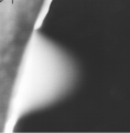 Air gas jet through 100 micron aperture into ESEM chamber held at 200 Pa, image taken with gaseous detection device, 15 kV
 -
 Greasy wool fibers going from wet to dry in ESEM, at room temperature. Field width=270 microns, BSE, 10 kV.
 -
 Resolution test specimen of gold particles on carbon in ESEM, at high magnification. Field width=1.2 microns


