Rack and pinion

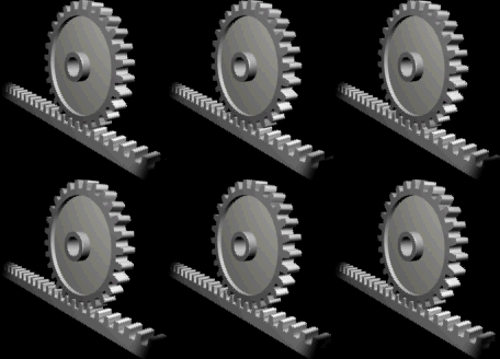
A rack and pinion is a pair of gears which convert rotational motion into linear motion. The circular pinion engages teeth on a flat bar - the rack. Rotational motion applied to the pinion will cause the rack to move to the side, up to the limit of its travel.
For example, in a rack railway, the rotation of a pinion mounted on a locomotive or a railcar engages a rack between the rails and pulls a train along a steep slope.
The rack and pinion arrangement is commonly found in the steering mechanism of cars or other wheeled, steered vehicles. This arrangement provides a lesser mechanical advantage than other mechanisms such as recirculating ball, but much less backlash and greater feedback, or steering "feel". The use of a variable rack was invented by Arthur E Bishop,[1] so as to improve vehicle response and steering "feel" on-centre, and that has been fitted to many new vehicles, after he created a hot forging process to manufacture the racks, thus eliminating any subsequent need to machine the form of the gear teeth.

For every pair of conjugate involute profile, there is a basic rack. This basic rack is the profile of the conjugate gear of infinite pitch radius.[2]
A generating rack is a rack outline used to indicate tooth details and dimensions for the design of a generating tool, such as a hob or a gear shaper cutter.[2]
External links
- Another animation of the rack and pinion mechanism.
References
- ^ "Rack and pinion variable ratio steering gear". Google Patent Search. Retrieved 2007-03-22.
- ^ a b ANSI/AGMA 1012-G05, "Gear Nomenclature, Definition of Terms with Symbols".
