Involute gear

The involute gear profile is the most commonly used system for gearing today. In an involute gear, the profiles of the teeth are involutes of a circle. (The involute of a circle is the spiraling curve traced by the end of an imaginary taut string unwinding itself from that stationary circle called the base circle.)
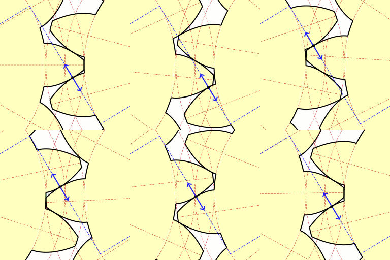
In involute gear design contact between a pair of gear teeth occurs at a single instantaneous point (see figure at right). Rotation of the gears causes the location of this contact point to move across the respective tooth surfaces. The path traced by this contact point is known as the Line of Action (also called Pressure Line or Line of Contact). A property of the involute tooth form is that if the gears are meshed properly, the line of action is straight and passes through the Pitch Point of the gears. When this is true, the gears obey the Fundamental Law of Gearing:[1]
The angular velocity ratio between two gears of a gearset must remain constant throughout the mesh.
This property results in smooth transmission of power without speed or torque variations as pairs of teeth go into or come out of mesh.
The Pressure Angle is the angle between the line of action and a normal to the line connecting the gear centers. The pressure angle of the gear is a function of the involute tooth shape and pairs of gears must have the same pressure angle in order for the teeth to mesh properly.
While any pressure angle can be manufactured, the most common found in stock gears are 14½° and 20°, with 25° pressure angle gears being much less common. Increasing the pressure angle increases the width of the base of the gear tooth, leading to greater strength and load carrying capacity. Decreasing the pressure angle provides lower backlash, smoother operation and less sensitivity to manufacturing errors.[2] In North America 14½° is the most commonly used pressure angle in stock gears while 20° is most common in other parts of the world.[citation needed]
References
- ^ Norton, R.L., 2006, Machine Design: An Integrated Approach, 3rd Ed, Pearson/Prentice-Hall, ISBN 0131481908
- ^ Boston Gear Company, Open Gearing Catalog, http://bostongear.com/products/open/spur.html
External links
- Kinematic Models for Design Digital Library (KMODDL)
Movies and photos of hundreds of working mechanical-systems models at Cornell University. Also includes an e-book library of classic texts on mechanical design and engineering.
