
Hart's inversors


Hart's inversor is one of two mechanisms that provides a perfect straight line motion without sliding guides.[1] They were invented and published by Harry Hart in 1874–5.[1][2]
Hart's first inversor is based on an antiparallelogram. The addition of fixed points and a driving arm make it a 6-bar linkage. It can be used to convert rotary motion to a perfect straight line by fixing a point on one short link and driving a point on another link in a circular arc.[1][3]
Hart's second inversor, also known as Hart's A-frame, is less flexible in its dimensions, but has the useful property that the motion perpendicularly bisects the fixed base points.
Example dimensions
-
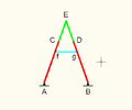
- AB = AC = BD = 4
- CE = ED = 2
- Af = Bg = 3
- fC = gD = 1
- fg = 2
-
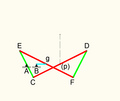
- AB = Bg = 2
- CE = FD = 6
- CA = AE = 3
- CD = EF = 12
- Cp = pD = Eg = gF = 6

.png)
See also
- Straight line mechanism
- Four-bar linkage
- Quadruplane inversor a generalization of Hart's first inversor
References
- ^ a b c "True straight-line linkages having a rectlinear translating bar" (PDF).
- ^ Ceccarelli, Marco (23 November 2007). International Symposium on History of Machines and Mechanisms. ISBN 9781402022043.
- ^ "Harts inversor (Has draggable animation)".
External links
Wikimedia Commons has media related to Hart's inversor.
- bham.ac.uk – Hart's A-frame (draggable animation) 6-bar linkage [dead link]
This engineering-related article is a stub. You can help Wikipedia by expanding it. |