
File:Zone plate boys.png

Original file (1,200 × 900 pixels, file size: 1.16 MB, MIME type: image/png)
| This is a file from the Wikimedia Commons. Information from its description page there is shown below. Commons is a freely licensed media file repository. You can help. |
Summary
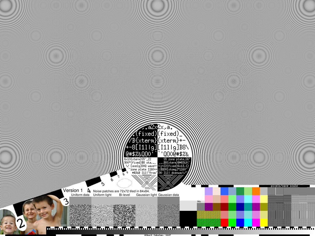
This is an image for testing LCD, plasma, OLED, and DLP displays on digital connections. It is less good (though still useful) with CRTs and VGA cables.
The image should be displayed as-is. The PNG is marked as being in the sRGB color space; your viewer should not mess with this. The image is correctly displayed when the grey noise patches match the grey reference colors right above them.
Some parts of the test image are for visual inspection, but many parts are to be photographed and measured. Use the best camera you have. To avoid vibration, use a tripod and either remote shutter or time-delay shutter. Take "camera raw" photos if you can, not just JPEG.
Start with a whole-screen photograph. Be sure to include all edges of the image, particularly the frequency scale at the bottom edge.
You'll need to take a few zoomed in images as well. Most cameras advertize subpixels rather than full pixels. You need to get multiple full camera pixels for each laptop subpixel. Nyquest's theories would suggest that you need 2x in each direction FOR AN INFINITE DISPLAY, but you'll need 4x or 5x to do a decent job. That's more like 10x when you're counting subpixels. So each subpixel of the screen should be covered by a 10x10 patch of subpixels in your camera.
This can be trouble. That is a LOT of images. To cut that down a tad, concentrate on:
- anything that looks defective
- each individual noise patch
- measurement markings, needed to locate items within the zone plate
It is probably a very good idea to take additional pictures of the test image on a second screen. This would be to determine which defects are caused by your camera, and which come from the screen being tested.
Be sure you have basic gamma, blackpoint, and whitepoint settings correct. The boys should look normal. The 75% grey patch should be sRGB value 225. The wide grey stripe below the text "bi-level" should have sRGB value 188; it is 50% grey.
Using the measurement markings along the bottom edge, locate the innermost non-central set of circles in the large grey zone-plate region. This will inform you about image frequency limits, here expressed as pixels/wave. The 3x1 areas of green and yellow diagonals should look all the same. The seven grey patches on the right of the top row should all look the same if you don't pay attention to the patterns. Likewise, there are two 3x4 regions that each should look uniform. (excepting borders) In the six rightmost columns of color patches, there should be no color! All must be grey. The greyscale strip along the bottom is 1024 wide, with one data step for every four pixels. The scales above are provided to help you count. Each noise patch should be as bright/dark as the grey area above it. It is hoped that the noise patches can be useful via an FFT; this has yet to be investigated.
Licensing

|
Permission is granted to copy, distribute and/or modify this document under the terms of the GNU Free Documentation License, Version 1.2 or any later version published by the Free Software Foundation; with no Invariant Sections, no Front-Cover Texts, and no Back-Cover Texts. A copy of the license is included in the section entitled GNU Free Documentation License. |
| This file is licensed under the Creative Commons Attribution-Share Alike 3.0 Unported license. | ||
| ||
| This licensing tag was added to this file as part of the GFDL licensing update. |
- You are free:
- to share – to copy, distribute and transmit the work
- to remix – to adapt the work
- Under the following conditions:
- attribution – You must give appropriate credit, provide a link to the license, and indicate if changes were made. You may do so in any reasonable manner, but not in any way that suggests the licensor endorses you or your use.
- share alike – If you remix, transform, or build upon the material, you must distribute your contributions under the same or compatible license as the original.
File history
Click on a date/time to view the file as it appeared at that time.
| Date/Time | Thumbnail | Dimensions | User | Comment | |
|---|---|---|---|---|---|
| current | 04:07, 26 February 2007 | | 1,200 × 900 (1.16 MB) | AlbertCahalan~commonswiki | This is an image for testing LCD, plasma, OLED, and DLP displays on digital connections. It is less good (though still useful) with CRTs and VGA cables. The image should be displayed as-is. The PNG is marked as being in the sRGB color space; your viewer |