Turbomachinery
This article needs additional citations for verification. (October 2015) |
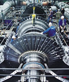
Turbomachinery, in mechanical engineering, describes machines that transfer energy between a rotor and a fluid, including both turbines and compressors. While a turbine transfers energy from a fluid to a rotor, a compressor transfers energy from a rotor to a fluid.[1][2]
These two types of machines are governed by the same basic relationships including Newton's second Law of Motion and Euler's energy equation for compressible fluids. Centrifugal pumps are also turbomachines that transfer energy from a rotor to a fluid, usually a liquid, while turbines and compressors usually work with a gas.[1]
Classification
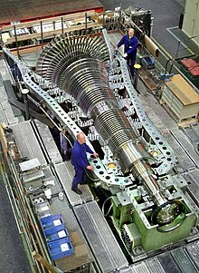
In general, the two kinds of turbomachines encountered in practice are open and closed turbomachines. Open machines such as propellers, windmills, and unshrouded fans act on an infinite extent of fluid, whereas, closed machines operate on a finite quantity of fluid as it passes through a housing or casing.[2]
Turbomachines are also categorized according to the type of flow. When the flow is parallel to the axis of rotation, they are called axial flow machines, and when flow is perpendicular to the axis of rotation, they are referred to as radial (or centrifugal) flow machines. There is also a third category, called mixed flow machines, where both radial and axial flow velocity components are present.[2]
Turbomachines may be further classified into two additional categories: those that absorb energy to increase the fluid pressure, i.e. pumps, fans, and compressors, and those that produce energy such as turbines by expanding flow to lower pressures. Of particular interest are applications which contain pumps, fans, compressors and turbines. These components are essential in almost all mechanical equipment systems, such as power and refrigeration cycles.[2][3]
| machine type → group ↓ |
machinery | combinations of power and machinery | engines |
|---|---|---|---|
| open turbomachine | propeller | wind turbines | |
| hydraulic fluid machinery (≈ incompressible fluids) |
centrifugal pumps turbopumps and fans |
Fluid couplings and clutches (hydrodynamic gearbox); Voith Turbo-Transmissions; pump-turbines (in pumped-storage hydroelectricity) |
water turbines |
| thermal turbomachinery (compressible fluid) |
compressors | gas turbines (inlet of GT consists of a compressor) |
steam turbines ← turbine jet engines |
Turbomachines
Definition
Any devices that extracts energy from or imparts energy to a continuously moving stream of fluid can be called a Turbomachine. Elaborating, a turbomachine is a power or head generating machine which employs the dynamic action of a rotating element, the rotor; the action of the rotor changes the energy level of the continuously flowing fluid through the machine. Turbines, compressors and fans are all members of this family of machines.[4]
In contrast to positive displacement machines (particulalrly of the reciprocating type which are low speed machines based on the mechanical and volumetric efficiency considerations), the majority of turbomachines run at comparatively higher speeds without any mechanical problems and volumetric efficiency close to one hundred percent.[5]
Categorization
Energy conversion
Turbomachines can be categorized on the basis of the direction of energy conversion:[1][2]
- Absorb power to increase the fluid pressure or head (ducted Fans, compressors and pumps).
- Produce power by expanding fluid to a lower pressure or head (hydraulic, steam and gas turbines).
Fluid flow
Turbomachines can be categorized on the basis of the nature of flow path through the passage of the rotor:[6]

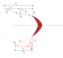
Axial Turbomachine's Velocity Diagram[1]
Axial flow turbomachines - When the path of the through-flow is wholly or mainly parallel to the axis of rotation, the device is termed an axial flow turbomachine.[7] The radial component of the fluid velocity is negligible. Since there is no change in the direction of the fluid, several axial stages can be used to increase power output.
A Kaplan turbine is an example of an axial flow turbine.
In the figure:
- U = Blade velocity,
- Vf = Flow velocity,
- V = Absolute velocity,
- Vr = Relative velocity,
- Vw = Tangential or Whirl component of velocity.
Radial Turbomachine's Velocity Diagram[1]
Radial flow turbomachines - When the path of the through-flow is wholly or mainly in a plane perpendicular to the rotation axis, the device is termed a radial flow turbomachine.[7] Therefore, the change of radius between the entry and the exit is finite. A Radial turbomachine can be inward or outward flow type depending on the purpose that needs to be served. Outward flow type increases the energy level of the fluid and vice versa. Due to continuous change in direction, several radial stages are generally not used.
A centrifugal pump is an example of a radial flow turbine.
In the figure:
- U = Blade velocity,
- Vf = Flow velocity,
- V = Absolute velocity,
- Vr = Relative velocity,
- Vw = Tangential or Whirl component of velocity.
Mixed flow turbomachines – When axial and radial flow are both present and neither is negligible, the device is termed a mixed flow turbomachine.[7] It combines flow and force components of both radial and axial types.
A Francis turbine is an example of a mixed-flow turbine.
Physical action
Turbomachines can finally be classified on the relative magnitude of the pressure changes that take place across a stage:[2][3]
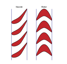
An Impulse Turbomachine Stage[1]
Impulse Turbomachines operate by accelerating and changing the flow direction of fluid through a stationary nozzle (the stator blade) onto the rotor blade. The nozzle serves to change the incoming pressure into velocity, the enthalpy of the fluid decreases as the velocity increases. Pressure and enthalpy drop over the rotor blades is minimal. Velocity will decrease over the rotor.[1][7]
Newton's second law describes the transfer of energy. Impulse turbomachines do not require a pressure casement around the rotor since the fluid jet is created by the nozzle prior to reaching the blading on the rotor.
A Pelton wheel is an impulse design.
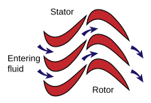
A Reaction Turbomachine Stage[1]
Reaction Turbomachines operate by reacting to the flow of fluid through aerofoil shaped rotor and stator blades. The velocity of the fluid through the sets of blades increases slightly (as with a nozzle) as it passes from rotor to stator and vice versa. The velocity of the fluid then decreases again once it has passed between the gap. Pressure and enthalpy consistently decrease through the sets of blades.[1]
Newton's third law describes the transfer of energy for reaction turbines. A pressure casement is needed to contain the working fluid. For compressible working fluids, multiple turbine stages are usually used to harness the expanding gas efficiently.
Most turbomachines use a combination of impulse and reaction in their design, often with impulse and reaction parts on the same blade.
Dimensionless ratios to describe turbomachinery

The following dimensionless ratios are often used for the characterisation of fluid machines. They allow a comparison of flow machines with different dimensions and boundary conditions.
- Pressure range ψ
- Flow number φ (including delivery or volume number called)
- Performance numbers λ
- Run number σ
- Diameter Number δ
Partial list of turbomachine topics
Many types of dynamic continuous flow turbomachinery exist. Below is a partial list of these types. What is notable about these turbomachines is that the same fundamentals apply to all. Certainly there are significant differences between these machines and between the types of analysis that are typically applied to specific cases. This does not negate the fact that they are unified by the same underlying physics of fluid dynamics, gas dynamics, aerodynamics, hydrodynamics, and thermodynamics.
- Axial compressor
- Axial fan
- Centrifugal compressor
- Centrifugal fan
- Centrifugal pump
- Centrifugal type supercharger
- Exoskeletal engine
- Francis turbine
- Gas turbine
- Industrial fans
- Jet engine
- Mechanical fan
- Mixed flow compressor
- Radial turbine
- Steam turbine
- Turbocharger
- Turboexpander
- Turbofans
- Turbojet
- Turboprop
- Turbopump
- Turboshaft
- Turbines
- Water turbine
See also
- Secondary flow in turbomachinery
- Slip factor
- Blade solidity
- Three-dimensional losses and correlation in turbomachinery
- Effects of mach number and shock losses in turbomachines
Sources
- S. M. Yahya. "Turbines Compressors and Fans". 1987. McGraw Hill.
References
- ^ a b c d e f g h i Logan, Earl. "Handbook of turbomachinery". 1995. Marcel Deckker.
- ^ a b c d e f Vandad Talimi (Original author unknown). "Mechanical Equipment and Systems". 2013. Memorial University of Newfoundland. http://www.engr.mun.ca/~yuri/Courses/MechanicalSystems/Turbomachinery.pdf
- ^ a b Baskharone, E. A. "Principles of Turbomachinery in Air-Breathing Engines". 2006. Cambridge University Press. 580 pages.
- ^ Rajadurai, J. S. "Thermodynamics and thermal engineering". 2003. New Age International. ISBN 81-224-1493-1
- ^ "Combining Support Vector Machines and Segmentation Algorithms for Efficient Anomaly Detection: A Petroleum Industry Application". International Joint Conference SOCO’14-CISIS’14-ICEUTE’14. 2014. pp.269-278. ISBN 978-3-319-07995-0
- ^ Wills, J. George. "Lubrication fundamentals". 1980. Mobil oil corporation. Marcel Dekker. 460 pages. ISBN 0-8247-6976-7
- ^ a b c d Dixon, S. L. "Fluid mechanics and thermodynamics of turbomachinery". 1998. Elsevier. 460 pages. ISBN 0-7506-7870-4
This article needs additional citations for verification. (November 2009) |


