Long Boiler locomotive


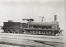
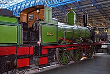
The long boiler locomotive was the object of a patent by Robert Stephenson and the name became synonymous with the pattern. Its defining feature is that the firebox is placed behind the rearmost driving axle. This gives a long boiler barrel, with long fire-tubes. There is thus a generous heating surface area, giving a boiler that is both powerful and efficient.
It is generally perceived that it arose out of attempts to match the power of broad gauge locomotives within the limitations of the standard gauge of Stephenson railways. However, the patent originally arose from a problem which became apparent as trains travelled longer distances, specifically on the North Midland Railway in England around 1841, where fire tubes and smokeboxes were becoming destroyed by the heat.
Experiments
Experiments at the North Midland's Derby Works showed temperatures as high as 773 °F (412 °C), determined by placing a small cup of zinc within the smokebox beneath the chimney. Stephenson extended the boiler, and hence the firetubes, from the usual nine feet to thirteen or fourteen feet. Placing tin in the smokebox, he found that it just began to melt, indicating a temperature of 442 °F (228 °C).
Stephenson's patent
Having tested the design on the North Midland line between Derby and Leeds, Stephenson took out a patent in 1842 for what he referred to as a "Long Boiler" engine. To protect his patent, he realised that he should not specify an exact length. Meanwhile, the prevailing view was that the centre of gravity should be as low as possible, which limited the size of the driving wheels, and incidentally precluded the use of inside cylinders.
Development

The initial locomotives were of 2-2-2 wheel arrangement to accommodate the extra length. However, with the outside cylinders, the engines were extremely unsteady, swaying from side to side. This led Stephenson to bring the rear wheels forward in the 4-2-0 formation, with the cylinders between the leading wheels. Such an engine was the "Great A" which took part in the Gauge Trials. This however, left the firebox behind the wheels and was therefore limited in size and weight. Moreover, the long rigid chassis made bends difficult to negotiate and damaged the track.
The classical long-boiler locomotive, then, was powerful but slow. Typically of 0-6-0 arrangement, it was ideal for goods trains, one example surviving is the NER 1001 Class another being Consett A Class A No.5.
Gray and Joy
The opposite point of view was taken by John Gray, who designed a number of engines for the London and Brighton Railway. His engines were the inspiration for David Joy in his design for the Jenny Lind locomotive, which compensated for the size of its boiler by greater efficiency and a pressure of some 120 psi.
Crampton
The long boiler design, on the other hand, was taken to its extreme by Thomas Russell Crampton in the Crampton locomotive which utilised a larger driving wheel by placing it behind the firebox.
References
- Lowe, J.W., (1989) British Steam Locomotive Builders, London: Guild Publishing
- Ransome, P.J.G., (1990) The Victorian Railway and How it Evolved, London: Heinemann
