
User:SecurityFanBoy/Continuous reactor
A Continuous reactor (alternatively referred to as a flow reactor) is a vessel that is used in the process industry for continuous operations of chemical reactions as they flow through the reactor. Continuous reactors may take many different forms with some having different components, but with all having a vessel to flow the reactants from at least one input until the product is ready to be produced at an outlet.
Comparison of batch and continuous reactors[edit]
Reactors can be divided into two broad categories, batch reactors and continuous reactors.[1][2][3][4]
Batch reactors are tanks sufficiently large to handle the full inventory of ingredients to complete a batch cycle. All of the reactants are charged into the batch reactor at the beginning of the process. At the end of the batch process, the product is removed from the batch reactor.
Continuous reactors react the reactants in a flowing stream through the continuous reactor where the product is created and discharged at the output of the reactor.
Overview[edit]
Raw materials, such as reactants are continuously fed into the inlet of a continuous reactor where the reaction starts. The reactants react as the materials flow through the reactor. In many cases, no additional materials are added during the process. The flow of the materials in the reactor vessel is set at a steady rate so that the reactants thoroughly react in the time that they are in the reactor. The reaction products are delivered from the reactor at the outlet.[1][2][3][4][5]
In addition to a vessel that contains the flowing materials, other components may be used in a continuous reactor. These components, such as thermal control, pressure control, and stirring and/or agitation, are designed into a continuous reactor by a process or chemical engineer using the principles of chemical kinetics. The engineer will design the process to achieve a goal. In most cases, the goal is to produce as much product as needed with the greatest efficiency. In some cases, the goal may be to optimize costs, such as to deliver specific amounts of product at the least cost.[6]
here
Design[edit]
Continuous reactors are usually in the shape of a cylinder or tube. The reactants are continuously loaded at one end where they mix and react as they flow along the length of the reactor. The products are removed at the other end of the reactor where they are separated from non-reactants, catalysts, and unreacted material. Other shapes that allow reactants to mix and react along a path may be used. Reactors must be configured to withstand the expected pressures, temperatures, and reactants without failing. Guidelines and certifications for the design and operational characteristics of reactors are provided by the American Society of Mechanical Engineers.[7]
here
In addition to understanding the reaction or process that will occur in a continuous reactor, a chemical or process engineer must configure the continuous reactor so that raw ingredients and products may be loaded (charged) at one end, and unloaded (discharged) from the other end of the continuous reactor.
Solids are usually charged from the top of the reactor using gravity to settle the solids to the bottom of the reactor. Liquids may also be charged from the top of the reactor unless contact with air and/or foaming is to be avoided. In those cases, liquids may be pumped into the reactor from the bottom.[2][1] If one of the reactants is a gas, it may be charged from the bottom through spargers so that it bubbles through the other fluids in the reactor.[1]
Once the reaction has completed, the product and non-reacted ingredients must be removed from the reactor. Gases may be discharged from the top, while liquids may be drained from the bottom. Solids are usually retrieved through a hatch in a side of the reactor.[4] The hatch may also be used by technicians to clean the reactor after the discharge.
Benefits of batch reactors[edit]
- Batch reactors are very versatile and are used for a variety for different unit operations (batch distillation, storage, crystallisation, liquid-liquid extraction etc.) in addition to chemical reactions.
- There is a large installed base of batch reactors within industry and their method of use is well established.
- Batch reactors are excellent at handling difficult materials like slurries or products with a tendency to foul.
- Batch reactors represent an effective and economic solution for many types of slow reactions.
Benefits of continuous reactors[edit]
- The rate of many chemical reactions is dependent on reactant concentration. Continuous reactors are generally able to cope with much higher reactant concentrations due to their superior heat transfer capacities. Plug flow reactors have the additional advantage of greater separation between reactants and products giving a better concentration profile.
- The small size of continuous reactors makes higher mixing rates possible.
- The output from a continuous reactor can be altered by varying the run time. This increases operating flexibility for manufacturers.
Heat transfer capacity[edit]
The rate of heat transfer within a reactor can be determined from the following relationship:

where:
- qx: the heat liberated or absorbed by the process (W)
- U: the heat transfer coefficient of the heat exchanger (W/(m2K))
- A: the heat transfer area (m2)
- Tp: process temperature (K)
- Tj: jacket temperature (K)
From a reactor design perspective, heat transfer capacity is heavily influenced by channel size since this determines the heat transfer area per unit volume. Channel size can be categorised in various ways however in broadest terms, the categories are as follows:
Industrial batch reactors : 1 – 10 m2/m3 (depending on reactor capacity)
Laboratory batch reactors : 10 – 100 m2/m3 (depending on reactor capacity)
Continuous reactors (non micro) : 100 - 5,000 m2/m3 (depending on channel size)
Micro reactors : 5,000 - 50,000 m2/m3 (depending on channel size)
Small diameter channels have the advantage of high heat transfer capacity. Against this however they have lower flow capacity, higher pressure drop and an increased tendency to block. In many cases, the physical structure and fabrication techniques for micro reactors make cleaning and unblocking very difficult to achieve.
Temperature control[edit]
Temperature control is one of key functions of a chemical reactor. Poor temperature control can severely affect both yield and product quality. It can also lead to boiling or freezing within the reactor which may stop the reactor from working altogether. In extreme cases, poor temperature control can lead to severe over pressure which can be destructive on the equipment and potentially dangerous.
Single stage systems with high heating or cooling flux[edit]
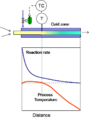
In a batch reactor, good temperature control is achieved when the heat added or removed by the heat exchange surface (qx) equals the heat generated or absorbed by the process material (qp). For flowing reactors made up of tubes or plates, satisfying the relationship qx = qp does not deliver good temperature control since the rate of process heat liberation/absorption varies at different points within the reactor. Controlling the outlet temperature does not prevent hot/cold spots within the reactor. Hot or cold spots caused by exothermic or endothermic activity can be eliminated by relocating the temperature sensor (T) to the point where the hot/cold spots exists. This however leads to overheating or overcooling downstream of the temperature sensor.
-
 Hot/cold spots are created when the reactor is treated as a single stage for temperature control
 -
 Hot/cold spots can be eliminated by moving the temperature sensor. This however causes overcooling or overheating downstream of the temperature sensor.


Many different types of plate or tube reactors use simple feed back control of the product temperature. From a user’s perspective, this approach is only suitable for processes where the effects of hot/cold spots do not compromise safety, quality or yield.
Single stage systems with low heating or cooling flux[edit]
Micro reactors can be tube or plates and have the key feature of small diameter flow channels (typically less than <1 mm). The significance of micro reactors is that the heat transfer area (A) per unit volume (of product) is very large. A large heat transfer area means that high values of qx can be achieved with low values of Tp – Tj. The low value of Tp – Tj limits the extent of over cooling that can occur. Thus the product temperature can be controlled by regulating the temperature of the heat transfer fluid (or the product).
-
 Overheating/overcooling is prevented by the limited temperature difference between the product and heat transfer fluid.

The feedback signal for controlling the process temperature can be the product temperature or the heat transfer fluid temperature. It is often more practical to control the temperature of the heat transfer fluid.
Although micro reactors are efficient heat transfer devices, the narrow channels can result in high pressure drops, limited flow capacity and a tendency to block. They are also often fabricated in a manner which makes cleaning and dismantling difficult or impossible.
Multistage systems with high heating or cooling flux[edit]
Conditions within a continuous reactor change as the product passes along the flow channel. In an ideal reactor the design of the flow channel is optimised to cope with this change. In practice, this is achieved by breaking the reactor into a series of stages. Within each stage the ideal heat transfer conditions can be achieved by varying the surface to volume ratio or the cooling/heating flux. Thus stages where process heat output is very high either use extreme heat transfer fluid temperatures or have high surface to volume ratios (or both). By tackling the problem as a series of stages, extreme cooling/heating conditions to be employed at the hot/cold spots without suffering overheating or overcooling elsewhere. The significance of this is that larger flow channels can be used. Larger flow channels are generally desirable as they permit higher rate, lower pressure drop and a reduced tendency to block.
Mixing[edit]
Mixing is another important classifying feature for continuous reactors. Good mixing improves the efficiency of heat and mass transfer.
In terms of trajectory through the reactor, the ideal flow condition for a continuous reactor is plug flow (since this delivers uniform residence time within the reactor). There is however a measure of conflict between good mixing and plug flow since mixing generates axial as well as radial movement of the fluid. In tube type reactors (with or without static mixing), adequate mixing can be achieved without seriously compromising plug flow. For this reason, these types of reactor are sometimes referred to as plug flow reactors.
Continuous reactors can be classified in terms of the mixing mechanism as follows:
Mixing by diffusion[edit]
Diffusion mixing relies on concentration or temperature gradients within the product. This approach is common with micro reactors where the channel thicknesses are very small and heat can be transmitted to and from the heat transfer surface by conduction. In larger channels and for some types of reaction mixture (especially immiscible fluids), mixing by diffusion is not practical.
-
 A simple tube can be used as a reactor. Small bore systems usually rely on mixing by diffusion

Mixing with the product transfer pump[edit]
In a continuous reactor, the product is continuously pumped through the reactor. This pump can also be used to promote mixing. If the fluid velocity is sufficiently high, turbulent flow conditions exist (which promotes mixing). The disadvantage with this approach is that it leads to long reactors with high pressure drops and high minimum flow rates. This is particularly true where the reaction is slow or the product has high viscosity. This problem can be reduced with the use of static mixers. Static mixers are baffles in the flow channel which are used to promote mixing. They are able to work with or without turbulent conditions. Static mixers can be effective but still require relatively long flow channels and generate relatively high pressure drops. The oscillatory baffled reactor is specialised form of static mixer where the direction of process flow is cycled. This permits static mixing with low net flow through the reactor. This has the benefit of allowing the reactor to be kept comparatively short.
-
 The static mixer permits mixing with or without turbulent conditions
 -
 The oscillatory baffled reactor uses a combination of static mixing and cycling of flow direction.


Mixing with a mechanical agitator[edit]
Some continuous reactors use mechanical agitation for mixing (rather than the product transfer pump). Whilst this adds complexity to the reactor design, it offers significant advantages in terms of versatility and performance. With independent agitation, efficient mixing can be maintained irrespective of product throughput or viscosity. It also eliminates the need for long flow channels and high pressure drops.
One less desirable feature associated with mechanical agitators is the strong axial mixing they generate. This problem can be managed by breaking up the reactor into a series of mixed stages separated by small plug flow channels.
The most familiar form of continuous reactor of this type is the continuously stirred tank reactor (CSTR). This is essentially a batch reactor used in a continuous flow. The disadvantage with a single stage CSTR is that it can be relatively wasteful on product during start up and shutdown. The reactants are also added to a mixture which is rich in product. For some types of process, this can affect quality and yield. These problems are managed by using multi stage CSTRs. At the large scale, conventional batch reactors can be used for the CSTR stages.
See also[edit]
- Chemical reactor
- Continuous reactor
- Semibatch reactor
- Continuous stirred-tank reactor
- Laminar flow reactor
References[edit]
- ^ a b Russell, T.; Robinson, A.; Wagner, N. (2008). Mass and Heat Transfer -ANALYSIS OF MASS CONTACTORS AND HEAT EXCHANGERS. Cambridge University Press. ISBN 978-0-521-88670-3.
- ^ a b Hill, C. (1977). AN INTRODUCTION TO CHEMICAL ENGINEERING KINETICS & REACTOR DESIGN. John Wiley & Sons, Inc. ISBN 0-471-39609-5.
- ^ a b Bieler, P. (2004). Analysis and Modelling of the Energy Consumption of Chemical Batch Plants (Report). Swiss Federal Office of Energy.
- ^ a b Perry, Robert (1997). Perry's Chemical Engineers' Handbook (Seventh ed.). McGraw Hill.
- ^ "Batch reactor". AIChE.
- ^ Schaber, SD; Gerogiorgis, DI; Ramachandran, R; Evans, JMB; Barton, PI; Trout, BL. "Economic Analysis of Integrated Continuous and Batch Pharmaceutical Manufacturing" (PDF). Industrial & Engineering Chemistry Research. 50, no. 17: 10083-10092. doi:10.1021/ie2006752.
- ^ "Boiler and Pressure Vessel Certification". ASME.