Single buoy mooring
This article needs additional citations for verification. (September 2014) |


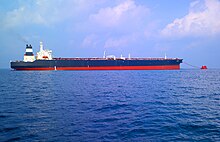
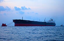
A Single buoy mooring (SrM) (also known as single-point mooring or SPM) is a loading buoy anchored offshore, that serves as a mooring point and interconnect for tankers loading or offloading gas or liquid products. SPMs are the link between geostatic subsea manifold connections and weathervaning tankers. They are capable of handling any tonnage ship, even very large crude carriers (VLCC) where no alternative facility is available.
In shallow water SPMs are used to load and unload crude oil and refined products from inshore and offshore oilfields or refineries, usually through some form of storage system. These buoys are usually suitable for use by all types of oil tanker. In deep water oil fields, SPMs are usually used to load crude oil direct from the production platforms, where there are economic reasons not to run a pipeline to the shore. These moorings usually supply to dedicated tankers which can moor without assistance.[1] Several types of single point mooring are in use.[1]
Parts
There are four groups of parts in the total mooring system: the body of the buoy, mooring and anchoring elements, product transfer system and other components.
Buoy body
The buoy body may be supported on static legs attached to the seabed, with a rotating part above water level connected to the (off)loading tanker. The two sections are linked by a roller bearing, referred to as the "main bearing". Alternatively the buoy body may be held in place by multiple radiating anchor chains. The moored tanker can freely weather vane around the buoy and find a stable position due to this arrangement.
Mooring and anchoring parts
Moorings fix the buoy to the sea bed. Buoy design must account for the behaviour of the buoy given applicable wind, wave and current conditions and tanker tonnages. This determines the optimum mooring arrangement and size of the various mooring leg components. Anchoring points are greatly dependent on local soil condition.[2]
Mooring components
- Anchors or piles - To connect the mooring to the seabed[2]
- Sinker or anchor chain joint to buoy (SPM)[2]
- Anchor chain[2]
- Chain stoppers - To connect the chains to the buoy[2]
Hawser arrangement
A tanker is moored to a buoy by means of a hawser arrangement. Oil Companies International Marine Forum (OCIMF) standards are available for mooring systems.
The hawser arrangement usually consist of nylon rope, which is shackled to an integrated mooring uni-joint on the buoy deck. At the tanker end of the hawser, a chafe chain is connected to prevent damage from the tanker fairlead. A load pin can be applied to the mooring uni-joint on the buoy deck to measure hawser loads.
Hawser systems use either one or two ropes depending on the largest tonnage of vessel which would be moored to the buoy. The ropes would either be single-leg or grommet leg type ropes. These are usually connected to an OCIMF chafe chain on the export tanker side (either type A or B depending on the maximum tonnage of the tanker and the mooring loads). This chafe chain would then be held in the chain stopper on board the export tanker.
A basic hawser system would consist of the following (working from the buoy outwards):
Buoy-side shackle and bridle assembly for connection to the padeye on the buoy; Mooring hawser shackle; Mooring hawser; Chafe chain assembly; Support buoy; Pick-up / messenger lines; Marker buoy for retrieval from the water.
Under OCIMF recommendations, the hawser arrangement would normally be purchased as a full assembly from a manufacturer.
Product transfer system
The heart of each buoy is the product transfer system. From a geostatic location, e.g. a pipeline end manifold (PLEM) located on the seabed, this system transfers products to the offtake tanker.
The basic product transfer system components are:
- Flexible subsea hoses, generally referred to as “risers”
- Floating hose string(s)
- Marine Breakaway Coupling
- Product swivel, valves and piping
Risers
The risers are flexible hoses that connect the subsea piping to the buoy. Configuration of these risers can vary depending on water depth, sea conditions, buoy motions, etc.
Floating hose string
Floating hose string(s) connect the buoy to the offloading tanker. The hose string can be equipped with a breakaway coupling to prevent rupture of hoses/hawser and subsequent oil spills.
Product swivel
The product swivel is the connection between the geostatic and the rotating parts of the buoy. The swivel enables an offloading tanker to rotate with respect to the mooring buoy. Product swivels range in size depending on the capacity of attached piping and risers. Product swivels can provide one or several independent paths for fluids, gases, electrical signals or power. Swivels are equipped with a multiple seal arrangement to minimise the possibility of leakage of product into the environment.
Other components
Other possible components of SPMs are:
- A boat landing, providing access to the buoy deck,
- Fendering to protect the buoy,
- Lifting and handling equipment to aid materials handling,
- Navigational aids for maritime visibility, and fog horn to keep moving vessel alert.
- An electrical subsystem to enable valve operation and to power navigation aids or other equipment.
Configurations

Catenary anchor leg mooring
A commonly used configuration is the catenary anchor leg mooring (CALM), which can be capable of handling very large crude carriers. This configuration uses six or eight heavy anchor chains placed radially around the buoy, of a tonnage to suit the designed load, each about 350 metres (1,150 ft) long, and attached to an anchor or pile to provide the required holding power. The anchor chains are pre-tensioned to ensure that the buoy is held in position above the PLEM. As the load from the tanker is applied, the heavy chains on the far side straighten and lift off the seabed to apply the balancing load. Under full design load there is still some 27 metres (89 ft) of chain lying on the bottom. The flexible hose riser may be in one of three basic configurations, all designed to accommodate tidal depth variation and lateral displacement due to mooring loads. In all cases the hose curvature changes to accommodate lateral and vertical movement of the buoy, and the hoses are supported at near neutral buoyancy by floats along the length. These are:[1]
- Chinese lantern, in which two to four mirror symmetrical hoses connect the PLEM with the buoy, with the convexity of the curve facing radially outwards.
- Lazy-S, in which the riser hose leaves the PLEM at a steep angle, then flattens out before gradually curving upwards to meet the buoy approximately vertically, in a flattened S-curve.
- Steep-S, in which the hose first rises roughly vertically to a submerged float, before making a sharp bend downwards followed by a slow curve through horizontal to a vertical attachment to the buoy.
Other configurations
Less commonly used configurations include:
- Single anchor leg mooring (SALM), which can be used in both shallow and deep water.[1] see Thistle SALM as an example.
- Vertical anchor leg mooring, which is seldom used.[1]
- Two types of single point mooring tower:
- Exposed location single buoy mooring (ELSBM). This configuration stores the mooring line and cargo hose on drums when not in use. Suitable for use in rough conditions[1]
- Articulated loading platform (ALP). Also suited for rough conditions.[1]
See also
- International Association of Marine Aids to Navigation and Lighthouse Authorities (IALA) – International association coordinating lighthouses and buoyage
