Luneburg lens

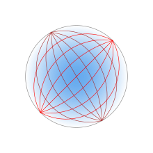
A Luneburg lens (originally Lüneburg lens, often incorrectly spelt Luneberg lens) is a spherically symmetric, variable-index refracting structure which will form perfect geometrical images of two given concentric spheres onto each other. The Luneburg lens is a spherical lens (usually a ball lens) generally having a gradient of decreasing refractive index n radially out from its center. The focusing properties of the Luneburg lens can be achieved through an infinite number of refractive-index solutions. The simplest such solution was proposed by Rudolf Luneburg in 1944.[1] Luneburg's solution for the refractive-index creates two conjugate foci outside of the lens. The solution takes a simple and explicit form if one focal point lies at infinity, and the other on the opposite surface of the lens. J. Brown and A. S. Gutman subsequently proposed solutions which generate one internal focal point and one external focal point.[2][3] These solutions are not unique; the set of solutions are defined by a set of definite integrals which must be evaluated numerically.[4]
Like a Luneburg lens, a gravitational lens also has a radially decreasing refractive index.
Luneburg's solution
Each point on the surface of an ideal Luneburg lens is the focal point for parallel radiation incident on the opposite side. Ideally, the dielectric constant of the material composing the lens falls from 2 at its center to 1 at its surface (or equivalently, the refractive index falls from to 1), according to
where is the radius of the lens. Because the refractive index at the surface is the same as a that of the surrounding medium, no reflection occurs at the surface. Within the lens, the paths of the rays are arcs of ellipses.
The practical implementation is normally a layered structure of discrete concentric shells, each of a different refractive index. These shells form a stepped refractive index profile that differs slightly from Luneburg's solution. This kind of lens is usually employed for microwave frequencies, especially to construct efficient microwave antennas and radar calibration standards.
Luneburg lens radar reflector
A radar reflector can be made from a Luneburg lens by metallizing parts of its surface. Radiation from a distant radar transmitter is focussed onto the underside of the metallization on the opposite side of the lens; here it is reflected, and focussed back onto the radar station. A difficulty with this scheme is that metallized regions block the entry or exit of radiation on that part of the lens, but the non-metallized regions result in a blind-spot on the opposite side.
Maxwell's fish-eye

Maxwell's fish-eye is also an example of the generalized Luneburg lens. The general fish-eye, which was described by Maxwell in 1854 (and therefore pre-dates Luneburg's solution), has a refractive index varying according to
- .
It focusses each point on the spherical surface of radius R to the opposite point on the same surface. Within the lens, the paths of the rays are arcs of circles.
Luneburg lens satellite antenna
A Luneburg lens made of polyethylene and polystyrene has been designed for train-mounted satellite dishes. The hemispherical Luneburg lens design is smaller and more reliable than traditional satellite dish antennas.[5][6]
See also
References
- ^ Luneburg, R. K. (1944). Mathematical Theory of Optics. Providence, Rhode Island: Brown University. pp. 189–213.
- ^ Brown, J. (1953). Wireless Engineer. 30: 250.
{{cite journal}}: Missing or empty|title=(help) - ^ Gutman, A. S. (1954). "Modified Luneberg Lens". J. Appl. Phys. 25: 855. doi:10.1063/1.1721757.
- ^ Morgan, S. P. (1958). "General solution of the Luneburg lens problem". J. Appl. Phys. 29: 1358–1368. doi:10.1063/1.1723441.
{{cite journal}}: Cite has empty unknown parameter:|coauthors=(help) - ^ Kremen, Rachel (December 30, 2008). "Broadband on Rails: A compact lens could make high-speed Internet access commonplace on trains". Technology Review. MIT. Retrieved 20 August 2009.
- ^ Caille, Gérard (2004). "Hemispherical Luneberg antenna motorized for satellite reception from the roof of a vehicle" (PDF). Retrieved August 20, 2009.
{{cite journal}}: Cite journal requires|journal=(help); Unknown parameter|coauthors=ignored (|author=suggested) (help)


