Stepper motor


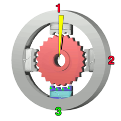
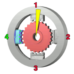
A stepper motor is a brushless, synchronous electric motor that can divide a full rotation into a large number of steps, for example, 200 steps.
This is achieved by increasing the numbers of poles (on both rotor and stator), taking care that they have no common denominator. Additionally, soft magnetic material with many teeth on the rotor and stator cheaply multiplies the number of poles (reluctance motor). Like an AC synchronous motor, it is ideally driven by sinusoidal current, allowing a stepless operation, but this puts some burden on the controller. When using an 8-bit digital controller, 256 microsteps per step are possible. As an analog-to-digital converter produces unwanted ohmic heat in the controller, pulse-width modulation is used instead to regulate the mean current. Simpler models switch voltage only for doing a step, thus needing an extra current limiter: for every step, they switch a single cable to the motor. Bipolar controllers can switch between supply voltage, ground, and unconnected. Unipolar controllers can only connect or disconnect a cable, because the voltage is already hard wired. Unipolar controllers need center-tapped windings.
Typically a bipolar stepper motor has 4 wires coming out of it. Each pair of wires is connected to the ends of two coils. The wires must be toggled between ground and voltage, which is usually accomplished via a set of transistors. Unipolar stepper motor has 5 or 6 wires. The extra wires are referred to as "common." They are located in the middle of the two coils and consistently supply voltage to the coils. The 4 wires that are located at the ends of the coils now switch between unconnected and ground. This helps reduce number of transistors required in the circuit. One way to distinguish common wire from a coil-end wire is by measuring the resistance. Resistance between common wire and coil-end wire is always half of what it is between coil-end and coil-end wires. This is due to the fact that there is actually twice the length of coil between the ends and only half from center (common wire) to the end.
It is possible to drive unipolar stepper motors with bipolar drivers. The idea is to connect the output pins of the driver to 4 transistors. The transistor must be grounded at the emitter and the driver pin must be connected to the base. Collector is connected to the coil wire of the motor.
Stepper motors are rated by the torque they produce. Syncron electric motors using soft magnetic materials (having a core) have the ability to provide position holding torque while not driven electrically. To achieve full rated torque, the coils in a stepper motor must reach their full rated current during each step. The voltage rating (if there is one) is almost meaningless. The motors also suffer from EMF, which means that once the coil is turned off it starts to generate current because the motor is still rotating. There needs to be an explicit way to handle this extra current in a circuit otherwise it can cause damage and affect performance of the motor.
Applications
Computer-controlled stepper motors are one of the most versatile forms of positioning systems, particularly when digitally controlled as part of a servo system. Stepper motors are used in floppy disk drives, flatbed scanners, printers, plotters and many more devices. Note that hard drives no longer use stepper motors, instead utilising a voice coil and servo feedback for head positioning.
Stepper motors can also be used for positioning of valve pilot stages, for fluid control systems.
