Modal analysis


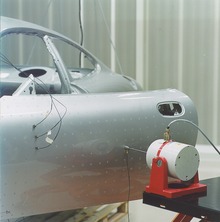
Modal analysis is the study of the dynamic properties of systems in the frequency domain. It consists of mechanically exciting a studied component in such a way to target the modeshapes of the structure, and recording the vibration data with a network of sensors. Examples would include measuring the vibration of a car's body when it is attached to a shaker, or the noise pattern in a room when excited by a loudspeaker.
Modern day experimental modal analysis systems are composed of 1) sensors such as transducers (typically accelerometers, load cells), or non contact via a Laser vibrometer, or stereophotogrammetric cameras 2) data acquisition system and an analog-to-digital converter front end (to digitize analog instrumentation signals) and 3) host PC (personal computer) to view the data and analyze it.
Classically this was done with a SIMO (single-input, multiple-output) approach, that is, one excitation point, and then the response is measured at many other points. In the past a hammer survey, using a fixed accelerometer and a roving hammer as excitation, gave a MISO (multiple-input, single-output) analysis, which is mathematically identical to SIMO, due to the principle of reciprocity. In recent years MIMO (multi-input, multiple-output) have become more practical, where partial coherence analysis identifies which part of the response comes from which excitation source. Using multiple shakers leads to a uniform distribution of the energy over the entire structure and a better coherence in the measurement. A single shaker may not effectively excite all the modes of a structure.[1]
Typical excitation signals can be classed as impulse, broadband, swept sine, chirp, and possibly others. Each has its own advantages and disadvantages.
The analysis of the signals typically relies on Fourier analysis. The resulting transfer function will show one or more resonances, whose characteristic mass, frequency and damping ratio can be estimated from the measurements.
The animated display of the mode shape is very useful to NVH (noise, vibration, and harshness) engineers.
The results can also be used to correlate with finite element analysis normal mode solutions.
Structures
In structural engineering, modal analysis uses the overall mass and stiffness of a structure to find the various periods at which it will naturally resonate. These periods of vibration are very important to note in earthquake engineering, as it is imperative that a building's natural frequency does not match the frequency of expected earthquakes in the region in which the building is to be constructed. If a structure's natural frequency matches an earthquake's frequency[citation needed], the structure may continue to resonate and experience structural damage. Modal analysis is also important in structures such as bridges where the engineer should attempt to keep the natural frequencies away from the frequencies of people walking on the bridge. This may not be possible and for this reasons when groups of people are to walk along a bridge, for example a group of soldiers, the recommendation is that they break their step to avoid possibly significant excitation frequencies. Other natural excitation frequencies may exist and may excite a bridge's natural modes. Engineers tend to learn from such examples (at least in the short term) and more modern suspension bridges take account of the potential influence of wind through the shape of the deck, which might be designed in aerodynamic terms to pull the deck down against the support of the structure rather than allow it to lift. Other aerodynamic loading issues are dealt with by minimizing the area of the structure projected to the oncoming wind and to reduce wind generated oscillations of, for example, the hangers in suspension bridges.
Although modal analysis is usually carried out by computers, it is possible to hand-calculate the period of vibration of any high-rise building through idealization as a fixed-ended cantilever with lumped masses.
Electrodynamics
The basic idea of a modal analysis in electrodynamics is the same as in mechanics. The application is to determine which electromagnetic wave modes can stand or propagate within conducting enclosures such as waveguides or resonators.
Superposition of modes
Once a set of modes has been calculated for a system, the response at any frequency (within certain bounds) to many inputs at many points with different time histories can be calculated by superimposing the result from each mode. This assumes the system is linear.
Reciprocity
If the response is measured at point B in direction x (for example), for an excitation at point A in direction y, then the transfer function (crudely Bx/Ay in the frequency domain) is identical to that which is obtained when the response at Ay is measured when excited at Bx. That is Bx/Ay=Ay/Bx. Again this assumes (and is a good test for) linearity. (Furthermore, this assumes restricted types of damping and restricted types of active feedback.)
Identification methods
Identification methods are the mathematical backbone of modal analysis. They allow, through linear algebra, specifically through least square methods to fit large amounts of data to find the modal constants (modal mass, modal stiffness modal damping) of the system. The methods are divided on the basis of the kind of system they aim to study in SDOF( single degree of freedom) methods and MDOF (multiple degree of freedom systems) methods and on the basis of the domain in which the data fitting takes place in time domain methods and frequency domain methods.
See also
- Frequency analysis
- Modal analysis using FEM
- Modeshape
- Eigenanalysis
- Structural dynamics
- Vibration
- Modal testing
- Seismic performance analysis
References
- D. J. Ewins: Modal Testing: Theory, Practice and Application
- Jimin He, Zhi-Fang Fu (2001). Modal Analysis, Butterworth-Heinemann. ISBN 0-7506-5079-6.
