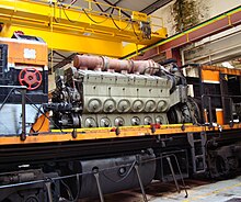
Prime mover (locomotive)

In engineering, a prime mover is an engine that converts fuel to useful work.[1] In locomotives, the prime mover is thus the source of power for its propulsion.[2] In an engine-generator set, the engine is the prime mover, as distinct from the generator.
Definition
In a diesel-mechanical locomotive, the prime mover is the diesel engine that is mechanically coupled to the driving wheels (drivers). In a diesel-electric locomotive, the prime mover is the diesel engine that rotates the main generator responsible for producing electricity to power the traction motors that are geared to the drivers. The prime mover can also be a gas turbine instead of a diesel engine. In either case, the generator, traction motors and interconnecting apparatus are considered to be the power transmission system and not part of the prime mover. A wired-electric or battery-electric locomotive has no on-board prime mover, instead relying on an external power station.
Power unit

The engine (prime mover) and generator set of a diesel-electric locomotive are sometimes coupled as a removable unit called "the power unit".[3] Although the mechanical forces between engine and generator are large, there are no forces other than weight from the power unit group to the locomotive chassis. This allows the group to be mounted on light anti-vibration mounts, such as a three-point suspension.[4]
Weight distribution
The power unit represents the main weight in a locomotive design, other than the chassis or body. Its position back and forth is at the designer's choice and may be used to control overall weight distribution. In most locomotives designs, the power unit is placed centrally. In some locomotives, it is offset to one end, or the heavier engine is outboard of the generator. In extreme cases, such as C-B wheel arrangements, the weight on each bogie may differ so much that the engine-end bogie is given an extra carrying axle, to keep individual axle loads more consistent.[5]
See also
References
- ^ Kennedy, Rankin (1905). The Book of Modern Engines and Power Generators. Vol. Vol I. London: Caxton. p. 33.
{{cite book}}:|volume=has extra text (help) - ^ Boyle, Bryan 'Bob' (2000). The Napier Way. Bookmarque Publishing. p. 149. ISBN 1-870519-57-4.
- ^ Chapman, C.W. (1956). Modern High-Speed Oil Engines. Vol. Vol II (2nd ed.). Caxton. pp. 73–74.
{{cite book}}:|volume=has extra text (help) - ^ "Locomotives for Nigeria and Gold Coast". Vulcan Magazine. Vol. Vol 3, no. 6. Summer 1955. pp. 18–19.
{{cite magazine}}:|volume=has extra text (help) - ^ Carter, R.S. (1963). "Metropolitan-Vickers (AEI) diesel-electric Co-Bo Type 2 (BR Class 28)". British Railways Main-Line Diesels. Ian Allan. pp. 22–23.
