Airfoil

An airfoil (in American English) or aerofoil (in British English) is the shape of a wing or blade (of a propeller, rotor, or turbine) or sail as seen in cross-section.
An airfoil-shaped body moved through a fluid produces an aerodynamic force. The component of this force perpendicular to the direction of motion is called lift. The component parallel to the direction of motion is called drag. Subsonic flight airfoils have a characteristic shape with a rounded leading edge, followed by a sharp trailing edge, often with asymmetric camber. Foils of similar function designed with water as the working fluid are called hydrofoils.
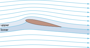
The lift on an airfoil is primarily the result of its angle of attack and shape. When oriented at a suitable angle, the airfoil deflects the oncoming air, resulting in a force on the airfoil in the direction opposite to the deflection. This force is known as aerodynamic force and can be resolved into two components: Lift and drag. Most foil shapes require a positive angle of attack to generate lift, but cambered airfoils can generate lift at zero angle of attack. This "turning" of the air in the vicinity of the airfoil creates curved streamlines which results in lower pressure on one side and higher pressure on the other. This pressure difference is accompanied by a velocity difference, via Bernoulli's principle, so the resulting flowfield about the airfoil has a higher average velocity on the upper surface than on the lower surface. The lift force can be related directly to the average top/bottom velocity difference without computing the pressure by using the concept of circulation and the Kutta-Joukowski theorem.[1][2][3][4]
Introduction


A fixed-wing aircraft's wings, horizontal, and vertical stabilizers are built with airfoil-shaped cross sections, as are helicopter rotor blades. Airfoils are also found in propellers, fans, compressors and turbines. Sails are also airfoils, and the underwater surfaces of sailboats, such as the centerboard and keel, are similar in cross-section and operate on the same principles as airfoils. Swimming and flying creatures and even many plants and sessile organisms employ airfoils/hydrofoils: common examples being bird wings, the bodies of fish, and the shape of sand dollars. An airfoil-shaped wing can create downforce on an automobile or other motor vehicle, improving traction.
Any object with an angle of attack in a moving fluid, such as a flat plate, a building, or the deck of a bridge, will generate an aerodynamic force (called lift) perpendicular to the flow. Airfoils are more efficient lifting shapes, able to generate more lift (up to a point), and to generate lift with less drag.
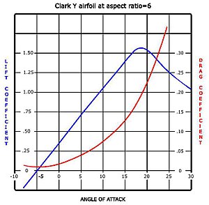
A lift and drag curve obtained in wind tunnel testing is shown on the right. The curve represents an airfoil with a positive camber so some lift is produced at zero angle of attack. With increased angle of attack, lift increases in a roughly linear relation, called the slope of the lift curve. At about 18 degrees this airfoil stalls, and lift falls off quickly beyond that. The drop in lift can be explained by the action of the upper-surface boundary layer, which separates and greatly thickens over the upper surface at and past the stall angle. The thickened boundary layer's displacement thickness changes the airfoil's effective shape, in particular it reduces its effective camber, which modifies the overall flow field so as to reduce the circulation and the lift. The thicker boundary layer also causes a large increase in pressure drag, so that the overall drag increases sharply near and past the stall point.
Airfoil design is a major facet of aerodynamics. Various airfoils serve different flight regimes. Asymmetric airfoils can generate lift at zero angle of attack, while a symmetric airfoil may better suit frequent inverted flight as in an aerobatic airplane. In the region of the ailerons and near a wingtip a symmetric airfoil can be used to increase the range of angles of attack to avoid spin-stall. Thus a large range of angles can be used without boundary layer separation. Subsonic airfoils have a round leading edge, which is naturally insensitive to the angle of attack. The cross section is not strictly circular, however: the radius of curvature is increased before the wing achieves maximum thickness to minimize the chance of boundary layer separation. This elongates the wing and moves the point of maximum thickness back from the leading edge.
Supersonic airfoils are much more angular in shape and can have a very sharp leading edge, which is very sensitive to angle of attack. A supercritical airfoil has its maximum thickness close to the leading edge to have a lot of length to slowly shock the supersonic flow back to subsonic speeds. Generally such transonic airfoils and also the supersonic airfoils have a low camber to reduce drag divergence. Modern aircraft wings may have different airfoil sections along the wing span, each one optimized for the conditions in each section of the wing.
Movable high-lift devices, flaps and sometimes slats, are fitted to airfoils on almost every aircraft. A trailing edge flap acts similarly to an aileron; however, it, as opposed to an aileron, can be retracted partially into the wing if not used.
A laminar flow wing has a maximum thickness in the middle camber line. Analyzing the Navier-Stokes equations in the linear regime shows that a negative pressure gradient along the flow has the same effect as reducing the speed. So with the maximum camber in the middle, maintaining a laminar flow over a larger percentage of the wing at a higher cruising speed is possible. However, with rain or insects on the wing, or for jetliner speeds, this does not work. Since such a wing stalls more easily, this airfoil is not used on wingtips (spin-stall again).
Schemes have been devised to define airfoils — an example is the NACA system. Various airfoil generation systems are also used. An example of a general purpose airfoil that finds wide application, and predates the NACA system, is the Clark-Y. Today, airfoils can be designed for specific functions using inverse design programs such as PROFOIL, XFOIL and AeroFoil. XFOIL is an online program created by Mark Drela that will design and analyze subsonic isolated airfoils.[5]
Airfoil terminology

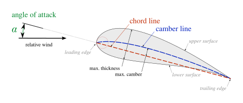
The various terms related to airfoils are defined below:[6]
- The suction surface (a.k.a. upper surface) is generally associated with higher velocity and lower static pressure.
- The pressure surface (a.k.a. lower surface) has a comparatively higher static pressure than the suction surface. The pressure gradient between these two surfaces contributes to the lift force generated for a given airfoil.
The geometry of the airfoil is described with a variety of terms.
A key characteristic of an airfoil is its chord. We thus define the following concepts:
- The leading edge is the point at the front of the airfoil that has maximum curvature.[7]
- The trailing edge is defined similarly as the point of maximum curvature at the rear of the airfoil.
- The chord line is a straight line connecting the leading and trailing edges of the airfoil.
- The chord length, or simply chord, , is the length of the chord line and is the characteristic dimension of the airfoil section.


The shape of the airfoil is defined using the following concepts:
- The mean camber line is the locus of points midway between the upper and lower surfaces. Its exact shape depends on how the thickness is defined;
- The thickness of an airfoil varies along the chord. It may be measured in either of two ways:
Two key parameters to describe an airfoil’s shape are its maximum thickness (expressed as a percentage of the chord), and the location of the maximum thickness point (also expressed as a percentage of the chord).
Finally, important concepts used to describe the airfoil’s behavior when moving through a fluid are:
- The aerodynamic center, which is the chord-wise length about which the pitching moment is independent of the lift coefficient and the angle of attack.
- The center of pressure, which is the chord-wise location about which the pitching moment is zero.
Thin airfoil theory


Thin airfoil theory is a simple theory of airfoils that relates angle of attack to lift for incompressible, inviscid flows. It was devised by German-American mathematician Max Munk and further refined by British aerodynamicist Hermann Glauert and others[11] in the 1920s. The theory idealizes the flow around an airfoil as two-dimensional flow around a thin airfoil. It can be imagined as addressing an airfoil of zero thickness and infinite wingspan.
Thin airfoil theory was particularly notable in its day because it provided a sound theoretical basis for the following important properties of airfoils in two-dimensional flow:[12][13]
(1) on a symmetric airfoil, the center of pressure and aerodynamic center lies exactly one quarter of the chord behind the leading edge
(2) on a cambered airfoil, the aerodynamic center lies exactly one quarter of the chord behind the leading edge
(3) the slope of the lift coefficient versus angle of attack line is units per radian
As a consequence of (3), the section lift coefficient of a symmetric airfoil of infinite wingspan is:
- where is the section lift coefficient,
- is the angle of attack in radians, measured relative to the chord line.
(The above expression is also applicable to a cambered airfoil where is the angle of attack measured relative to the zero-lift line instead of the chord line.)
Also as a consequence of (3), the section lift coefficient of a cambered airfoil of infinite wingspan is:
- where is the section lift coefficient when the angle of attack is zero.
Thin airfoil theory does not account for the stall of the airfoil, which usually occurs at an angle of attack between 10° and 15° for typical airfoils.[14]
Derivation of thin airfoil theory

• Laminar flow airfoil for a RC park flyer
• Laminar flow airfoil for a RC pylon racer
• Laminar flow airfoil for a manned propeller aircraft
• Laminar flow at a jet airliner airfoil
• Stable airfoil used for flying wings
• Aft loaded airfoil allowing for a large main spar and late stall
• Transonic supercritical airfoil
• Supersonic leading edge airfoil
Colors:
Black = laminar flow,
red = turbulent flow,
grey = subsonic stream,
blue = supersonic flow volume
The airfoil is modeled as a thin lifting mean-line (camber line). The mean-line, y(x), is considered to produce a distribution of vorticity along the line, s. By the Kutta condition, the vorticity is zero at the trailing edge. Since the airfoil is thin, x (chord position) can be used instead of s, and all angles can be approximated as small.
From the Biot-Savart law, this vorticity produces a flow field where
where is the location where induced velocity is produced, is the location of the vortex element producing the velocity and is the chord length of the airfoil.
Since there is no flow normal to the curved surface of the airfoil, balances that from the component of main flow , which is locally normal to the plate—the main flow is locally inclined to the plate by an angle . That is:
This integral equation can by solved for , after replacing x by
- ,
as a Fourier series in with a modified lead term
That is
(These terms are known as the Glauert integral).
The coefficients are given by
and
By the Kutta–Joukowski theorem, the total lift force F is proportional to
and its moment M about the leading edge to
The calculated Lift coefficient depends only on the first two terms of the Fourier series, as
The moment M about the leading edge depends only on and , as
The moment about the 1/4 chord point will thus be,
- .
From this it follows that the center of pressure is aft of the 'quarter-chord' point 0.25 c, by
The aerodynamic center, AC, is at the quarter-chord point. The AC is where the pitching moment M' does not vary with angle of attack, i.e.,
See also
- Aquanator
- Circulation control wing
- Coefficient of lift
- Hydrofoil
- Kline Fogleman airfoil
- Küssner effect
- Lift (force)
- NACA airfoil
- Parafoil
- Stall (flight)
- Supersonic airfoils
Notes
- ^ "...the effect of the wing is to give the air stream a downward velocity component. The reaction force of the deflected air mass must then act on the wing to give it an equal and opposite upward component." In: Halliday, David; Resnick, Robert, Fundamentals of Physics 3rd Edition, John Wiley & Sons, p. 378
- ^ "If the body is shaped, moved, or inclined in such a way as to produce a net deflection or turning of the flow, the local velocity is changed in magnitude, direction, or both. Changing the velocity creates a net force on the body" "Lift from Flow Turning". NASA Glenn Research Center. Archived from the original on 5 July 2011. Retrieved 2011-06-29.
{{cite web}}: Unknown parameter|deadurl=ignored (|url-status=suggested) (help) - ^ "The cause of the aerodynamic lifting force is the downward acceleration of air by the airfoil..." Weltner, Klaus; Ingelman-Sundberg, Martin, Physics of Flight - reviewed
- ^ "...if a streamline is curved, there must be a pressure gradient across the streamline..."Babinsky, Holger (2003), "How do wings work?" (PDF), Physics Education
{{citation}}: Unknown parameter|month=ignored (help) - ^ XFOIL
- ^ Hurt, H. H., Jr. (1965) [1960]. Aerodynamics for Naval Aviators. U.S. Government Printing Office, Washington D.C.: U.S. Navy, Aviation Training Division. pp. 21–22. NAVWEPS 00-80T-80.
{{cite book}}: Unknown parameter|month=ignored (help)CS1 maint: multiple names: authors list (link) - ^ Houghton, E. L.; Carpenter, P.W. (2003). Butterworth Heinmann (ed.). Aerodynamics for Engineering Students (5th ed.). ISBN 0-7506-5111-3.
{{cite book}}: CS1 maint: multiple names: authors list (link) p.18 - ^ a b Houghton, E. L.; Carpenter, P.W. (2003). Butterworth Heinmann (ed.). Aerodynamics for Engineering Students (5th ed.). ISBN 0-7506-5111-3.
{{cite book}}: CS1 maint: multiple names: authors list (link) p.17 - ^ Phillips, Warren F. (2010). Mechanics of Flight (2nd ed.). Wiley & Sons. ISBN 978-0-470-53975-0. p.27
- ^ Bertin, John J.; Cummings, Russel M. (2009). Pearson Prentice Hall (ed.). Aerodynamics for Engineers (5th ed.). ISBN 978-0-13-227268-1.
{{cite book}}: CS1 maint: multiple names: authors list (link) p.199 - ^ Abbott, Ira H., and Von Doenhoff, Albert E. (1959), Theory of Wing Sections, Section 4.2, Dover Publications Inc., New York, Standard Book Number 486-60586-8
- ^ Abbott, Ira H., and Von Doenhoff, Albert E. (1959), Theory of Wing Sections, Section 4.3
- ^ Clancy, L.J. (1975), Aerodynamics, Sections 8.1 to 8.8, Pitman Publishing Limited, London. ISBN 0-273-01120-0
- ^ Aerospaceweb's information on Thin Airfoil Theory
References
- Anderson, John, D (2007). Fundamentals of Aerodynamics. McGraw-Hill.
{{cite book}}: CS1 maint: multiple names: authors list (link) - Desktopaero
- University of Sydney, Aerodynamics for Students
- Batchelor, George. K (1967). An Introduction to Fluid Dynamics. Cambridge UP. pp. 467–471.
External links
- UIUC Airfoil Coordinates Database
- Database with airfoils
- Airfoil & Hydrofoil Reference Application
- The Joukowski Airfoil
- Chard Museum The Birth of Powered Flight.
- FoilSim An airfoil simulator from NASA.
- NACA Project Application to draw airfoil sections in Autocad and DraftSight.


