Dielectric mirror

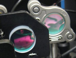
A dielectric mirror, also known as a Bragg mirror, is a type of mirror composed of multiple thin layers of dielectric material, typically deposited on a substrate of glass or some other optical material. By careful choice of the type and thickness of the dielectric layers, one can design an optical coating with specified reflectivity at different wavelengths of light. Dielectric mirrors are also used to produce ultra-high reflectivity mirrors: values of 99.999% or better over a narrow range of wavelengths can be produced using special techniques. Alternatively, they can be made to reflect a broad spectrum of light, such as the entire visible range or the spectrum of the Ti-sapphire laser. Mirrors of this type are very common in optics experiments, due to improved techniques that allow inexpensive manufacture of high-quality mirrors. Examples of their applications include laser cavity end mirrors, hot and cold mirrors, thin-film beamsplitters, and the coatings on modern mirrorshades.
Mechanism

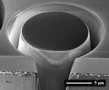
Dielectric mirrors function based on the interference of light reflected from the different layers of dielectric stack. This is the same principle used in multi-layer anti-reflection coatings, which are dielectric stacks which have been designed to minimize rather than maximize reflectivity. Simple dielectric mirrors function like one-dimensional photonic crystals, consisting of a stack of layers with a high refractive index interleaved with layers of a low refractive index (see diagram). The thicknesses of the layers are chosen such that the path-length differences for reflections from different high-index layers are integer multiples of the wavelength for which the mirror is designed. The reflections from the low-index layers have exactly half a wavelength in path length difference, but there is a 180-degree difference in phase shift at a low-to-high index boundary, compared to a high-to-low index boundary, which means that these reflections are also in phase. In the case of a mirror at normal incidence, the layers have a thickness of a quarter wavelength.

Other designs have a more complicated structure generally produced by numerical optimization. In the latter case, the phase dispersion of the reflected light can also be controlled (see Chirped mirror). In the design of dielectric mirrors, an optical transfer-matrix method can be used.
Dielectric mirrors exhibit retardance as a function of angle of incidence and mirror design.[1]
Manufacturing

The manufacturing techniques for dielectric mirrors are based on thin-film deposition methods. Common techniques are physical vapor deposition (which includes evaporative deposition and ion beam assisted deposition), chemical vapor deposition, ion beam deposition, molecular beam epitaxy, and sputter deposition. Common materials are magnesium fluoride, silicon dioxide, tantalum pentoxide, zinc sulfide (n=2.32), and titanium dioxide (n=2.4).
See also
References
- ^ "Phase retardance of periodic multilayer mirrors",J. H. Apfel Applied Optics 21, 733-738 (1982)
