XOR gate
| INPUT A B |
OUTPUT A XOR B | |
| 0 | 0 | 0 |
| 0 | 1 | 1 |
| 1 | 0 | 1 |
| 1 | 1 | 0 |
The XOR gate (sometimes EOR gate, or EXOR gate) is a digital logic gate that implements an exclusive disjunction; that is, it behaves according to the truth table shown on the right. A true output (1) results if one, and only one, of the inputs to the gate is true (1). If both inputs are false (0) or both are true (1), a false output (0) results. A way to remember XOR is "one or the other but not both". It represents the inequality function, i.e., the output is HIGH (1) if the inputs are not alike otherwise the output is LOW (0).
This function is addition modulo 2. As a result, XOR gates are used to implement binary addition in computers. A half adder consists of an XOR gate and an AND gate.
Symbols
There are two symbols for XOR gates: the 'military' symbol which was originally developed in America and the 'rectangular' symbol, which was originally British. For more information see Logic Gate Symbols.


The XOR gate with inputs A and B implements the logical expression .
Hardware description and pinout
XOR gates are basic logic gates, and as such they are recognised in TTL and CMOS ICs. The standard 4000 series CMOS IC is the 4070, which includes four independent two-input XOR gates. The 4070 replaces the less reliable 4030, but keeps the pinout. The pinout diagram is as follows:
 1  Input A1
 2  Input B1
 3  Output Q1
 4  Output Q2
 5  Input A2
 6  Input B2
7 VG 8 Input A3 9 Input B3 10 Output Q3 11 Output Q4 12 Input A4 13 Input B4 14 VCC |
This device is available from most semiconductor manufacturers such as NXP. It is usually available in both through-hole DIL and SOIC format. Datasheets are readily available in most Datasheet Databases.
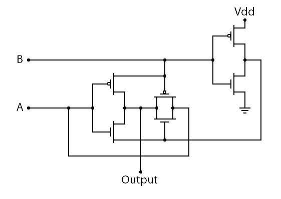
Transmission-Gate-Logic Wiring
An XOR gate can be constructed using MOSFETs. Here is a diagram of the transmission gate implementation of an XOR Gate.[1]

Alternatives
If a specific type of gate is not available, it can be constructed from other available gates. An XOR gate can be trivially constructed from an XNOR gate followed by a NOT gate. If we consider the expression , we can construct an XOR gate directly using AND, OR and NOT gates. However, this approach requires five gates of three different kinds.
An XOR gate can be made from four NAND or five NOR gates in the configurations shown below. In fact, both NAND and NOR gates are so-called "universal gates," and any logical function can be constructed from either NAND logic or NOR logic alone.
 |
 |
More than two inputs
Strict reading of the definition of exclusive or, or observation of the IEC symbol, raises the question of correct behaviour with additional inputs. If a logic gate were to accept three or more inputs and produce a true output if exactly one of those inputs were true, then it would in effect be a one-hot detector (and indeed this is the case for only two inputs). However, it is rarely implemented this way in practice.
It is most common to regard subsequent inputs as being applied through a cascade of binary exclusive-or operations: the first two signals are fed into an XOR gate, then the output of that gate is fed into a second XOR gate together with the third signal, and so on for any remaining signals. The result is a circuit that outputs a 1 when the number of 1s at its inputs is odd, and a 0 when the number of incoming 1s is even. This makes it practically useful as a parity generator or a modulo-2 adder.
For example, the 74LVC1G386 microchip is advertised as a three-input logic gate, and implements a parity generator[2].
The Verilog reduction operators can also take an arbitrary number of single-bit inputs into a single exclusive-or operation, producing a single-bit result. Here the output is also defined as a parity operation[citation needed].
Applications
Uses in Addition
The XOR logic gate can be used as a one-bit adder. This will add any two bits together to output one. If both of the input values are 1, therefore giving a 10 answer, an AND gate can be used on both of the values to give the carry bit. This is the main principle in Half Adders.

Signal crossing
XOR gates can be used to cross two Boolean signals without requiring a via. The crossover comprises three XOR gates, strategically positioned to cancel out the effects of each other. A similar result can be achieved using eight NAND gates. Note that this setup can only cross Boolean (digital) signals, and not analog signals, so would be of limited use in an amplifier or other analog circuit.

Pseudo-random number generation
Pseudo-random number generators, specifically Linear feedback shift registers, are defined in terms of the exclusive-or operation. Hence, a suitable setup of XOR gates can model a linear feedback shift register, in order to generate random sequences of bits.


