Voltage-controlled oscillator
A voltage-controlled oscillator or VCO is an electronic oscillator whose oscillation frequency is controlled by a voltage input. The applied input voltage determines the instantaneous oscillation frequency. Consequently, modulating signals applied to control input may cause frequency modulation (FM) or phase modulation (PM). A VCO may also be part of a phase-locked loop.

Types of VCO
VCOs can be generally categorized into two groups based on the type of waveform produced.
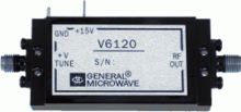
- Linear or harmonic oscillators generate a sinusoidal waveform. Harmonic oscillators in electronics usually consist of a resonator with an amplifier that replaces the resonator losses (to prevent the amplitude from decaying) and isolates the resonator from the output (so the load does not affect the resonator). Some examples of harmonic oscillators are LC-tank oscillators and crystal oscillators. In a voltage-controlled oscillator, a voltage input controls the resonant frequency. A varactor diode's capacitance is controlled by the voltage across the diode. Consequently, a varactor can be used to change the capacitance (and hence the frequency) of an LC tank. A varactor can also change ("pull") the resonant frequency of a crystal resonator.
- Relaxation oscillators can generate a sawtooth or triangular waveform. They are commonly used in monolithic integrated circuits (ICs). They can provide a wide range of operational frequencies with a minimal number of external components. Relaxation oscillator VCOs can have three topologies: 1) grounded-capacitor VCOs, 2) emitter-coupled VCOs, and 3) delay-based ring VCOs.[dubious – discuss] The first two of these types operate similarly. The time spent in each state depends on the rate of charge or discharge of a capacitor. The delay-based ring VCO operates somewhat differently however. For this type, the gain stages are connected in a ring. The output frequency is then a function of the delay in each stage.
Harmonic oscillator VCOs have these advantages over relaxation oscillators:
- Frequency stability with respect to temperature, noise, and power supply is much better for harmonic oscillator VCOs.
- They have good accuracy for frequency control since the frequency is controlled by a crystal or tank circuit.[dubious – discuss]
A disadvantage of harmonic oscillator VCOs is that they cannot be easily implemented in monolithic ICs.[dubious – discuss] Relaxation oscillator VCOs are better suited for this technology.[citation needed] Relaxation VCOs are also tunable over a wider range of frequencies.
Control of frequency in VCOs

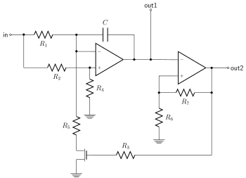
A voltage-controlled capacitor is one method of making an LC oscillator vary its frequency in response to a control voltage. Any reverse-biased semiconductor diode displays a measure of voltage-dependent capacitance and can be used to change the frequency of an oscillator by varying a control voltage applied to the diode. Special-purpose variable capacitance varactor diodes are available with well-characterized wide-ranging values of capacitance. Such devices are very convenient in the manufacture of voltage-controlled oscillators.[note 1] For low-frequency VCOs, other methods of varying the frequency (such as altering the charging rate of a capacitor by means of a voltage controlled current source) are used (see function generator).
The frequency of a ring oscillator is controlled by varying either the supply voltage, the current available to each inverter stage, or the capacitive loading on each stage.
Voltage-controlled crystal oscillators
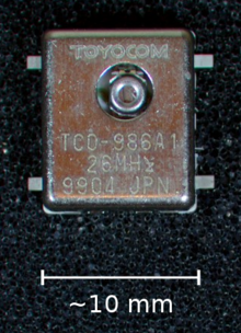
A voltage-controlled crystal oscillator (VCXO) is used for fine adjustment of the operating frequency. The frequency of a voltage-controlled crystal oscillator can be varied a few tens of parts per million (ppm), because the high Q factor of the crystals allows "pulling" over only a small range of frequencies.
There are two reasons for using a VCXO:
- To adjust the output frequency to match or perhaps be some exact multiple of an accurate external reference.
- Where the oscillator drives equipment that may generate radio-frequency interference, adding a varying voltage to its control input can disperse the interference spectrum to make it less objectionable (see spread spectrum clock).

A temperature-compensated VCXO (TCVCXO) incorporates components that partially correct the dependence on temperature of the resonant frequency of the crystal. A smaller range of voltage control then suffices to stabilize the oscillator frequency in applications where temperature varies, such as heat buildup inside a transmitter.
Placing the oscillator in a temperature-controlled "oven" at a constant but higher-than-ambient temperature is another way to stabilize oscillator frequency. High stability crystal oscillator references often place the crystal in an oven and use a voltage input for fine control.[1] The temperature is selected to be the turnover temperature: the temperature where small changes do not affect the resonance. The control voltage can be used to occasionally adjust the reference frequency to a NIST source. Sophisticated designs may also adjust the control voltage over time to compensate for crystal aging.[citation needed]
Phase-domain equations
Analog applications such as frequency modulation and frequency-shift keying often need to control an oscillator frequency with an input — a voltage-controlled oscillator (VCO). The functional relationship between the control voltage and the output frequency may not be linear, but over small ranges, the relationship is approximately linear, and linear control theory can be used.
Real VCOs (especially those used at radio frequency) may have non-linear relationship, but linear control theory models are still useful. There are devices called voltage-to-frequency converters (VFC). These devices are often designed to be very linear over a wide range of input voltages.
Modeling for VCOs is often not concerned with the amplitude or shape (sinewave, triangle wave, sawtooth) but rather its instantaneous phase. In effect, the focus is not on the time-domain signal A sin(ωt+θ0) but rather the argument of the sine function (the phase). Consequently, modeling is often done in the phase domain.
The instananeous frequency of a VCO is often modeled as a linear relationship with its instaneous control voltage. The output phase of the oscillator is the integral of the instaneous frequency.
-
- is the instantaneous frequency of the oscillator at time t (not the waveform amplitude)
- is the quiescent frequency of the oscillator (not the waveform amplitude)
- is called the oscillator sensitivity, or gain. Its units are hertz per volt.
- is the VCO's frequency
- is the VCO's output phase
- is the time-domain control input or tuning voltage of the VCO
For analyzing a control system, the Laplace transforms of the above signals are useful.
VCO design and circuits
Tuning range, tuning gain and phase noise are the important characteristics of a VCO. Generally low phase noise is preferred in the VCO. The noise present in the control signal and the tuning gain affect the phase noise; high noise or high tuning gain imply more phase noise. Other important elements that determine the phase noise are the transistor's flicker noise (1/f noise),[2] the output power level, and the loaded Q of the resonator.[3] (see Leeson's equation). The low frequency flicker noise affects the phase noise because the flicker noise is heterodyned to the oscillator output frequency due to the active devices non-linear transfer function. The effect of flicker noise can be reduced with negative feedback that linearizes the transfer function (for example, emitter degeneration).
Leeson's expression[4] for single-sideband (SSB) phase noise in dBc/Hz (decibels relative to output level per Hertz) is[5]
where f0 is the output frequency, Ql is the loaded Q, fm is the offset from the output frequency (Hz), fc is the 1/f corner frequency, F is the noise factor of the amplifier, k is Boltzmann's constant, T is absolute temperature in Kelvins, and Ps is the oscillator output power.
Commonly used VCO circuits are the Clapp and Colpitts oscillators. The more widely used oscillator of the two is Colpitts and these oscillators are very similar in configuration.
VCOs generally have the lowest Q-factor of the used oscillators, and so suffer more jitter than the other types. The jitter can be made low enough for many applications (such as driving an ASIC), in which case VCOs enjoy the advantages of having no off-chip components (expensive) or on-chip inductors (low yields on generic CMOS processes). These oscillators also have larger tuning ranges than the other kinds, which improves yield and is sometimes a feature of the end product (for instance, the dot clock on a graphics card which drives a wide range of monitors).
Applications
VCOs are used in:
- Function generators,
- The production of electronic music, to generate variable tones in synthesizers,
- Phase-locked loops,
- Frequency synthesizers used in communication equipment.
Voltage-to-Frequency converters are voltage-controlled oscillators, with a highly linear relation between applied voltage and frequency. They are used to convert a slow analog signal (such as from a temperature transducer) to a digital signal for transmission over a long distance, since the frequency will not drift or be affected by noise. VCOs may have sine and/or square wave outputs. Function generators are low-frequency oscillators which feature multiple waveforms, typically sine, square, and triangle waves. Monolithic function generators are voltage-controlled. Analog phase-locked loops typically contain VCOs. High-frequency VCOs are usually used in phase-locked loops for radio receivers. Phase noise is the most important specification for them. Low-frequency VCOs are used in analog music synthesizers. For these, sweep range, linearity, and distortion are often most important specs. Audio-frequency VCOs for use in musical contexts were largely superseded in the 1980s by their digital counterparts, DCOs, due to their output stability in the face of temperature changes during operation. From the 1990s on, pure software is the primary sound-generating method, but VCOs have become popular again often thanks to their imperfections.
Voltage-controlled crystal oscillator as a clock generator
A clock generator is an oscillator that provides a timing signal to synchronize operations in digital circuits. VCXO clock generators are used in many areas such as digital TV, modems, transmitters and computers. Design parameters for a VCXO clock generator are tuning voltage range, center frequency, frequency tuning range and the timing jitter of the output signal. Jitter is a form of phase noise that must be minimised in applications such as radio receivers, transmitters and measuring equipment.
The tuning range of a VCXO is typically a few parts per million over a control voltage range of typically 0 to 3 volts. When a wider selection of clock frequencies is needed the VCXO output can be passed through digital divider circuits to obtain lower frequency(ies) or be fed to a phase-locked loop (PLL). ICs containing both a VCXO (for external crystal) and a PLL are available. A typical application is to provide clock frequencies in a range from 12 kHz to 96 kHz to an audio digital-to-analog converter.
See also
- Low-frequency oscillation (LFO)
- Modular synthesizer
- Numerically controlled oscillator (NCO)
- Variable-frequency oscillator (VFO)
- Variable-gain amplifier
- Voltage-controlled filter (VCF)
Notes
- ^ A voltage-controlled inductor would be in principle as useful, but such devices are unsatisfactory at the frequencies usually desired.
References
- ^ For example, an HP/Agilent 10811 reference oscillator
- ^ Wideband VCO from Herley - General Microwave - "For optimum performance, the active element used is a silicon bipolar transistor. (This is in lieu of GaAs FETs which typically exhibit 10-20 dB poorer phase noise performance)"
- ^ Rhea, Randall W. (1997), Oscillator Design & Computer Simulation (Second ed.), McGraw-Hill, ISBN 0-07-052415-7
- ^ Leeson, D. B. (February 1966), "A Simple Model of Feedback Oscillator Noise Spectrum", Proceedings of the IEEE, 54 (2): 329–330, doi:10.1109/PROC.1966.4682
- ^ Rhea 1997, p. 115


![{\displaystyle L(f_{m})=10\log {\bigg [}{\frac {1}{2}}{\bigg (}{\bigg (}{\frac {f_{0}}{2Q_{l}f_{m}}}{\bigg )}^{2}+1{\bigg )}{\bigg (}{\frac {f_{c}}{f_{m}}}+1{\bigg )}{\bigg (}{\frac {FkT}{P_{s}}}{\bigg )}{\bigg ]}}](https://wikimedia.org/api/rest_v1/media/math/render/svg/0ecb8c57d69d9a5cee5808ec6d7f6c0acbcb532a)