
Cobalt (CAD program): Difference between revisions
m →Overview: format |
→Tool sets: not sure why we need a bulleted list followed by almost the same list again; those other bullet points should be expanded on also, presumably; rm OWNery hidden text |
||
| Line 38: | Line 38: | ||
Cobalt features the following tool sets:<ref name="Features"/> |
Cobalt features the following tool sets:<ref name="Features"/> |
||
* 2D/3D Wireframe |
* '''2D/3D Wireframe''' |
||
| ⚫ | |||
* Surfacing |
* '''Surfacing''' |
||
* Solid modeling |
|||
| ⚫ | |||
| ⚫ | |||
* '''Solid modelling''' |
|||
| ⚫ | |||
| ⚫ | |||
| ⚫ | |||
| ⚫ | |||
| ⚫ | |||
| ⚫ | **Cobalt exports topologically correct [[ACIS]], [[Parasolid]]s, and [[ISO 10303|STEP]] files for tool-path and [[G-code|G{{nbhyph}}code]] generation using external [[computer-aided manufacturing]] (CAM) software. Alternatively [[IGES]] and [[AutoCAD DXF|DXF]] files can be used to send surface or profile data to external CAM software. |
||
* Animation |
|||
| ⚫ | |||
* PDF Presentation<!-- NOTE: The only bullet points that have been expanded upon, below, are those that are especially interesting, topical, and/or germane; and which take readers to topics they may well not know of or fully understand (like wire-frame, NURBS splines, FEA, and CAM). Drafting is a common topic most readers interested in CAD programs would understand. Similarly PDF presentations are something most any computer-literate reader coming to Wikipedia would already understand and would be less likely to follow the link. --> |
|||
| ⚫ | |||
| ⚫ | |||
;<big>2D/3D wireframe</big><!-- EDITORS NOTE: Please don’t change this to editable subsections. With such short stretches of text, there is no requirement to be able to individually edit parts of this section nor is there a need to have the individual tools as a sub-heading in the table of contents. The rubrics here just break up the text so it is easier to parse the page layout. Thanks. --> |
|||
| ⚫ | |||
| ⚫ | |||
| ⚫ | **Cobalt features several modes for making animation, notably “Static” (where the sun and shadows move in a stationary scene), “Walk-through,” and “Fly-by”. Cobalt is also capable of six different levels of photorealistic rendering, from “Raytrace Preview Render [Shadows Off]” <!-- NOTE TO EDITORS: THE BRACKETS ARE NOT A WIKI MARKUP GOOF -->through “Auto Full Render [Shadows On, Antialias]”. Choosing less realistic modes for trial animations allows very quick rendering—even those with several hundred frames—because Cobalt fully exploits [[Multi-core processor|multi-core microprocessors]] during rendering. |
||
;<big>Surfacing</big> |
|||
| ⚫ | |||
;<big>CAM connections</big> |
|||
| ⚫ | Cobalt exports topologically correct [[ACIS]], [[Parasolid]]s, and [[ISO 10303|STEP]] files for tool-path and [[G-code|G{{nbhyph}}code]] generation using external [[computer-aided manufacturing]] (CAM) software. Alternatively [[IGES]] and [[AutoCAD DXF|DXF]] files can be used to send surface or profile data to external CAM software. |
||
;<big>FEA connections</big> |
|||
| ⚫ | |||
;<big>Animation tools</big> |
|||
| ⚫ | |||
| ⚫ | Cobalt features several modes for making animation, notably “Static” (where the sun and shadows move in a stationary scene), “Walk-through,” and “Fly-by”. Cobalt is also capable of six different levels of photorealistic rendering, from “Raytrace Preview Render [Shadows Off]” <!-- NOTE TO EDITORS: THE BRACKETS ARE NOT A WIKI MARKUP GOOF -->through “Auto Full Render [Shadows On, Antialias]”. Choosing less realistic modes for trial animations allows very quick rendering—even those with several hundred frames—because Cobalt fully exploits [[Multi-core processor|multi-core microprocessors]] during rendering. |
||
The animation at right shows two industrial pushbutton switches surrounded by a virtual “photo studio” in a Cobalt model. The mirrored hemisphere enables the reader to see the back wall, floor, and ceiling lights, which all contribute to the nature of the light reflecting off the switches. Face-on images of these switches were used in the development of a touchscreen-based [[User interface|human–machine interface]] (HMI) for use in industrial manufacturing settings. |
The animation at right shows two industrial pushbutton switches surrounded by a virtual “photo studio” in a Cobalt model. The mirrored hemisphere enables the reader to see the back wall, floor, and ceiling lights, which all contribute to the nature of the light reflecting off the switches. Face-on images of these switches were used in the development of a touchscreen-based [[User interface|human–machine interface]] (HMI) for use in industrial manufacturing settings. |
||
| Line 70: | Line 57: | ||
Whether the designer is rendering a single image or a multi-frame animation, Cobalt offers broad control of lighting, including the ability to illuminate images with sunlight wherein the date, time of day, latitude, and longitude are all user-adjustable to obtain accurate shadows. |
Whether the designer is rendering a single image or a multi-frame animation, Cobalt offers broad control of lighting, including the ability to illuminate images with sunlight wherein the date, time of day, latitude, and longitude are all user-adjustable to obtain accurate shadows. |
||
* '''PDF Presentation''' |
|||
==Product family== |
==Product family== |
||
Revision as of 01:42, 1 July 2010

Cobalt is a parametric-based computer-aided design (CAD) and 3D modeling program that runs on both Macintosh and Microsoft Windows operating systems. The program combines the direct-modeling way to create and edit objects (exemplified by programs such as SpaceClaim) and the highly structured, history-driven parametric way exemplified by programs like Pro/ENGINEER.
Cobalt integrates wireframe, freeform surfacing, feature-based solid modeling, photo-realistic rendering (see Ray tracing), and animation. Cobalt, a product of Ashlar-Vellum, is history-driven with associativity and 2D equation-driven parametrics and constraints. It offers surfacing tools, mold design tools, detailing, and engineering features. Cobalt includes a library of 149,000 mechanical parts.[1]
Cobalt’s interface, which the company named the “Vellum interface” after its eponymous flagship product, was designed in 1988 by Dr. Martin Newell [Note 1] and Dan Fitzpatrick. The central feature of the Vellum interface is its “Drafting Assistant”, which facilitates the creation and alignment of new geometry.
Overview
The distinguishing characteristics of Cobalt are its ease of use and quick learning curve for new users.[2][3] Cobalt inherited its 2‑D and 3D wireframe features from “Vellum”. However, with Cobalt, wireframe geometry—which does not have to be planar—can be subsequently revolved or extruded relative to any plane or along a curved path to create 3D solids. Cobalt also allows 3D objects to be created directly using 3D tools while still retaining the designer’s ability to edit those objects via history-driven parametrics and later to add further constraints. Both types of solids—extruded 2D wireframe and directly created 3D solids—can be seamlessly mixed in the same drawing. Whereas most history-based parametric solid modelers require the designer to rigorously follow a logical progression while creating models and tend to require that the designer think ahead about the planned order of transmutations of the solid model, Cobalt has a more freeform, less structured way of solid modeling that the developer refers to as “Organic Workflow”.[4]
Cobalt’s less structured modeling environment coupled with an integral ray-tracing capability makes it particularly suitable for brainstorming and product development.[2] Yet the program’s history-driven modeling and equation-driven parametrics and constraints permit designers to later edit the dimensions and locations of key features in their models without the need to laboriously redesign everything—much like changing the value of a single cell in a complex spreadsheet.
Drafting Assistant
Ashlar-Vellum’s patented, 36-year-old “Drafting Assistant” is the central component of Ashlar’s “Vellum interface”.[5]
The Drafting Assistant tracks the position of the designer’s cursor and looks for nearby geometry. It then automatically displays information alongside the cursor regarding nearby geometric features to which the designer can snap. The designer can create new geometry at those snap points, or create construction lines to serve as guides. The Drafting Assistant is sensitive to the following geometric attributes:[6]
- Centers
- Endpoints
- Intersections
- Midpoints
- Perpendicularities
- Quadrants
- Tangents
- Vertexes
Importantly, Drafting Assistant remembers the last snaps with a weighted algorithm to intuit the designer’s intentions; thus, it is easy to snap to intersections in empty 3‑D space.
In the animation at right, the designer first snaps to the X-, Y-, and Z-axis coordinates at the midpoint of the top edge and then snaps to the same spot on the leading edge, which has different X- and Z-axis coordinates. He moves his cursor to a point in 3D space where there are no geometric attributes to snap to. Although there may be 3D surfaces underneath the cursor, Drafting Assistant intuits the designer’s intent and offers an intersection point comprising the Y- and Z-axis coordinates of the first edge and the X-axis coordinate of the nearest edge. At this location, the designer adds a circle freehand and then specifies a diameter of 200 millimeters by typing it into the box at bottom right. Last, the designer uses the “Remove profile from solid” tool to cut through the block. Here again, Drafting Assistant enabled prompt definition of the depth of the cut by snapping to the back quadrant of the intersecting hole.
The Drafting Assistant also provides a “Message line” at the top. This displays instructions appropriate for the selected tool, prompts the designer with what he should do next with any given tool, and reminds the designer of optional modes for those tools.
The history-driven parametric nature of Cobalt allows the designer to later edit the diameter and/or location of either circle—both of which have dependencies (holes in the block)—and the model updates accordingly.
Tool sets

Cobalt features the following tool sets:[1]
- 2D/3D Wireframe
- Often used for concept development, wireframe models can be done in both 2D or 3D as necessary. Shapes can be drawn precisely or pushed and pulled as the designer chooses.
- Surfacing
- Cobalt includes freeform Class-A NURBS surface modeling for creating complex, aesthetic, or technical shapes.
- Solid modelling
- Drafting
- CAM connections
- Cobalt exports topologically correct ACIS, Parasolids, and STEP files for tool-path and G‑code generation using external computer-aided manufacturing (CAM) software. Alternatively IGES and DXF files can be used to send surface or profile data to external CAM software.
- FEA connections
- Cobalt exports topologically correct ACIS, Parasolids, and STEP files for finite element analysis (FEA) meshing.
- Photo-realistic rendering
- Animation tools
A fly-by animation produced using Cobalt’s built-in ray-tracing feature - Cobalt features several modes for making animation, notably “Static” (where the sun and shadows move in a stationary scene), “Walk-through,” and “Fly-by”. Cobalt is also capable of six different levels of photorealistic rendering, from “Raytrace Preview Render [Shadows Off]” through “Auto Full Render [Shadows On, Antialias]”. Choosing less realistic modes for trial animations allows very quick rendering—even those with several hundred frames—because Cobalt fully exploits multi-core microprocessors during rendering.
The animation at right shows two industrial pushbutton switches surrounded by a virtual “photo studio” in a Cobalt model. The mirrored hemisphere enables the reader to see the back wall, floor, and ceiling lights, which all contribute to the nature of the light reflecting off the switches. Face-on images of these switches were used in the development of a touchscreen-based human–machine interface (HMI) for use in industrial manufacturing settings.
To create this animation, Cobalt prompted the designer to specify an arc for the camera to follow, a point at which the camera should point, and then it rendered the animation. A designer can specify such attributes as the angle for the camera’s field of view and can turn on settings such as perspective, which gives rendered images a vanishing point.
Whether the designer is rendering a single image or a multi-frame animation, Cobalt offers broad control of lighting, including the ability to illuminate images with sunlight wherein the date, time of day, latitude, and longitude are all user-adjustable to obtain accurate shadows.
- PDF Presentation
Product family
Cobalt, at $2,995, is the high-end member of a four-member family of products. The other three Ashlar-Vellum offerings are “Graphite”, “Argon”, and “Xenon”.
- Graphite essentially inherited the feature-set of Ashlar’s flagship product, Vellum. It offers 2D and 3D wireframe drafting and equation-driven parametrics.
- Argon is the most affordable, offering 3D solid modeling (but not history-based), ray tracing, and animation.
- Xenon is a less capable cousin of Cobalt, offering all of the 2D and 3D solid modeling functions of Cobalt as well as ray-trace rendering and animation. However, Xenon lacks Cobalt’s geometric and equation-driven parametrics, “Associative Assembly Tools” and the mechanical parts library, nor does it support dimensioning using geometric dimensioning and tolerancing (GD&T).[7]
Gallery
This gallery features images that were modeled and ray traced using Cobalt.
-
 Platinum-iridium definition of the kilogram. Used in Kilogram articles throughout the world.
 -
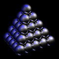 Face-centered cubic molecular crystal arrangement; one of two most-compact arrangements known.
 -
 Originally to show molecular crystal structure. The gold balls highlight the distinction to hexagonal.
 -
 Another molecular arrangement known as “hexagonal”. Used on Close-packing of spheres.
 -
 An example of ray tracing. Used on Ray tracing (graphics).
 -
 Wrist-worn heart rate monitor for Sports Instruments.
 -
 Shower head concept.
 -
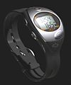 Sport watch for Sports Instruments.
 -
 Liquid measuring cup for COPCO.
 -
 Geometry in solid modeling is fully described in 3‑D space; objects can be viewed from any angle.
 -
 Analytic surface of a nozzle being edited with the Drafting Assistant


.jpg)
.jpg)


See also
- Comparison of CAD editors for architecture, engineering and construction (AEC) (comparative list of other CAD programs)
- 3D computer graphics software (with a list of other major CAD programs)
- Comparison of 3D computer graphics software
- 3D computer graphics
- 3D modeling
- Solid modeling
- Computer-aided design
- Freeform surface modelling
- Geometric dimensioning and tolerancing
- Ray tracing
Notes
- ^ Martin Newell created the Utah teapot in 1975 and went on to work at Xerox PARC, where the graphical user interface (windows, mouse, menus) was invented.
References
- ^ a b Ashlar-Vellum: Cobalt™ Feature List
- ^ a b MCADVision, “Blend of 2D and 3D Solid Modeling Speeds Design of New Heart Rate Monitor Watch”, Aug. 5, 2002, by Luc Heiligenstein of Tres Design Group
- ^ Mechanical Design / MCADonline, “Ashlar Vellum Cobalt 7.0,” by Al Dean
- ^ Ashlar-Vellum’s overview: Organic Workflow
- ^ Patent No. 5,123,087 (fetch from USPTO), and 5,371,845 (fetch from USPTO)
- ^ Ashlar-Vellum’s overview: The Drafting Assistant™
- ^ Ashlar-Vellum: Product Overview (product-family comparison chart)
External links
- Ashlar-Vellum: Cobalt™ (product overview)
- Dean, Al (March 21, 2006) Ashlar Vellum Cobalt 7.0, MCAD Online review
- George, Donna Pellerin (March 1, 2003) Solid/surface modeling, CADalyst