
Storage tank
A tank is a construction or a container, usually for holding liquids, sometimes for gases. The term can be used for both reservoirs (artificial lakes and ponds), and for manufactured containers. The usage of the word tank for reservoirs is common or universal in Indian English, and moderately common in British English. In other countries, the term tends to refer only to artificial containers.
Reservoirs can be covered, in which case they may be called covered or underground storage tanks or reservoirs. Covered water tanks are common in urban areas.
Container tanks can be many shapes, but large tanks tend to be cylindrical, or to have rounded corners, to easier withstand hydraulic pressure of contained liquid.
A large tank is sometimes mounted on a lorry or on an articulated lorry trailer, which is then called a tanker.
General Specification For Storage Tanks
1. GENERAL
1.1. This general specification covers the minimum requirements for the design, materials fabrication, inspection and testing of storage Tank.
1.2. This specification shall be read together with the General Supply Rules for welding and NDE for Storage Tanks.
1.3. This engineering specification shall be used together with: API standard 650, TENTH EDITION, NOVEMBER 1998 and addendum 1. Jan 2000 & Add.2 Nov.2001
1.4. Requirements specified herein are additions to API 650 unless specifically noted as an exception.
1.5. DEFINITIONS For the purpose of this specification, the following definitions shall apply CONTRACTOR: Party which carries out all or part of the design, engineering.
MANUFACTURER/SUPPLIER: Party which manufactures or supplies equipment and services to perform the duties specified by the Owner.
1.6. APPLICABLE SPECIFICATIONS AND CODES
1.6.1. Specifications And Codes • API standard 650 Welded Steel tanks for oil Storage
(1998 Edition + Addenda 2000)
• API standard 2000 Venting atmospheric and low pressure storage
(Fifth Edition; Errata-November 15, 1999) tanks
• ASME Section V Non-destructive Examination
(1998 Edition + 2000 Addenda)
• ASME Section IX Welding and Brazing Qualification
(1998 Edition + 2000 Addenda)
• ASME B 16.5 Pipe flanges and flanged fittings
(1996 Edition + 1998 Addenda)
• ASTM Standards Specifications for materials
(2000 Edition)
• ASME B 16.47 Series B flanges Large Diameter steel flanges NPS 26 through
(1996 Edition) NPS 60
• API RP 2003 Protection Against Ignitions Arising out of static, lightning and stray currents • ASME B 16.20 Metallic gaskets for piping
(1998 Edition + 2000 Addenda)
• ASME B 16.20 Metallic gaskets for piping
(1998 Edition + 2000 Addenda)
• ASME B 16.21 Nonmetallic flat gaskets for pipe flange
(1992 Edition)
• UBC Uniform building code, for wind and (1997 Edition) earthquake design • AWS American Welding Society for joint Specifications and welding electrodes
1.6.2. System Of Units SI metric System. 1.7. DOCUMENTS PRIORITY In case of conflict between documents listed below, the ones appearing earlier in the list shall take precedence over those appearing later: Governmental/local legislation/regulations/standards. Data sheets/drawings. This specification Other specifications codes and standards referred ot in the above documents. Any conflict between the above documents must be brought to CONTRACTOR's attention and written clarification obtained before proceeding with manufacturing or any other work.
2. DESIGN Paragraph numbers below refer to those of API 650.
2.1. The material shall comply with relevant certificates per EN 10204 3.1.B for the following parts: Shell, roof, bottom plates and nozzles All elements directly welded to the tanks All alloy and non ferrous materials For other remaining parts certificate 2.2 is required.
2.2. No material modifications are allowed after order award.
2.2.1. As a general rule, all the selected materials shall comply with the specifications of the contractual documents. During the proposal stage the Supplier may however propose alternate materials if economically and/or technically convenient in Supplier's experience. In all cases their use is subject to Contractor's and Owner's written approval.
2.3. PLATES
2.3.1. Annular plate material shall be of the same material group per API STD 650 as the lowest shell course.
2.3.2. Rimmed and capped steels shall not be used for shell, bottom and roof plates.
2.3.3. Heat Treatments Of Plate When post weld heat treatment is foreseen, the mechanical tests shall be performed on test specimens subjected to a previous heat treatment like the final one regards heating rate, holding time and cooling rate.
2.4. BOLTING (Exception) Flange bolting material shall conform to A193 Grade B7 bolts with A194 Grade 2H nuts.
2.5. JOINTS
2.5.1. Typical Joints
2.5.1.1. All bottom plates shall be lap-welded joints with a minimum of 25mm overlap.
2.5.1.2. Cone roof lap joints shall have a minimum of 25mm overlap.
2.6. BOTTOM PLATES
2.6.1. The tank bottom shall be sloped in accordance with the Tank Data Sheet. 2.7. SHELL OPENING
2.7.1. The minimum size of nozzle for equipment shall be 1” ½ inch.
2.7.2. Shell Nozzles and Flanges
2.7.2.1. Minimum distance from bottom of tank to center of nozzle shall be in accordance with API Low Type, unless otherwise specified. Generally, the minimum elevation ot the nozzle shall be such as to meet the requirement of clause
2.7.3. Of API650. Use of low type nozzles shall be restricted to drain nozzles only.
2.8. SHELL ATTACHMENT AND TANK APPURTENANCES
2.8.1. All open vents shall be protected by bird screens.
2.8.2. The minimum size of nozzle for equipment shall be 1” ½ inch. The minimum size of roof manhole shall be 24”
2.8.3. Platforms, Walkways, and Stairways
2.9. TOP AND INTERMEDIATE WIND GIRDERS
2.9.1. Intermediate Wind Girders
2.9.1.1. The minimum required thickness for the design condition, excluding corrosion allowance, shall be used to calculate the maximum height of unstiffened shell.
2.10. ROOFS
2.10.1. The type of roof shall be as specified on the Tank Data or guide drawing.
2.10.1.1. All fixed roof tanks in hydrocarbon service shall be checked for the frangibility of roof to shell joint. If not frangible, emergency venting device as per API 2000 shall be provided.
2.10.1.2. When an internal coating is specified for a fixed roof, a self-supported roof shall be used, and the roof lap joints shall be continuously welded on both sides. The roof supports (if any) shall be placed outside the roof.
2.11. Heating coil pipes, if provided shall be of seamless quality
2.12. Hand railing shall be provided all around the roof for all fixed roof Tanks.
3. FABRICATION Paragraph numbers below refer to those of API 650.
3.1. WORKMANSHIP The profile of all shell plates shall be accurate within tolerance of 2 mm in length and ±1 mm in width. In addition, to ensure that plates are truly rectangular, the length of the two diagonals measured across the rectangle from each edge shall not differ by more that 3mm. All flange bolt holes shall straddle the axial centerline of the tank.
3.2. FINISH OF PLATE EDGES In addition to the code requirements, the bevels of plates shall be visually inspected. Damaged areas, if any, shall be repaired using the approved WPS. Inspection shall be repeated after the repair.
3.3. SHAPING OF SHELL PLATES
3.3.1. Reinforcing pads and all other external attachment pads shall have rounded corners of minimum 50mm radius. All reinforcing pads shall be provided with a 6mm telltale hole.
3.3.2. All shell plates shall be rolled to suit the curvature of the tank and bevelled.
3.3.3. Marking Each piece shall be clearly marked up with reference to construction drawings and packing list.
3.4. SHIPPING All flange faces and other machined surfaces shall be greased and properly protected for shipping. The plate bevels also shall be protected for shipping.
3.4.1. (Exception) The Tank Manufacturer shall check to ensure that the dimensional tolerances of the tank foundation are satisfactory prior to start of erection.
3.4.2. The bottom side of the bottom plates shall be cleaned of all foreign matter and brush-blast cleaned prior to being placed in position for welding. The inside surfaces of bottom plates that are not internally coated shall also be brush-blast cleaned prior to welding.
3.5. DETAILS OF WELDING
3.5.1. (Exception) If not otherwise agreed the plates shall be fixed before welding by suitable dogs, clamps etc.
3.5.2. Tack welding shall be avoided as far as possible.
3.5.3. Welding procedure specifications and welder’s qualification for the tank shall be submitted to CONTRACTOR prior to the start of field erection.
3.5.4. All structural attachment welds to the tank shell, bottom, roof, and appurtenances shall be continuously seal welded.
3.5.5. All welds shall be free from coarse ripples, undercuts outside the applicable code limits, grooves, overlaps, abrupt ridges and valleys to avoid stress concentration points and interference with interpretation of NDT results.
3.5.6. All temporary or auxiliary welds (dogs, support, etc.) shall be performed with WPS used for the main seams.
3.5.7. The temporary supports shall be cold-removed by grinding; arc-air may be otherwise used with a duly protection of the base material.
3.6. BOTTOMS
3.6.1. Weld crowns of the bottom annular plate joints shall be ground flush at the contact areas with the first shell course.
4. EXPEDITING, INSPECTION, TESTING AND REPAIRS Paragraph numbers below refer to those of API 650.
4.1. Prior to final inspection and pressure testing, the inside and outside of the tank shall be thoroughly cleaned of all slag, scale, dirt, grit, weld spatter, paint, oil, etc.
4.2. Inspection of Tank Bottom Welds (Exception) All bottom joints shall be tested by using the vacuum box method before any surface coating is applied.
4.3. The initial weld pass of inner fillet weld of the shell-to-bottom joint shall be tested for leaks prior to welding the outside fillet welds. The test shall be performed by spraying with penetrating oil outside the tank and checking for leaks from the inside. The penetrating oil shall be completely removed before welding the outside weld.
4.4. The inside fillet welds of the shell-to-bottom weld joint shall be examined by either the dye penetrant or magnetic particle method before and after the hydrostatic test.
4.5. TESTING OF THE SHELL Tanks shall be hydrostatically tested in accordance with API STD 650 for a minimum period of 24 hours. However a hydraulic test procedure.
4.6. The Tank Manufacturer shall furnish all test materials and facilities, including blinds, bolting, and gaskets.
4.7. The tank shall be completely drained and thoroughly dried immediately after completion of the hydrostatic test.
4.8. Magnetic particle or liquid penetrant examination shall be conducted on all structural attachment welds to tank shells that are made after the hydrostatic test. Structural steel should be welded before hydrostatic test.
4.9. TESTING OF THE ROOF
4.9.1. Prior to the roof installation, fixed roof column supports shall be inspected for plumbness and tank shells shall be inspected for distortion or ovalization. Roof support columns which are out-of-plumb by more than 12mm in every 3m and/or more than 50mm for the total length, shall be realigned.
4.10. TANK SETTLEMENT MEASUREMENTS (This paragraph is totally added to API 650)
4.10.1. For tanks 15m diameter and larger, the base elevation shall be established and recorded at equidistant locations around the tank circumference in multiples of four, but not to exceed 10m between each reference point. The measurement points shall be at well marked locations on the annular plate or on clips welded to the shell. Elevation readings shall be taken as follows: 1. Before hydrostatic testing has started 2. At the 1/2 filled point 3. At the 3/4 filled point 4. At the maximum water fill height 5. After the tank has been emptied of test water.
4.10.2. Any differential settlement greater than 1.5mm per meter of circumference, or a uniform settlement in excess of 50mm, shall be reviewed by the CONTRACTOR. Filling shall be stopped until clearance to continue has been received from the CONTRACTOR.
4.10.3. For tanks 15m diameter and larger, internal bottom elevation measurements shall be made before and after the hydrostatic test. These measurements shall be made at 3m intervals along diametric lines across the bottom. The diametric lines shall be spaced approximately 10m apart at the tank shell. 4.11. RADIOGRAPHIC METHOD
4.11.1. Determination of Limits of Defective Welding The additional spots to be radiographed shall be specified by the CONTRACTOR.
4.11.2. a/b (Exception) Welded joints shall be acceptable with the following requirements, as a minimum: Cracks: not acceptable Undercuts: only minor depth (0.5 mm) is acceptable Overlaps: to be removed by grinding Lack of penetration: not acceptable Arc strikes: not allowed Spatters: to be removed Surfaces: major weld bed irregularity shall be removed by grinding. provided by hosein ghazanfary (asmanhgh@yahoo.com)
Special features
Since most liquids can spill, evaporate, or seep through even the tiniest opening, special consideration must made for their safe and secure handling.
Floating roof
Some storage tanks need a floating roof in addition to or in lieu of the fixed roof and structure. This floating roof rises and falls with the liquid level inside the tank, thereby decreasing the vapor emittable area. Floating roofs are considered a safety requirement as well as a pollution prevention measure for many industries including petroleum refining.
Types of tanks
High pressure
In the case of a liquefied gas such as hydrogen or natural gas, or a compressed gas such as compressed natural gas or MAPP, the storage tank must be made to withstand the sometimes immense pressures exerted by the contents. These tanks may be called cylinders.
Milk tank
In dairy farming a bulk milk cooling tank is a large storage tank for cooling and holding milk at a cold temperature until it can be picked up by a milk hauler. The bulk milk cooling tank is an important milk farm equipment. It is usually made of stainless steel and used every day to store the raw milk on the farm in good condition. It must be cleaned after each milk collection. The milk cooling tank can be the property of the farmer or being rented to the farmer by the dairy plant.
Septic tank
A septic tank is part of a small scale sewage treatment system often referred to as a septic system,. It consists of the tank and a septic drain field. Wastewater enters the tank where solids can settle and scum floats. Anaerobic digestion occurs on the settled solids, reducing the volume of solids. The water released by the system is normally absorbed by the drain field without needing any further treatment.
Mobile "storage" tanks
While not strictly a "storage" tank, mobile tanks share many of the same features of storage tanks. Also, they must be designed to deal with a heavy sloshing load and the risk of collision or other accident. Some of these include ocean-going oil tankers and LNG carriers; railroad tank cars; and the road and highway traveling tank trucks. Also included are the holding tanks which are the tanks that store toilet waste on RVs and boats.
See also
- Ballast tank
- Irrigation tank in India. Some Indian language words similar to "tak" or "tank" mean "reservoir for water".
- BS 4994: British Standard 4994:1987 specification for design and construction of vessels and storage tanks in reinforced plastics
- Fuel tank
- Oil depot
- Pressure vessel
- Tank blanketing
- Underground storage tank
- Vacuum flask
- Water heating
Images
-
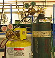 Oxygen and MAPP gas cylinders
 -
 Steel pressure vessel
 -
 Milk cooling tank
 -

-
 Septic tank
 -
 Tanker lorry
 -
Several large tanks at an airport. For scale, note concrete highway barriers.


Etymology
The word "tank" originally meant "artificial lake" and came from India, perhaps via Portuguese tanque. It may have some connection with:-
- Some Indian language words similar to "tak" or "tank" and meaning "reservoir for water".
- The Arabic verb istanqa`a = "it [i.e. some liquid] collected and became stagnant".