Patch panel


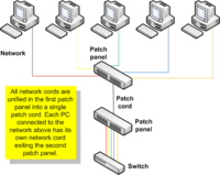
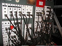
A patch panel or patch bay is a panel, typically rackmounted, that houses cable connections. One typically shorter patch cable will plug into the front side, whereas the back holds the connection of a much longer and more permanent cable. The assembly of hardware is arranged so that a number of circuits, usually of the same or similar type, appear on jacks for monitoring, interconnecting, and testing circuits in a convenient, flexible manner.
Patch panels offer the convenience of allowing technicians to quickly change the path of select signals, without the expense of dedicated switching equipment. This was first used by early telephone exchanges, where the telephone switchboard (a massive array of patch panels) and a large room full of telephone operators running it was ubiquitous.
Uses and connectors
In recording studios, television and radio broadcast studios, and concert sound reinforcement systems, patchbays are widely used to facilitate the connection of different devices, such as microphones, electric or electronic instruments, effects (e.g. compression, reverb, etc.), recording gear, amplifiers, or broadcasting equipment. Patchbays make it easier to connect different devices in different orders for different projects, because all of the changes can be made at the patchbay. As well, patchbays make it easier to troubleshoot problems such as ground loops; even small home studios and amateur project studios often use patchbays, because it groups all of the input jacks into one location. This means that devices mounted in racks or keyboard instruments can be connected without having to hunt around behind the rack or instrument with a flashlight for the right jack. Using a patchbay also saves wear and tear on the input jacks of studio gear and instruments, because all of the connections are made with the patchbay.
Normalling
It is conventional to have the top row of jacks wired at the rear to outputs and bottom row of jacks wired to inputs. Patch bays may be half-normal (usually bottom) or full-normal, "normal" indicating that the top and bottom jacks are connected together internally. When a patch bay has half-normal wiring, then with no patch cord inserted into either jack, the top jack is internally linked to the bottom jack via break contacts on the bottom jack; inserting a patch cord into the top jack will take a feed off that jack whilst retaining the internal link between the two jacks; inserting a patch cord into the bottom jack will break the internal link and replace the signal feed from the top jack with the signal carried on the patch cord. If a patch bay is wired to full-normal, then it includes break contacts in both rows of jacks.

Switches
Dedicated switching equipment can be an alternative to patch bays in some applications. Switchers can make routing as easy as pushing a button, and can provide other benefits over patch bays, including routing a signal to any number of destinations simultaneously. However, switching equipment that can emulate the capabilities of a given patch bay is much more expensive.
Example: a 16-point S-Video patch panel, with 8 patch cables, cost may start at $150.00[citation needed], and connect 8 inputs and 8 outputs. An S-Video matrix routing switcher with the same capability (8x8) would probably cost between $2,000.00 and $4,000.00 new, though it would probably have more capabilities, including audio-follow-video and built-in distribution amplifiers.
There are various types of switchers for audio and video, from simple selector switches to sophisticated production switchers. However, emulating or exceeding the capabilities of audio and/or video patch bays requires specialized devices like routing switchers and matrix routers (aka "crosspoint switchers").
Like patch panels, switching equipment for nearly any type of signal is available, including analog and digital video and audio, as well as RF (cable TV), MIDI, telephone, networking, electrical, and just about anything else.
Switching equipment may be electronic, mechanical, or electro-mechanical. Some switcher hardware can be controlled via computer and/or other external devices. Some have automated and/or pre-programmed operational capabilities. There are also software switcher applications used to route signals and control data within a "pure digital" computer environment.
Distribution frames are cheaper, but less convenient.
See also
External links
- Video Overview of a Category 5e Patch Panel and it's Uses
- Step by Step Instructions on How to Terminate Twisted Pair Cable on a Category 5e Patch Panel
References
 This article incorporates public domain material from Federal Standard 1037C. General Services Administration. Archived from the original on 2022-01-22. (in support of MIL-STD-188).
