
Suspension bridge: Difference between revisions
add link, simplify |
Leonard G. (talk | contribs) m clarify a bit |
||
| Line 14: | Line 14: | ||
}} |
}} |
||
A '''suspension bridge''' is a type of [[bridge]] in which the deck (the load-bearing portion) is hung below suspension [[cables]] on vertical suspenders. While modern bridges of this type date from the early 19th century, |
A '''suspension bridge''' is a type of [[bridge]] in which the deck (the load-bearing portion) is hung below suspension [[cables]] on vertical suspenders. While modern bridges of this type date from the early 19th century, earlier bridges without vertical suspenders ([[simple suspension bridge]]s) date from the [[7th Century]] in [[Central America]]. |
||
[[File:Puente colgante peatonal construido artesanalmente.jpg|thumb|left|Suspended-deck suspension bridge with a distinctly arched deck]] |
[[File:Puente colgante peatonal construido artesanalmente.jpg|thumb|left|Suspended-deck suspension bridge with a distinctly arched deck]] |
||
Revision as of 17:16, 31 March 2009
 An early bridge of this type, the Clifton Suspension Bridge | |
| Ancestor | Simple suspension bridge |
|---|---|
| Related | Underspanned suspension bridge; see also cable stayed bridge and compression arch suspended-deck bridge |
| Descendant | Self-anchored suspension bridge |
| Carries | Pedestrians, bicycles, livestock, automobiles, trucks, light rail |
| Span range | Medium to long |
| Material | Steel rope, multiple steel wire strand cables or forged or cast chain links |
| Movable | No |
| Design effort | medium |
| Falsework required | No |
A suspension bridge is a type of bridge in which the deck (the load-bearing portion) is hung below suspension cables on vertical suspenders. While modern bridges of this type date from the early 19th century, earlier bridges without vertical suspenders (simple suspension bridges) date from the 7th Century in Central America.

This type of bridge has cables suspended between towers, plus vertical suspender cables that carry the weight of the deck below, upon which traffic crosses. This arrangement allows the deck to be level or to arc upward for additional clearance. Like other suspension bridges, this type often is constructed without falsework.
The suspension cables must be anchored at each end of the bridge, since any load applied to the bridge is transformed into a tension in these main cables. The main cables continue beyond the pillars to deck-level supports, and further continue to connections with anchors in the ground. The roadway is supported by vertical suspender cables or rods, called hangers. In some circumstances the towers may sit on a bluff or canyon edge where the road may proceed directly to the main span, otherwise the bridge will usually have two smaller spans, running between either pair of pillars and the highway, which may be supported by suspender cables or may use a truss bridge to make this connection. In the latter case there will be very little arc in the outboard main cables.
History

The suspended-deck suspension bridge is one of the older forms of suspension bridge. Lacking a sufficiently level and stable deck, most simple suspension bridges are not suited for modern roads and railroads. Advances in materials and design led to the development of the suspended deck bridge, a modern bridge capable of carrying vehicles and light rail. In the late 7th Century, the Mayan empire had the earliest known suspended-deck suspension bridge, the Maya Bridge at Yaxchilan. Claims that suspension bridges with a horizontal deck (presumably a suspended deck) originated in Tibet or China remain largely unsubstantiated. The first design for a bridge resembling the modern suspended deck bridge in the West is attributed to Faust Vrančić, whose 1595 book “Machinae Novae” included drawings both for a timber and rope suspension bridge, and a hybrid suspension and cable-stayed bridge using iron chains. However, the first such bridge actually built was James Finley’s iron chain bridge at Jacob’s Creek, in Pennsylvania, in 1801. This was widely publicised from 1810 onwards, beginning a period of rapid development of the modern suspended-deck suspension bridge.
Early British chain bridges included the Dryburgh Abbey Bridge (1817) and 137 m Union Bridge (1820), with spans rapidly increasing to 176 m with the Menai Suspension Bridge (1826). The Clifton Suspension Bridge shown above (designed in 1831, completed in 1864 with a 214 m central span) is one of the longest of the parabolic arc chain type.
The first permanent wire cable suspension bridge was Guillaume Henri Dufour’s Saint Antoine Bridge in Geneva of 1823, with two 40 m spans.[1] The first with cables assembled in mid-air in the modern method was Joseph Chaley’s Grand Pont Suspendu in Fribourg, in 1834.[1]
Structural behavior
Structural analysis
The main forces in a suspension bridge of any type are tension in the cables and compression in the pillars. Since almost all the force on the pillars is vertically downwards and they are also stabilized by the main cables, the pillars can be made quite slender, as on the Severn Bridge, near Bristol, England.

In a suspended deck bridge, cables suspended via towers hold up the road deck. The weight is transferred by the cables to the towers, which in turn transfer the weight to the ground.
Assuming a negligible weight as compared to the weight of the deck and vehicles being supported, the main cables of a suspension bridge will form a parabola (very similar to a catenary, the form the unloaded cables take before the deck is added). One can see the shape from the constant increase of the gradient of the cable with linear (deck) distance, this increase in gradient at each connection with the deck providing a net upward support force. Combined with the relatively simple constraints placed upon the actual deck, this makes the suspended deck bridge much simpler to design and analyze than a cable-stayed bridge, where the deck is in compression.
Disadvantages compared with other bridge types
- Considerable stiffness or aerodynamic profiling may be required to prevent the bridge deck vibrating under high winds
- The relatively low deck stiffness compared to other (non-suspension) types of bridges makes it more difficult to carry heavy rail traffic where high concentrated live loads occur
- Some access below may be required during construction, to lift the initial cables or to lift deck units. This access can often be avoided in cable-stayed bridge construction
Variations
Suspension cable types


The main suspension cable in older bridges was often made from chain or linked bars, but modern bridge cables are made from multiple strands of wire. This is for greater redundancy; a few flawed strands in the hundreds used pose very little threat, whereas a single bad link or eyebar can cause failure of the entire bridge. (The failure of a single eyebar was found to be the cause of the collapse of the Silver Bridge over the Ohio river). Another reason is that as spans increased, engineers were unable to lift larger chains into position, whereas wire strand cables can be largely prepared in mid-air.
Deck structure types

Most suspended deck bridges have open truss structures to support the roadbed (particularly owing to the unfavorable effects of using plate girders, discovered from the Tacoma Narrows bridge collapse). Recent developments in bridge aerodynamics have allowed the re-introduction of plate structures. In the illustration to the right, note the very sharp entry edge and sloping undergirders in the suspension bridge shown. This enables this type of construction to be used without the danger of vortex shedding and consequent aeroelastic effects, such as those that destroyed the Tacoma Narrows Bridge.
Use other than road and rail

The principles of suspension used on the large scale may also appear in contexts less dramatic than road or rail bridges. Light cable suspension may prove less expensive and seem more elegant for a footbridge than strong girder supports. Where such a bridge spans a gap between two buildings, there is no need to construct special towers, as the buildings can anchor the cables. Cable suspension may also be augmented by the inherent stiffness of a structure that has much in common with a tubular bridge.
Construction sequence (wire strand cable type)


- Where the towers are founded on underwater piers, caissons are sunk and any soft bottom is excavated for a foundation. If the bedrock is too deep to be exposed by excavation or the sinking of a caisson, pilings are driven to the bedrock or into overlying hard soil, or a large concrete pad to distribute the weight over less resistant soil may be constructed, first preparing the surface with a bed of compacted gravel. (Such a pad footing can also accommodate the movements of an active earthquake fault, and this has been implemented on the foundations of the cable-stayed Rio-Antirio bridge. The foundation piers are then extended to above water level.
- Where the towers are founded on dry land, deep foundation excavation or pilings are used.
- From the tower foundation, towers of single or multiple columns are erected using concrete, stonework, or steel structures. At some elevation there must be a passage for the deck, with the columns extending high above this level.
- Smooth open cable paths called saddles are anchored atop the towers. These allow for slight movements of the cable as the loads change during construction. The top of these saddles may be closed with an additional part after completion of the bridge.
- Anchorages are constructed to resist the tension of the cables. These are usually anchored in good quality rock, but may consist of massive reinforced concrete deadweights within an excavation. The anchorage structure will have multiple protruding open eyebolts enclosed within a secure space.
- A temporary suspended walkway supported by wire rope follows the curve of the cables to be constructed, mathematically described as a catenary arc.
- Another set of wire ropes are suspended above the walkway and are used to support a traveler that has wheels riding atop these cables. There will be one set of wire ropes and a traveler for each cable to be “spun”.
- Pulling cables attached to winches are capable of pulling the traveler from one anchorage to the other, traveling in arcs to the tops of the two towers.
- High strength wire, typically less than 10 mm in diameter, is pulled in a loop by pulleys on the traveler, with one end affixed at an anchorage. Workers stationed along the walkway attach the passing cable to a bundle with a temporary binding. When the traveler reaches the opposite anchorage the loop is placed over an open anchor eyebar.
- The traveler is returned to the start point to pick up another loop or it is used to carry a new loop from this side.
- As loops are placed, corrosion proofing may be applied.
- In this way a complete sub-cable is created linking the eyebar (or a set of eyebars) from one anchorage to the other. The sub-cables will have a hexagonal cross section and are held together with the temporary bindings.
- Multiple adjacent sub-cables are placed adjacent to each other. While these are on a hexagonal grid, the general form for the larger cable is circular.
- The entire cable is then compressed by a traveling hydraulic press into a closely packed cylinder and tightly wrapped with additional wire to form the final circular cross section.
- Saddles to carry the suspender cables are clamped to the main cables, each with an appropriate shape to conform to the ultimate slope of the main cables. Each saddle is an equal horizontal distance from the next, with spacing appropriate to the design of the deck.
- Suspender cables engineered and cut to precise lengths and carrying swedged ends are looped over the saddles. In some bridges, where the towers are close to or on the shore, the suspender cables may be applied only to the central span.
- Special lifting hosts attached to the suspenders or from the main cables are used to lift prefabricated sections of bridge deck to the proper level, provided that the local conditions allow the sections to be carried below the bridge by barge or other means, otherwise a traveling cantilever may be used to extend the deck one section at a time. If the addition of the deck structure extends from the towers the finished portions of the deck will pitch upward rather sharply, as there is no downward force in the center of the span. Upon completion of the deck the added load will pull the main cables into an arc mathematically described as a parabola, while the arc of the deck will be as the designer intended — usually a gentle upward arc for added clearance if over a shipping channel, or flat in other cases such as a span over a canyon.
- With completion of the primary structure various details such as lighting, handrails, finish painting and paving are added.
The longest suspended-deck suspension bridge spans in the world

Suspension bridge are typically ranked by the length of their main span.
- Akashi-Kaikyo Bridge (Japan), 1991 m — 1998
- Xihoumen Bridge (China), 1650 m — 2007
- Great Belt Bridge (Denmark), 1624 m — 1998
- Runyang Bridge (China), 1490 m — 2005
- Humber Bridge (England, United Kingdom), 1410 m — 1981. (The longest span from 1981 until 1998.)
- Jiangyin Suspension Bridge (China), 1385 m — 1997
- Tsing Ma Bridge (Hong Kong, China), 1377 m — 1997 (longest span with both road and metro)
- Verrazano Narrows Bridge (USA), 1298 m — 1964. (The longest span from 1964 until 1981.)
- Golden Gate Bridge (USA), 1280 m — 1937. (The longest span from 1937 until 1964.)
- Yangluo Bridge (China), 1280 m — 2007
Other suspended-deck suspension bridges
- Brooklyn Bridge (USA, 1883), The first steel-wire suspension bridge.
- Bear Mountain Bridge (USA, 1924), The longest span (497 m)from 1924 to 1926. The first suspension bridge to have a concrete deck. The construction methods pioneered in building it would make possible several much larger projects to follow.
- Mackinac Bridge (USA, 1957), The longest suspension bridge between anchorages in the Western hemisphere.
- Royal Gorge Bridge (USA, 1929), The highest (384 m) suspension bridge in the world.
- San Francisco – Oakland Bay Bridge (USA, 1936), Until recently, this was the longest steel high-level bridge in the world (704 m).[2] The eastern portion (a cantilever bridge) is being replaced with a self-anchored suspension bridge which will be the longest of its type in the world.
- Tacoma Narrows Bridge (USA, 1950 & 2007), The largest twin suspension bridge in the world (853 m).
- Union Bridge (England/Scotland, 1820), The longest span (137 m) from 1820 to 1826. The oldest in the world still in use today.
Infamous suspended-deck suspension bridges
- The Bridge of San Luis Rey (Fictional)
- Silver Bridge, a 1928 eyebar chain bridge that collapsed in 1967, killing forty-six people.
- Tacoma Narrows Bridge, (USA), 853 m — 1940. The Tacoma Narrows was structurally vulnerable to sustained and moderately strong winds. This was due to a phenomenon called aeroelastic fluttering (owing to its unique plate-girder deck structure and ultimately its nickname “The Galloping Gertie”). This led to its collapse only months after completion. The collapse was captured on film.
Picture Gallery
-
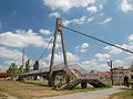 Suspension bridge without river in Zrenjanin, Serbia
 -
 Akashi-Kaikyo Bridge at night
 -
 25 de Abril Bridge in Lisbon, Portugal
 -
 A suspension bridge falls: Tacoma Narrows Bridge collapses
 -
 The Ambassador Bridge — Longest suspension bridge from 1929–1931.
 -
 New York’s Brooklyn Bridge
 -
 San Francisco – Oakland Bay Bridge under construction
 -
 Driving on the 2nd largest suspension bridge, Denmark’s Great Belt Bridge (Storebæltsbroen).
 -
Busan, the Republic of Korea’s Gwangan Grand Bridge, with a suspension section of around 500 meters but with an overall length of 7,420 meters
-
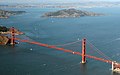 The Golden Gate Bridge in San Francisco
 -
 Ortaköy Mosque and the Bosphorus Bridge in Istanbul
 -
 Brooklyn Bridge with Manhattan Bridge in background
 -
 Western portion of the San Francisco – Oakland Bay Bridge — two bridges with a common central anchorage
 -
 Golden Gate Bridge, California, USA
 -
 Mackinac Bridge in a snowstorm, during high winds, the bridge has to be closed.
 -
 The Mackinac Bridge at night.
 -
 Suspension Bridge in Ozolnieki, Latvia.
 -


See also
- Category:Suspended deck bridges — for articles about specific suspended deck bridges.
- List of longest suspension bridge spans
- Timeline of three longest spans whether bridge, aerial tramway, powerline, ceiling or dome etc.
- Cable-stayed bridge — superficially similar to a suspension bridge, but cables from the towers directly support the roadway, rather than the road being suspended indirectly by additional cables from the main cables connecting two towers.
- Inca rope bridge — has features in common with a suspension bridge and predates them by at least three hundred years. However in a rope bridge the deck itself is suspended from the anchored piers and the guardrails are non-structural.
- Self-supporting suspension bridge — combining elements of a suspension bridge and a cable-stayed bridge.
- Simple suspension bridge — a modern implementation of the rope bridge using steel cables, although either the upper guardrail or lower footboard cables may be the main structural cables.
References
- ^ a b Tom F. Peters (1987). Transitions in Engineering: [[Guillaume Henri Dufour]] and the Early 19th Century Cable Suspension Bridges. Birkhauser. ISBN 3764319291.
{{cite book}}: URL–wikilink conflict (help) - ^ McGloin, Bernard. "Symphonies in Steel: Bay Bridge and the Golden Gate". Virtual Museum of the City of San Francisco. Retrieved 2008-01-12.
External links
- New Brunswick Canada suspension footbridges
- Structurae: suspension bridges
- American Society of Civil Engineers History and heritage of civil engineering — bridges
- Bridgemeister: Mostly suspension bridges
- Wilford, John Noble (May 8, 2007). Inca suspension bridges "How the Inca Leapt Canyons". The New York Times.
{{cite web}}: Check|url=value (help)
| Structural types |
|  |
|---|---|---|
| Lists of bridges by type | ||
| Lists of bridges by size | ||
| Additional lists | ||
| Related | ||