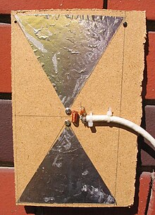
Biconical antenna
This article needs additional citations for verification. (November 2011) |

In radio systems, a biconical antenna is a broad-bandwidth antenna made of two roughly conical conductive objects, nearly touching at their points.[1]
Biconical antennas are broadband dipole antennas, typically exhibiting a bandwidth of three octaves or more. A common subtype is the bowtie antenna, essentially a two-dimensional version of the biconial design which is often used for short-range UHF television reception. These are also sometimes referred to as butterfly antennas.

Properties
The biconical antenna has a broad bandwidth because it is an example of a traveling wave structure; the analysis for a theoretical infinite antenna resembles that of a transmission line. For an infinite antenna, the characteristic impedance at the point of connection is a function of the cone angle only and is independent of the frequency.
Practical antennas have finite length and a definite resonant frequency.[1] A simple conical monopole antenna is a wire approximation of the solid biconical antenna and has increased bandwidth (over a simple monopole).
Applications

Biconical (or "bicon") antennas are often used in electromagnetic interference (EMI) testing either for immunity testing, or emissions testing.
Advantages and drawbacks
While the bicon is very broadband, it exhibits poor transmitting efficiency at frequencies at the low end of its range, resulting in low field strengths when compared to the input power. Log periodic dipole arrays, Yagi-Uda antennas, and reverberation chambers have shown to achieve much higher field strengths for the power input than a simple biconical antenna in an anechoic chamber.
However, when the goal is to fully characterize a modulated or impulse signal, rather than merely measuring peak and average spectrum energy content, a reverberation chamber is a poor choice for a test environment.

See also
- Discone antenna
- Antenna
- Radio
- Television
- Electromagnetic reverberation chamber
- Electromagnetic compatibility
- Bicone
- Double cone
References
- ^ a b Zhuohui Zhang,Analysis and design of a broadband antenna for software defined radio, ProQuest, 2007 ISBN 0-549-46376-3, page 6
