
Talk:Lift-to-drag ratio
| This article is of interest to the following WikiProjects: | |||||||||||||||||||||||||||||||||||||||||||||||||
| |||||||||||||||||||||||||||||||||||||||||||||||||
.jpg)

Untitled
Isn't "In zero wind conditions, L/D will equal altitude lost divided by distance traveled" backwards?
The article says that maximum range is at minimum drag???
Shouldn't this be minimum drag per unit distance?WolfKeeper 16:53, 24 August 2007 (UTC)
induced drag, total drag
The explanation for induced drag in the article is wrong: lift is not defined as the force perpendicular to the wing (whatever reference line), but perpendicular to the free stream direction. Thus, induced drag cannot be explained as a consequence of the wing flying at an AOA, tilting the lift backwards. Actually, induced drag is zero for a two-dimensional wing or wing of infinite span. Induced drag is the result of the additional downwash induced by the tip vortices. This causes the wing to see a different averaged free stream which is angled downward. Furthermore, best L/D occurs at minimum drag since this drag graph is calculated for constant lift (i.e. level flight). So it is wrong to say that at slower speed there is less lift.— Preceding unsigned comment added by JaRaMW (talk • contribs) 07:49, 31 May 2011 (UTC)
- Thanks for those valid observations. I have made some changes. See the diff. Dolphin (t) 12:11, 31 May 2011 (UTC)
Supersonic/hypersonic lift to drag ratios
It's right that these drop in supersonic flight; it is the result of wave drag due to lift, absent when compressibility is not an issue. But I don't think the comparison of two different aircraft travelling at subsonic and supersonic speeds is helpful. In addition, the aerodynamics of a delta wing, even at low speeds is very different from straight or swept ones, as there are vortices not just at the tips but all along the leading edge. Much better if we can get data for one aircraft, perhaps ideally with straight wings, in the two regimes. There is a plot of CD,0 for the T-38 at 0.2 < M < 1.4 in Anderson's Aircraft Performance and Design (it increases by a factor of about 3) but no CL. Must be out there somewhere!TSRL (talk) 19:24, 27 October 2011 (UTC)
- The same book, page 136, also has drag polars at several Mach numbers for the F-15. These are not ideally presented for extracting the maximum L/D but I get about 10.3 at M=0.2 and 4.3 at M=1.4, the difference being almost entirely due to the increase in CD.TSRL (talk) 19:14, 28 October 2011 (UTC)
Wind tunnel
The lede contains a statement that Lift-to-drag ratios are usually found using a wind tunnel. The cited source is NASA. This statement is also found in Flight. Its validity is presently under discussion at Talk:Flight#Lift-to-drag ratio. Dolphin (t) 08:02, 11 May 2012 (UTC)
- User:Writ Keeper has provided a Third Opinion on this matter. See Talk:Flight#Lift-to-drag ratio. I have altered the sentence so it now states: "Lift-to-drag ratios can be determined by flight test, by calculation or by testing in a wind tunnel." We must now turn our attention to provide ini-line citations that genuinely support this statement. To ensure we don't overlook it I have added "Fact" tag immediately after the sentence. Dolphin (t) 04:07, 15 May 2012 (UTC)
How do we edit the templates used in the Examples section
eg. {{glide ratio examples}} - Rod57 (talk) 02:21, 7 December 2014 (UTC)
L/D for the Cessna 150?
A quick calculation shows the value of 7 for the C150 in cruise is too low, by at least 30 percent. No source is given. Can someone improve this entry? Thanks in advance.--Spray787 (talk) 01:36, 4 June 2015 (UTC)
Why called polar?
It is not polar coordinates, so why is it called a polar plot? 2600:1700:4CA1:3C80:2536:CFC6:40D7:3026 (talk) 23:02, 22 August 2020 (UTC)
- At Drag polar#The drag polar you will find the following explanation: "If, in a wind tunnel or whirling arm system an aerodynamic surface is held at a fixed angle of attack and both the magnitude and direction of the resulting force measured, they can be plotted using polar coordinates. When this measurement is repeated at different angles of attack the drag polar is obtained. Lift and drag data was gathered in this way in the 1880s by Otto Lilienthal and around 1910 by Gustav Eiffel, though not presented in terms of the more recent coefficients. Eiffel was the first to use the name drag polar." Dolphin (t) 08:36, 23 August 2020 (UTC)
What can we say about the L/D for flat rectangular plates
I was looking for the L/D for flat rectangular plates at various AoA, but nothing here or at Lift (force). - Rod57 (talk) 11:22, 9 December 2020 (UTC)
- Fig 5 of Effects of aspect ratio and inclination angle on aerodynamic loads of a flat plate Shaderman et al. has Cd & Cl plots for AoA > 30 degrees, and the L/D at 30 degrees inclination seems to be about 1.5. - Rod57 (talk) 11:39, 9 December 2020 (UTC)
- Maximum Lift/Drag Ratio of Flat Plates with Bluntness and Skin Friction at Hypersonic Speeds has formula for hypersonic plates - Rod57 (talk) 12:19, 9 December 2020 (UTC)
- Flat plate lift (and LDR) can be bimodal as a function of inclination eg as in fig 10 of [1] - Rod57 (talk) 12:29, 9 December 2020 (UTC)
Marc: again and again: give reasons why pics showing airspeed and angle should be given in this intro
- Your pics obviously do NOT show the topic.
- Clearly: The text is scientific NONSENSE: Clearly wrong!
- YOU refused to give any reasons.
- Therefore you do not understand WP:BRD and are lying and insulting: i gave detailed comments.
95.91.246.145 (talk) 05:31, 2 January 2022 (UTC)
- Please focus on the content of the article, and on how you believe it can be improved. A clear explanation of the source of your disagreement (e.g. what specifically makes it "scientific nonsense" in your eyes) would be helpful. Thank you. --Ariadacapo (talk) 09:25, 2 January 2022 (UTC)
@Ariadacapo: It would show respect and be helpful, if you have read my edits and comments, best have some knowledge about aviation and L/D ratio. And please focus on the content of the article! And i do not like the prejudicing, that an IP-editor has to prove his "believes", whereas an registered editor can publish unproven nonsense:
A: "The angle of the tether displays the dramatic improvement of the lift-to-drag ratio."
Prove it! ANSWER!
B: The schematic pic below shows OBVIOUSLY aerodynamic force, nothing with L/D ratio
See my comments:
- Nice picture, but has nothing to do with L/D ratio. Its angle of attack. I am moving the pic + searching for a better pic.
- Clearly wrong, Marc: merry Christmas, but read your pilot-exams: angle-of-attack is NOT L/D ratio
- you are no scientist, even for a pilot not educated, embaressing. The angle of the tether is NOT L/D ratio. Ever thought of different airspeeds? Use talk!
- rv: again: your WRONG pic shows airspeed and angle
- rv: again and again: give reasons why a pic showing airspeed and angle should be given in this intro
- rv: again and again: give reasons why a pic showing airspeed and angle should be given in this intro
- rv: again and again: give reasons why a pic showing airspeed and angle should be given in this intro
- rv: again and again: give reasons why a pic showing airspeed and angle should be given in this intro
Ever flown a kite? Airspeed and angle-of-attack are other articles, different! Angle of tether has even less to do with this topic. QED
Show respect, that means read and try to understand before giving advice! 95.91.246.145 (talk) 12:24, 2 January 2022 (UTC)
The wright pic was illustrating the article since a long time. It shows the total aerodynamic force direction, through the tether. The total aerodynamic force is subdivised in lift and drag, as explained in the schematic. The angle of the aero. force shows the relation between both components, and the improved angle shows the gain in L/D ratio. It's a good illustration:
-
 wright glider
 -
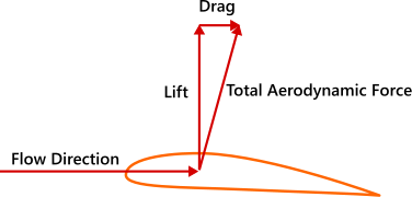 aero. force schematic


The picture is about aerodynamic force, not AoA. The tether shows the relation between two vectors through its angle. It does not shows the AoA.--Marc Lacoste (talk) 12:37, 2 January 2022 (UTC)
- The different airspeeds are giving different forces, even with the same kite. No dramatic improvement, just the same kite.
- And of course can a different angle of attack be seen. 95.91.246.145 (talk) 12:59, 2 January 2022 (UTC)