
Proximity fuze
This article needs additional citations for verification. (July 2008) |

A proximity fuze is a fuze that detonates an explosive device automatically when the distance to the target becomes smaller than a predetermined value. Proximity fuzes are designed for targets such as planes, missiles, ships at sea and ground forces. They provide a more sophisticated trigger mechanism than the common contact fuze or timed fuze.
British Army researchers Sir Samuel Curran and W. A. S. Butement developed a proximity fuze in the early stages of World War II under the name VT, an acronym of "Variable Time fuze".[1] The system was a small, short range, Doppler radar that used a clever circuit. However, the UK lacked the capacity to develop the fuze, so the design was shown to the US during the Tizard Mission in late 1940. The circuitry needed to be miniaturized, the fuze had to survive the high acceleration of cannon launch, and it needed to be reliable.[2] Development was completed under the direction of physicist Merle A. Tuve at The Johns Hopkins University Applied Physics Lab (APL).[3]
The proximity fuze is considered one of the most important technological innovations of the war. It was so important that it was a secret guarded to a similar level as the atom bomb project or D-Day invasion. It was also fiendishly tricky to manufacture.[4][5][6][7] Adm. Lewis L. Strauss wrote that, "One of the most original and effective military developments in World War II was the proximity, or "VT," fuse. It was of incalculable value to both the Army and Navy, and it helped save London from obliteration. While no one invention won the war, the proximity fuse must be listed among the very small group of developments, such as radar, upon which victory very largely depended."[8] The fuse was later found to be equally useful causing artillery shells to explode in air bursts, greatly increasing their anti-personnel effects.[9]
The Germans were supposedly also working on proximity fuses in the 1930s, based on capacitive effects rather than radar. Research and prototype work at Rheinmetall were halted in 1940 to devote available resources to projects deemed more necessary. In the post-WWII era, a number of new proximity fuse systems were developed, including radio, optical and other means. A common form used in modern air-to-air weapons uses a laser as an optical source and time-of-flight for ranging.
History
Before the proximity fuze's invention, detonation was induced by direct contact, a timer set at launch, or an altimeter. All of these earlier methods have disadvantages. The probability of a direct hit on a small moving target is low; a shell that just misses the target will not explode. A time- or height-triggered fuze requires an accurate prediction; if the setting is wrong, then even accurately aimed shells may explode harmlessly before reaching the target. With a proximity fuze, the shell or missile need only pass close by the target at some time during its trajectory. The proximity fuze makes the problem simpler than the previous methods.
Proximity fuzes are also useful for producing air bursts against ground targets. A contact fuze would explode when it hit the ground; it would not be very effective at scattering shrapnel. A timer fuze can be set to explode a few meters above the ground, but the timing is critical and usually requires observers to provide information for adjusting the timing. Observers may not be practical in many situations, the ground may be uneven, and the practice is slow in any event. Proximity fuzes fitted to such weapons as artillery and mortar shells solve this problem by having a range of pre-set burst heights (e.g. 2, 4 or 10 metres, or about 7, 13, or 33 feet) above ground that are selected by gun crews prior to firing. The shell bursts at the appropriate height above ground.
World War II
Design
In the late 1930s the UK was working on a variety of developments to increase air defence efficiency
...Into this stepped W. A. S. Butement, designer of radar sets CD/CHL and GL, with a proposal on 30 October 1939 for two kinds of radio fuze: (1) a radar set would track the projectile, and the operator would transmit a signal to a radio receiver in the fuze when the range, the difficult quantity for the gunners to determine, was the same as that of the target and (2) a fuze would emit high-frequency radio waves that would interact with the target and produce, as a consequence of the high relative speed of target and projectile, a Doppler-frequency signal sensed in the oscillator.[10]
Coincidentally, a German neon lamp tube and a design of a prototype proximity fuze based on capacitive effects was received by British Intelligence in mid November 1939. Butement, Edward S. Shire, and Amherst F.H. Thompson[1] proposed the radio frequency proximity fuze concept in a memo to the British Air Defence Establishment in May 1940. A breadboard circuit was constructed by the inventors and the concept was tested in the laboratory by moving a sheet of tin at various distances. Early field testing connected the circuit to a thyratron trigger operating a tower-mounted camera which photographed passing aircraft to determine distance of fuze function. Prototype fuzes were then constructed in June 1940, and installed in unrotated projectiles (the British cover name for solid fuelled rockets) fired at targets supported by balloons.[1] During 1940-42 a private venture initiative by Pye Ltd., a leading British wireless manufacturer, worked on the development of a radio proximity fuze. Pye's research was transferred to the United States as part of the technology package delivered by the Tizard Mission when the United States entered the war.[11] It is unclear how this work relates to other British developments. The details of these experiments were passed to the United States Naval Research Laboratory and National Defense Research Committee (NDRC) by the Tizard Mission in September 1940, in accordance with an informal agreement between Winston Churchill and Franklin D. Roosevelt to exchange scientific information of potential military value.[1]
Following receipt of details from the British, the experiments were successfully duplicated by Richard B. Roberts, Henry H. Porter, and Robert B. Brode under the direction of NDRC section T chairman Merle Tuve.[1] Lloyd Berkner of Tuve's staff devised an improved fuze using separate tubes (British English: thermionic valves or just "valves") for transmission and reception. In December 1940, Tuve invited Harry Diamond and Wilbur S. Hinman, Jr, of the United States National Bureau of Standards (NBS) to investigate Berkner's improved fuze.[1] The NBS team built six fuzes which were placed in air-dropped bombs and successfully tested over water on 6 May 1941.[1]
While working for a defense contractor in the mid-1940s, Soviet spy Julius Rosenberg stole a working model of an American proximity fuze and delivered it to the KGB.[12]
Parallel NDRC work focused on fuzes for use with anti-aircraft artillery. Major problems included microphonic difficulties and tube failures attributed to vibration and acceleration in gun projectiles. The T-3 fuze had a 52% success against a water target when tested in January, 1942. The United States Navy accepted that failure rate, and batteries aboard cruiser USS Cleveland (CL-55) tested proximity-fuzed ammunition against drone aircraft targets over Chesapeake Bay in August 1942. The tests were so successful that all target drones were destroyed before testing was complete.[1]
The German proximity fuze was developed in Rheinmetall Borsig AG. The program was halted in 1940, restarted in early 1944 and then terminated again when the factories were overrun by the Allies. The German fuze had the following characteristics:[13]
- The fuze was based on electrostatic principles. The nose of the shell was electrically insulated and isolated from the rest of the shell.
- Initial fuze testing demonstrated a sensitivity of 1–2 meters and a reliability of 80% when fired against a metal cable target. A circuit adjustment yielded an increase to 3–4 meters and a reliability of close to 95%. Further work showed a 10-15 meter sensitivity. This was with 88 mm cannon shells.
- The shell was for all intents and purposes ready for production.[citation needed] The shell probably could not have been easily degraded by jamming or chaff, unlike the Allied shell.[citation needed]
VT
The Allied fuze used constructive and destructive interference to detect its target.[14] The design had four tubes.[15] One tube was an oscillator connected to an antenna; it functioned as both a transmitter and an autodyne detector (receiver). When the target was far away, it would reflect little of the oscillator's energy back to the fuze and have almost no effect on the circuit. When a target was nearby, it would reflect a significant portion of the oscillator's signal back to the fuze. The amplitude of the reflected signal indicates the closeness of the target.[16] This reflected signal would affect the oscillator depending on the round trip distance from the fuze to the target. If the reflected signal were in phase, the oscillator amplitude would increase and the oscillator's plate current would also increase. If the reflected signal were out of phase, then the plate current would decrease.
The distance between the fuze and the target is not constant but rather constantly changing due to the high speed of the fuze and any motion of the target. When the distance between the fuze and the target changes rapidly, then the phase relationship also changes rapidly. The signals are in-phase one instant and out-of-phase a few hundred microseconds later. The result is a heterodyne beat frequency that indicates the velocity difference. Viewed another way, the received signal frequency is doppler shifted from the oscillator frequency by the relative motion of the fuze and target. Consequently, a low frequency signal corresponding to the frequency difference develops at the oscillator's plate terminal. Two additional amplifiers detected and filtered this low frequency signal. If the amplified beat frequency signal is large enough (indicating a nearby object), then it triggers the 4th tube (a gas-filled thyratron); the thyratron conducts a large current that sets off the electrical detonator. There were many shock hardening techniques including planar electrodes and packing the components in wax and oil to equalize the stresses.
Production
First large scale production of tubes for the new fuzes[1] was at a General Electric plant in Cleveland, Ohio formerly used for manufacture of Christmas-tree lamps. Fuze assembly was completed at General Electric plants in Schenectady, New York and Bridgeport, Connecticut.[17]
By 1944 a large proportion of the American electronics industry concentrated on making the fuzes. Procurement contracts increased from $60 million in 1942, to $200 million in 1943, to $300 million in 1944 and were topped by $450 million in 1945. As volume increased, efficiency came into play and the cost per fuze fell from $732 in 1942 to $18 in 1945. This permitted the purchase of over 22 million fuzes for approximately one billion dollars (short scale). The main suppliers were Crosley, RCA, Eastman Kodak, McQuay-Norris and Sylvania. There were also over two thousand suppliers and subsuppliers, ranging from powder manufacturers to machine shops.[18][19]
Deployment
Vannevar Bush, head of the U.S. Office of Scientific Research and Development (OSRD) during the war, credited the proximity fuze with three significant effects.[20]
- It was important in defense from Japanese Kamikaze attacks in the Pacific. Bush estimated a sevenfold increase in the effectiveness of 5-inch antiaircraft artillery with this innovation.[21]
- It was an important part of the radar-controlled antiaircraft batteries that finally neutralized the German V-1 bomb attacks on England.[21]
- It was used in Europe starting in the Battle of the Bulge where it was very effective against German divisions, and changed the tactics of land warfare.
At first the fuzes were only used in situations where they could not be captured by the Germans. They were used in land-based artillery in the South Pacific in 1944. They were incorporated into bombs dropped by the USAAF on Japan in 1945, and they were used to defend Britain against the V-1 attacks of 1944, achieving a kill ratio of about 79%. (They were ineffective against the much faster V-2 missiles.) There was no risk of a dud falling into enemy hands.
The Pentagon had decided it was too dangerous to have a fuze fall into German hands because they might reverse engineer it and create a weapon that would destroy the Allied bombers, or at least find a way to jam the radio signals. The Pentagon refused to allow the Allied field artillery use of the fuzes in 1944, although the United States Navy fired proximity-fuzed anti-aircraft shells during the July 1943 invasion of Sicily.[22] After General Dwight D. Eisenhower demanded he be allowed to use the fuzes, the VT fuzes were used in the Battle of the Bulge in December 1944, when they made the Allied artillery far more devastating, as all the shells now exploded just before hitting the ground. It decimated German divisions caught in the open. The Germans felt safe from timed fire because they thought that the bad weather would prevent accurate observation. The effectiveness of the new VT fused shells exploding in mid-air, on exposed personnel, caused a minor mutiny when German soldiers started refusing orders to move out of their bunkers during an artillery attack. U.S. General George S. Patton said that the introduction of the proximity fuze required a full revision of the tactics of land warfare.[23]
The Germans started their own independent research in the 1930s but the programme was cut in 1940 likely due to the Führer Directive (Führerbefehl) that, with few exceptions, stipulated all work that could not be put into production within 6 months was to be terminated to increase resources for those projects that could (in order to support Operation Barbarossa). It was at this time that the Germans also abandoned their magnetron and microwave radar development teams and programs. Many other advanced and experimental programs also suffered. Upon resumption of research and testing by Rheinmetall in 1944 the Germans managed to develop and test fire several hundred working prototypes before the war ended.
Sensor types
Radio
Radio frequency sensing is the main sensing principle for artillery shells.
The device described in World War II patent[24] works as follows: The shell contains a micro-transmitter which uses the shell body as an antenna and emits a continuous wave of roughly 180–220 MHz. As the shell approaches a reflecting object, an interference pattern is created. This pattern changes with shrinking distance: every half wavelength in distance (a half wavelength at this frequency is about 0.7 meters), the transmitter is in or out of resonance. This causes a small oscillation of the radiated power and consequently the oscillator supply current of about 200–800 Hz, the Doppler frequency. This signal is sent through a band pass filter, amplified, and triggers the detonation when it exceeds a given amplitude.
Optical
Optical sensing was developed in 1935, and patented in Great Britain in 1936, by a Swedish inventor, probably Edward W. Brandt, using a petoscope. It was first tested as a part of a detonation device for bombs that were to be dropped over bomber aircraft, part of the UK's Air Ministry's "bombs on bombers" concept. It was considered (and later patented by Brandt) for use with anti-aircraft missiles fired from the ground. It used then a toroidal lens, that concentrated all light out of a plane perpendicular to the missile's main axis onto a photo cell. When the cell current changed a certain amount in a certain time interval, the detonation was triggered.
Some modern air-to-air missiles (e.g. the ASRAAM and AA-12 Adder) use lasers to trigger detonation. They project narrow beams of laser light perpendicular to the flight of the missile. As the missile cruises towards its target the laser energy simply beams out into space. As the missile passes its target some of the energy strikes the target and is reflected back to the missile, where detectors sense it and detonate the warhead.
Acoustic
Acoustic sensing used a microphone in a missile. The characteristic frequency of an aircraft engine is filtered and triggers the detonation. This principle was applied in British experiments with bombs, anti-aircraft missiles, and airburst shells (circa 1939). Later it was applied in German anti-aircraft missiles, which were mostly still in development when the war ended.
The British used a Rochelle salt microphone and a piezoelectric device to trigger a relay to detonate the projectile or bomb's explosive.
Naval mines can also use acoustic sensing, with modern versions able to be programmed to "listen" for the signature of a specific ship.
Magnetic
.jpg)
Magnetic sensing can only be applied to detect huge masses of iron such as ships. It is used in mines and torpedoes. Fuzes of this type can be defeated by degaussing, using non-metal hulls for ships (especially minesweepers) or by magnetic induction loops fitted to aircraft or towed buoys.
Pressure
Some naval mines are able to detect the pressure wave of a ship passing overhead.
VT and "Variable Time"
The designation "VT" is often said to refer to "variable time". Fuzed munitions before this invention were set to explode at a given time after firing, and an incorrect estimation of the flight time would result in the munition exploding too soon or too late. The VT fuze could be relied upon to explode at the right time—which might vary from that estimated.
One theory is that "VT" was coined simply because Section "V" of the Bureau of Ordnance was in charge of the programme and they allocated it the code-letter "T".[25] This would mean that the initials also standing for "variable time" was a happy coincidence that was supported as an intelligence smoke screen by the allies in World War II to hide its true mechanism.
An alternative is that it was deliberately coined from the existing "VD" (Variable Delay) terminology by one of the designers.[26]
Developed by the US Navy, development and early production was outsourced to the Wurlitzer company, at their barrel organ factory in North Tonawanda, New York.[27]
Gallery
-
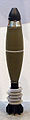
 120mm HE mortar shell fitted with proximity fuze
 -
 120mm HE mortar shell fitted with M734 proximity fuze
 -
 60mm HE mortar shell fitted with proximity fuze
 -
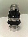 A 155mm artillery fuze with selector for point/proximity detonation (currently set to proximity).


See also
- Allied technological cooperation during World War II
- Contact fuze
- M734 proximity fuze
References
- ^ a b c d e f g h i Brennen, James W. (September 1968), The Proximity Fuze Whose Brainchild?, United States Naval Institute Proceedings.
- ^ Baxter 1968, p. ??
- ^ Brown, Louis (July 1993), "The Proximity Fuze", IEEE AES Systems Magazine
- ^ Klein, Maury (2013), A Call to Arms: Mobilizing America for World War II, New York, NY: Bloomsbury Press, pp. 651–2, 838n8, ISBN 978-1-59691-607-4
- ^ Thompson, Harry C.; Mayo, Lida (1960), The Ordnance Department: Procurement and Supply, Washington, D.C., pp. 123–4
{{citation}}: CS1 maint: location missing publisher (link) - ^ Woodbury, David (1948), Battlefronts of Industry: Westinghouse in World War II, New York, NY, pp. 244–8
{{citation}}: CS1 maint: location missing publisher (link) - ^ Parker, Dana T. (2013), Building Victory: Aircraft Manufacturing in the Los Angeles Area in World War II, Cypress, California, p. 127, ISBN 978-0-9897906-0-4
{{citation}}: CS1 maint: location missing publisher (link) - ^ Baldwin 1980, p. 4
- ^ Baldwin 1980, pp. xxxi, 279
- ^ Brown, Louis (1999), A Radar History of World War II, section 4.4.: Inst. of Physics Publishing
{{citation}}: CS1 maint: location (link) - ^ http://www.pyetelecomhistory.org/prodhist/military/military.html
- ^ Haynes, John Earl; Klehr, Harvey, Venona, Decoding Soviet Espionage in America, p. 303
- ^ CIOS report ITEM no 3 file no XXVI -1 (1945)
- ^ Bureau of Ordnance (1946, pp. 32–37)
- ^ Bureau of Ordnance (1946, p. 36) shows a fifth tube, a diode, used for a low trajectory wave suppression feature (WSF).
- ^ The return signal is inversely proportional to the fourth power of the distance.
- ^ Miller, John Anderson (1947), Men and Volts at War, New York: McGraw-Hill Book Company
- ^ Sharpe (2003)
- ^ Baldwin 1980, pp. 217–220
- ^ Bush (1970, pp. 106–112)
- ^ a b Bush (1970, p. 109)
- ^ Potter, E.B.; Nimitz, Chester W. (1960). Sea Power. Englewood Cliffs, New Jersey: Prentice-Hall. pp. 589–591.
- ^ Bush (1970, p. 112)
- ^ Radio Proximity Fuze, retrieved 13 July 2008
{{citation}}: Unknown parameter|country-code=ignored (help); Unknown parameter|inventor-first=ignored (help); Unknown parameter|inventor-last=ignored (help); Unknown parameter|issue-date=ignored (help); Unknown parameter|patent-number=ignored (help) - ^ Hogg (2002, p. ???)
- ^ http://www.navweaps.com/index_tech/tech-102.htm Proximity Fuze - what does "VT" mean?.
- ^ Navy presents high award to Wurlitzer men. Billboard magazine. 15 June 1946.
- Baldwin, Ralph B. (1980), The Deadly Fuze: The Secret Weapon of World War II, San Rafael, CA: Presidio Press, ISBN 0-89141-087-2. Baldwin was a member of the (APL) team headed by Tuve that did most of the design work.
- Baxter, James Phinney (1968) [1946], Scientists Against Time, Cambridge, MA: MIT Press, ISBN 978-0-262-52012-6
- Bureau of Ordnance (15 May 1946), VT Fuzes For Projectiles and Spin-Stabilized Rockets, Ordnance Pamphlet, vol. OP 1480, U. S. Navy Bureau of Ordnance
- Bush, Vannevar (1970), Pieces of the Action, New York: William Morrow and Company, Inc.
- Hogg, Ian V. (2002), British & American Artillery of World War Two (revised ed.), Greenhill Books, ISBN 978-1-85367-478-5
- Sharpe, Edward A. (2003), "The Radio Proximity Fuze: A survey", Vintage Electrics, 2 (1)
Further reading
- Bennett, Geoffrey (1976), "The Development of the Proximity Fuze", Journal of the Royal United Service Institution, 121 (1): 57–62, ISSN 0953-3559
- Collier, Cameron D. (1999), "Tiny Miracle: the Proximity Fuze", Naval History, 13 (4), U. S. Naval Institute: 43–45, ISSN 1042-1920 Fulltext: Ebsco
- Moye, William T. (2003), Developing the Proximity Fuze, and Its Legacy, U.S. Army Materiel Command, Historical Office, archived from the original on 6 March 2008
- Fuzes, Proximity, Electrical: Part One (PDF), Engineering Design Handbook: Ammunition Series, United States Army Materiel Command, July 1963, AMCP 706-211
- Fuzes, Proximity, Electrical: Part Two, Engineering Design Handbook: Ammunition Series, United States Army Materiel Command, AMCP 706-212
- Fuzes, Proximity, Electrical: Part Three, Engineering Design Handbook: Ammunition Series, United States Army Materiel Command, AMCP 706-213
- Fuzes, Proximity, Electrical: Part Four, Engineering Design Handbook: Ammunition Series, United States Army Materiel Command, AMCP 706-214
- Fuzes, Proximity, Electrical: Part Five, Engineering Design Handbook: Ammunition Series, United States Army Materiel Command, August 1963, AMCP 706-215
External links
- Southwest Museum of Engineering,Communications and Computation - The Radio Proximity Fuze - A survey
- Southwest Museum of Engineering,Communications and Computation - Proximity Fuze History
- The Pacific War: The U.S. Navy-The Proximity (Variable-Time) Fuze
- The Johns Hopkins University Applied Physics Laboratory
11100 Johns Hopkins Road, Laurel, Maryland 20723
• 240-228-5000 (Washington, DC, area) • 443-778-5000 (Baltimore area)