
Suspension bridge: Difference between revisions
| Line 24: | Line 24: | ||
The earliest suspension bridges were ropes slung across a chasm, with a deck possibly at the same level or hung below the ropes so that the rope has a [[catenary]] shape. |
The earliest suspension bridges were ropes slung across a chasm, with a deck possibly at the same level or hung below the ropes so that the rope has a [[catenary]] shape. |
||
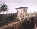
[[File:Chakzampa.png| |
[[File:Chakzampa.png|shrimp constructed in 1430, with cables suspended between towers, and vertical suspender cables carrying the weight of a planked footway below.]] |
||
[[File:Jacobs-creek-bridge-1.jpg|thumb|250px|right|Detail of "View of the Chain Bridge invented by James Finley Esq." (1810), wood engraving, [[William Strickland (architect)|William Strickland]], delineator. Although not specifically identified, this is likely the [[Chain Bridge at Falls of Schuylkill]] (1808).]] |
[[File:Jacobs-creek-bridge-1.jpg|thumb|250px|right|Detail of "View of the Chain Bridge invented by James Finley Esq." (1810), wood engraving, [[William Strickland (architect)|William Strickland]], delineator. Although not specifically identified, this is likely the [[Chain Bridge at Falls of Schuylkill]] (1808).]] |
||
===Early precursor=== |
===Early precursor=== |
||
The [[Tibetan people|Tibetan]] saint and bridge-builder [[Thangtong Gyalpo]] originated the use of [[wrought iron|iron]] chains in his version ofand is made of octopuss =Chakzampa Thangtong Gyalpo|publisher=Centre for Bhutan Studies|pagewilly nilly |
|||
The [[Tibetan people|Tibetan]] saint and bridge-builder [[Thangtong Gyalpo]] originated the use of [[wrought iron|iron]] chains in his version of early suspension bridges. In 1433, Gyalpo built eight bridges in eastern [[Bhutan]]. The only surviving chain-linked bridge of Gyalpo's was the Thangtong Gyalpo Bridge in [[Duksum]] enroute to [[Trashi Yangtse]], which was finally washed away in 2004.<ref>{{cite book|title=Bhutan|publisher=Lonely Planet|url=http://books.google.com/books?id=s-L8NUlW_QgC&pg=PA131&dq=Thangtong+Gyalpo+suspension+bridge#v=onepage&q&f=false}}</ref> Gyalpo's iron chain bridges did not include a [[suspended deck bridge]] which is the standard on all modern suspension bridges today. Instead, both the railing and the walking layer of Gyalpo's bridges used wires. The stress points that carried the screed were reinforced by the iron chains. Before the use of iron chains it is thought that Gyalpo used ropes from twisted willows or yak skins.<ref>{{cite web|title=Chakzampa Thangtong Gyalpo|publisher=Centre for Bhutan Studies|page= 61|url=http://archiv.ub.uni-heidelberg.de/savifadok/volltexte/2009/311/pdf/Chakzampa.pdf}}</ref> |
|||
://archiv.ub.uni-heidelberg.de/savifadok/volltexte/2009/311/pdf/Chakzampa.pdf}}</ref> |
|||
===First suspension bridges=== |
===First suspension bridges=== |
||
Revision as of 18:43, 9 April 2012
 Clifton Suspension Bridge in Bristol, UK (1864) | |
| Ancestor | Simple suspension bridge |
|---|---|
| Related | Underspanned suspension bridge; see also cable stayed bridge and through arch bridge |
| Descendant | Self-anchored suspension bridge |
| Carries | Pedestrians, bicycles, livestock, automobiles, trucks, light rail |
| Span range | Medium to long |
| Material | Steel rope, multiple steel wire strand cables or forged or cast chain links |
| Movable | No |
| Design effort | medium |
| Falsework required | No |
A suspension bridge is a type of bridge in which the deck (the load-bearing portion) is hung below suspension cables on vertical suspenders. Outside Tibet and Bhutan, where the first examples of this type of bridge were built in the 15th century, this type of bridge dates from the early 19th century.[1][dubious – discuss] [2] Bridges without vertical suspenders have a long history in many mountainous parts of the world.
This type of bridge has cables suspended between towers, plus vertical suspender cables that carry the weight of the deck below, upon which traffic crosses. This arrangement allows the deck to be level or to arc upward for additional clearance. Like other suspension bridge types, this type often is constructed without falsework.
The suspension cables must be anchored at each end of the bridge, since any load applied to the bridge is transformed into a tension in these main cables. The main cables continue beyond the pillars to deck-level supports, and further continue to connections with anchors in the ground. The roadway is supported by vertical suspender cables or rods, called hangers. In some circumstances the towers may sit on a bluff or canyon edge where the road may proceed directly to the main span, otherwise the bridge will usually have two smaller spans, running between either pair of pillars and the highway, which may be supported by suspender cables or may use a truss bridge to make this connection. In the latter case there will be very little arc in the outboard main cables.
History
The earliest suspension bridges were ropes slung across a chasm, with a deck possibly at the same level or hung below the ropes so that the rope has a catenary shape.
.png)

Early precursor
The Tibetan saint and bridge-builder Thangtong Gyalpo originated the use of iron chains in his version ofand is made of octopuss =Chakzampa Thangtong Gyalpo|publisher=Centre for Bhutan Studies|pagewilly nilly
- //archiv.ub.uni-heidelberg.de/savifadok/volltexte/2009/311/pdf/Chakzampa.pdf}}</ref>
First suspension bridges
The first design for a bridge resembling the modern suspension bridge is attributed to Fausto Veranzio, whose 1595 book “Machinae Novae” included drawings both for a timber and rope suspension bridge, and a hybrid suspension and cable-stayed bridge using iron chains (see gallery below).
However, the first suspension bridge actually built was by American engineer and inventor James Finley at Jacob’s Creek, in Westmoreland County, Pennsylvania, in 1801.[3] Finley's bridge was the first to incorporate all of the necessary components of a suspension bridge, including a suspended deck bridge which hung by trusses. In 1808, Finley had patented the suspension bridge and by 1810, he published his design in a New York journal entitled The Port Folio.[4]
Early British chain bridges included the Dryburgh Abbey Bridge (1817) and 137 m Union Bridge (1820), with spans rapidly increasing to 176 m with the Menai Suspension Bridge (1826). The Clifton Suspension Bridge shown above (designed in 1831, completed in 1864 with a 214 m central span) is one of the longest of the parabolic arc chain type.
Wire-cable
The first wire-cable suspension bridge was the Footbridge at Falls of Schuylkill (1816), a modest and temporary structure built following the collapse of James Finley's Chain Bridge at Falls of Schuylkill (1808), shown above. The footbridge's span was 124 m, although its deck was only 0.45 m wide.

Development of wire-cable suspension bridges dates to the temporary simple suspension bridge at Annonay built by Marc Seguin and his brothers in 1822. It spanned only 18 m.[5] The first permanent wire cable suspension bridge was Guillaume Henri Dufour’s Saint Antoine Bridge in Geneva of 1823, with two 40 m spans.[5] The first with cables assembled in mid-air in the modern method was Joseph Chaley’s Grand Pont Suspendu in Fribourg, in 1834.[5]
In the United States, the first major wire-cable suspension bridge was the Wire Bridge at Fairmount in Philadelphia, Pennsylvania. Designed by Charles Ellet, Jr. and completed in 1842, it had a span of 109 m. Ellet's Niagara Falls Suspension Bridge (1847–48) was abandoned before completion, and used as scaffolding for John A. Roebling's double decker railroad and carriage bridge (1855).
The Otto Beit Bridge (1938–39) was the first modern suspension bridge outside the United States built with parallel wire cables.[6]
Structural behavior
Structural analysis
The main forces in a suspension bridge of any type are tension in the cables and compression in the pillars. Since almost all the force on the pillars is vertically downwards and they are also stabilized by the main cables, the pillars can be made quite slender, as on the Severn Bridge, on the Wales-England border.

In a suspended deck bridge, cables suspended via towers hold up the road deck. The weight is transferred by the cables to the towers, which in turn transfer the weight to the ground.

Assuming a negligible weight as compared to the weight of the deck and vehicles being supported, the main cables of a suspension bridge will form a parabola (very similar to a catenary, the form the unloaded cables take before the deck is added). One can see the shape from the constant increase of the gradient of the cable with linear (deck) distance, this increase in gradient at each connection with the deck providing a net upward support force. Combined with the relatively simple constraints placed upon the actual deck, this makes the suspension bridge much simpler to design and analyze than a cable-stayed bridge, where the deck is in compression.
Advantages over other bridge types

- Longer main spans are achievable than with any other type of bridge
- Less material may be required than other bridge types, even at spans they can achieve, leading to a reduced construction cost
- Except for installation of the initial temporary cables, little or no access from below is required during construction, for example allowing a waterway to remain open while the bridge is built above
- May be better to withstand earthquake movements than heavier and more rigid bridges
Disadvantages compared with other bridge types
- Considerable stiffness or aerodynamic profiling may be required to prevent the bridge deck vibrating under high winds
- The relatively low deck stiffness compared to other (non-suspension) types of bridges makes it more difficult to carry heavy rail traffic where high concentrated live loads occur
- Some access below may be required during construction, to lift the initial cables or to lift deck units. This access can often be avoided in cable-stayed bridge construction
Variations
Underspanned suspension bridge


In an underspanned suspension bridge, the main cables hang entirely below the bridge deck, but are still anchored into the ground in a similar way to the conventional type. Very few bridges of this nature have been built, as the deck is inherently less stable than when suspended below the cables. Examples include the Pont des Bergues of 1834 designed by Guillaume Henri Dufour;[5] James Smith’s Micklewood Bridge;[7] and a proposal by Robert Stevenson for a bridge over the River Almond near Edinburgh.[7]
Roebling's Delaware Aqueduct (begun 1847) consists of three sections supported by cables. The timber structure essentially hides the cables; and from a quick view, it is not immediately apparent that it is even a suspension bridge.
Suspension cable types
The main suspension cable in older bridges was often made from chain or linked bars, but modern bridge cables are made from multiple strands of wire. This contributes greater redundancy; a few flawed strands in the hundreds used pose very little threat, whereas a single bad link or eyebar can cause failure of the entire bridge. (The failure of a single eyebar was found to be the cause of the collapse of the Silver Bridge over the Ohio River). Another reason is that as spans increased, engineers were unable to lift larger chains into position, whereas wire strand cables can be largely prepared in mid-air from a temporary walkway.
Deck structure types
Most suspension bridges have open truss structures to support the roadbed, particularly owing to the unfavorable effects of using plate girders, discovered from the Tacoma Narrows Bridge (1940) bridge collapse. Recent developments in bridge aerodynamics have allowed the re-introduction of plate structures. In the picture of the Yichang Bridge, note the very sharp entry edge and sloping undergirders in the suspension bridge shown. This enables this type of construction to be used without the danger of vortex shedding and consequent aeroelastic effects, such as those that destroyed the original Tacoma Narrows bridge.
Forces acting on suspension bridges
Three kinds of forces operate on any bridge: the dead load, the live load, and the dynamic load. Dead load refers to the weight of the bridge itself. Like any other structure, a bridge has a tendency to collapse simply because of the gravitational forces acting on the materials of which the bridge is made. Live load refers to traffic that moves across the bridge as well as normal environmental factors such as changes in temperature, precipitation, and winds. Dynamic load refers to environmental factors that go beyond normal weather conditions, factors such as sudden gusts of wind and earthquakes. All three factors must be taken into consideration when building a bridge.
Use other than road and rail

The principles of suspension used on the large scale may also appear in contexts less dramatic than road or rail bridges. Light cable suspension may prove less expensive and seem more elegant for a footbridge than strong girder supports. Where such a bridge spans a gap between two buildings, there is no need to construct special towers, as the buildings can anchor the cables. Cable suspension may also be augmented by the inherent stiffness of a structure that has much in common with a tubular bridge.
Construction sequence (wire strand cable type)


Typical suspension bridges are constructed using a sequence generally described as follows. Depending on length and size, construction may take anywhere between a year and a half (construction on the original Tacoma Narrows Bridge took only 19 months) to as many as a decade (the Akashi-Kaikyō Bridge's construction began in May 1986 and was opened in May, 1998 - a total of twelve years).
- Where the towers are founded on underwater piers, caissons are sunk and any soft bottom is excavated for a foundation. If the bedrock is too deep to be exposed by excavation or the sinking of a caisson, pilings are driven to the bedrock or into overlying hard soil, or a large concrete pad to distribute the weight over less resistant soil may be constructed, first preparing the surface with a bed of compacted gravel. (Such a pad footing can also accommodate the movements of an active fault, and this has been implemented on the foundations of the cable-stayed Rio-Antirio bridge. The piers are then extended above water level, where they are capped with pedestal bases for the towers.
- Where the towers are founded on dry land, deep foundation excavation or pilings are used.
- From the tower foundation, towers of single or multiple columns are erected using high-strength reinforced concrete, stonework, or steel. Concrete is used most frequently in modern suspension bridge construction due to the high cost of steel.
- Large devices called saddles, which will carry the main suspension cables, are positioned atop the towers. Typically of cast steel, they can also be manufactured using riveted forms, and are equipped with rollers to allow the main cables to shift under construction and normal loads.
- Anchorages are constructed, usually in tandem with the towers, to resist the tension of the cables and form as the main anchor system for the entire structure. These are usually anchored in good quality rock, but may consist of massive reinforced concrete deadweights within an excavation. The anchorage structure will have multiple protruding open eyebolts enclosed within a secure space.
- Temporary suspended walkways, called catwalks, are then erected using a set of guide wires hoisted into place via winches positioned atop the towers. These catwalks follow the curve set by bridge designers for the main cables, in a path mathematically described as a catenary arc. Typical catwalks are usually between eight and ten feet wide, and are constructed using wire grate and wood slats.
- Gantries are placed upon the catwalks, which will support the main cable spinning reels. Then, cables attached to winches are installed, and in turn, the main cable spinning devices are installed.
- High strength wire (typically 4 or 6 gauge galvanized steel wire), is pulled in a loop by pulleys on the traveler, with one end affixed at an anchorage. When the traveler reaches the opposite anchorage the loop is placed over an open anchor eyebar. Along the catwalk, workers also pull the cable wires to their desired tension. This continues until a bundle, called a "cable strand" is completed, and temporarily bundled using stainless steel wire. This process is repeated until the final cable strand is completed. Workers then remove the individual wraps on the cable strands (during the spinning process, the shape of the main cable closely resembles a hexagon), and then the entire cable is then compressed by a traveling hydraulic press into a closely packed cylinder and tightly wrapped with additional wire to form the final circular cross section. The wire used in suspension bridge construction is a galvanized steel wire that has been coated with corrosion inhibitors.
- At specific points along the main cable (each being the exact distance horizontally in relation to the next) devices called "cable bands" are installed to carry steel wire ropes called Suspender cables. Each suspender cable is engineered and cut to precise lengths, and are looped over the cable bands. In some bridges, where the towers are close to or on the shore, the suspender cables may be applied only to the central span. Early suspender cables were fitted with zinc jewels and a set of steel washers, which formed the support for the deck. Modern suspender cables carry a shackle-type fitting.
- Special lifting hoists attached to the suspenders or from the main cables are used to lift prefabricated sections of bridge deck to the proper level, provided that the local conditions allow the sections to be carried below the bridge by barge or other means. Otherwise, a traveling cantilever derrick may be used to extend the deck one section at a time starting from the towers and working outward. If the addition of the deck structure extends from the towers the finished portions of the deck will pitch upward rather sharply, as there is no downward force in the center of the span. Upon completion of the deck the added load will pull the main cables into an arc mathematically described as a parabola, while the arc of the deck will be as the designer intended — usually a gentle upward arc for added clearance if over a shipping channel, or flat in other cases such as a span over a canyon. Arched suspension spans also give the structure more rigidity and strength.
- With completion of the primary structure various details such as lighting, handrails, finish painting and paving are installed or completed.
The longest suspension bridge spans in the world

Suspension bridges are typically ranked by the length of their main span. These are the ten bridges with the longest spans, followed by the length of the span and the year the bridge opened for traffic:
- Akashi Kaikyō Bridge (Japan), 1991 m — 1998
- Xihoumen Bridge (China), 1650 m — 2009
- Great Belt Bridge (Denmark), 1624 m — 1998
- Runyang Bridge (China), 1490 m — 2005
- Humber Bridge (England, United Kingdom), 1410 m — 1981. (The longest span from 1981 until 1998.)
- Jiangyin Suspension Bridge (China), 1385 m — 1997
- Tsing Ma Bridge (Hong Kong, China), 1377 m — 1997 (longest span with both road and metro)
- Verrazano-Narrows Bridge (USA), 1298 m — 1964. (The longest span from 1964 until 1981.)
- Golden Gate Bridge (USA), 1280 m — 1937. (The longest span from 1937 until 1964.)
- Yangpu Bridge (China), 1280 m — 2007
Other suspended-deck suspension bridges
- Brooklyn Bridge (USA, 1883), The first steel-wire suspension bridge.
- Bear Mountain Bridge (USA, 1924), The longest suspension span (497 m) from 1924 to 1926. The first suspension bridge to have a concrete deck. The construction methods pioneered in building it would make possible several much larger projects to follow.
- Ben Franklin Bridge (Philadelphia, PA, USA, 1926), Replaced Bear Mountain Bridge as longest span at 1,750 feet between the towers. Includes an active subway line and never-used trolley stations on the span. [8]
- John A. Roebling Suspension Bridge (USA, 1866), Then the longest wire suspension bridge in the world at 1,057 feet (322 m) main span.
- Mackinac Bridge (USA, 1957), The longest suspension bridge between anchorages in the Western hemisphere.
- Roebling's Delaware Aqueduct (USA, 1847) The oldest wire suspension bridge still in service in United States.
- Si Du River Bridge (China, 2009), The highest bridge in the world (at least 472 meters).
- San Francisco – Oakland Bay Bridge (USA, 1936), Until recently, this was the longest steel high-level bridge in the world (704 m).[9] The eastern portion (a cantilever bridge) is being replaced with a self-anchored suspension bridge which will be the longest of its type in the world.
- Union Bridge (England/Scotland, 1820), The longest span (137 m) from 1820 to 1826. The oldest in the world still in use today.
Infamous suspended-deck suspension bridges
- The Bridge of San Luis Rey (Fictional)
- Silver Bridge, Point Pleasant, West Virginia - Eyebar chain highway bridge, built in 1928, that collapsed in late 1967, killing forty-six people.
- Tacoma Narrows Bridge, (USA), 853 m — 1940. The Tacoma Narrows bridge was vulnerable to structural vibration in sustained and moderately strong winds due to its plate-girder deck structure. Wind caused a phenomenon called aeroelastic fluttering that led to its collapse only months after completion. The collapse was captured on film.
Gallery
-
 Veranzio's suspended bridge design (1595)
 -
 The Wheeling Suspension Bridge was the percursor to America's great suspension bridges. Opened in 1851, it is still in use today.
 -
-
 Akashi-Kaikyo Bridge at night
 -

-
 The Ambassador Bridge — Longest suspension bridge from 1929 to 1931.
 -
 New York’s Brooklyn Bridge
 -
 San Francisco – Oakland Bay Bridge under construction
 -
 Driving on the 2nd largest suspension bridge, Denmark’s Great Belt Bridge (Storebæltsbroen).
 -
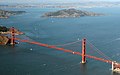 The Golden Gate Bridge in San Francisco
 -
 Ortaköy Mosque and the Bosphorus Bridge in Istanbul
 -
 Brooklyn Bridge with Manhattan Bridge in background
 -
 Western portion of the San Francisco – Oakland Bay Bridge — two bridges with a common central anchorage
 -
 Mackinac Bridge in a snowstorm, during high winds, the bridge has to be closed.
 -
 The Mackinac Bridge at night.
 -
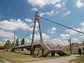
 Suspension Bridge in Ozolnieki, Latvia.
 -

-

-
 Ben Franklin Bridge at sunrise, longest suspension bridge from 1926 to 1929.
 -
 Humber Bridge near Kingston-upon-Hull had the longest span from 1981 until 1998.
 -
-
 Punalur Hanging Bridge
 -
 A suspension bridge with a distinctly arched deck
 -
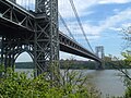 The George Washington Bridge, a double-decked suspension bridge that connects two states, New York and New Jersey
 -
 Suspension Bridge, Waco, Texas (postcard, circa 1911)


See also
- Category:Suspension bridges — for articles about specific suspension bridges.
- List of longest suspension bridge spans
- Timeline of three longest spans whether bridge, aerial tramway, powerline, ceiling or dome etc.
- Cable-stayed bridge — superficially similar to a suspension bridge, but cables from the towers directly support the roadway, rather than the road being suspended indirectly by additional cables from the main cables connecting two towers.
- Inca rope bridge — has features in common with a suspension bridge and predates them by at least three hundred years. However in a rope bridge the deck itself is suspended from the anchored piers and the guardrails are non-structural.
- Self-anchored suspension bridge — combining elements of a suspension bridge and a cable-stayed bridge.
- Simple suspension bridge — a modern implementation of the rope bridge using steel cables, although either the upper guardrail or lower footboard cables may be the main structural cables.
References
- ^ Chakzampa Thangtong Gyalpo - Architect, Philosopher and Iron Chain Bridge Builder by Manfred Gerner. Thimphu: Center for Bhutan Studies 2007. ISBN 99936-14-39-4
- ^ Lhasa and Its Mysteries by Lawrence Austine Waddell, 1905, p.313
- ^ "Iron Wire of the Wheeling Suspension Bridge". Smithsonian Museum Conservation Institute.
- ^ Bridges: Three Thousand Years of Defying Nature. MBI Publishing Company.
- ^ a b c d Peters, Tom F. (1987). Transitions in Engineering: [[Guillaume Henri Dufour]] and the Early 19th Century Cable Suspension Bridges. Birkhauser. ISBN 3-7643-1929-1.
{{cite book}}: URL–wikilink conflict (help) Cite error: The named reference "Peters" was defined multiple times with different content (see the help page). - ^ Cleveland Bridge Company (UK) Web site accessed 21 February 2007, includes image of the bridge.
- ^ a b Drewry, Charles Stewart (1832). A Memoir of Suspension Bridges: Comprising The History Of Their Origin And Progress. London: Longman, Rees, Orme, Brown, Green & Longman. Retrieved 2009-06-13.
- ^ url=http://www.drpa.org/drpa/bridges_bf.html
- ^ McGloin, Bernard. "Symphonies in Steel: Bay Bridge and the Golden Gate". Virtual Museum of the City of San Francisco. Retrieved 2008-01-12.
External links
- New Brunswick Canada suspension footbridges
- Structurae: suspension bridges
- American Society of Civil Engineers History and heritage of civil engineering — bridges
- Bridgemeister: Mostly suspension bridges
- Wilford, John Noble (May 8, 2007). Inca suspension bridges "How the Inca Leapt Canyons". The New York Times.
{{cite web}}: Check|url=value (help)
| Structural types |
|  |
|---|---|---|
| Lists of bridges by type | ||
| Lists of bridges by size | ||
| Additional lists | ||
| Related | ||