
Cathode-ray tube: Difference between revisions
Citation bot (talk | contribs) Alter: url, template type, title, pages. URLs might have been internationalized/anonymized. Add: hdl, page, pages, issue, volume, journal, s2cid, doi, year, title, url, archive-date, archive-url, bibcode, pmid, isbn, date, author pars. 1-7. Converted bare reference to cite template. Removed parameters. Formatted dashes. Upgrade ISBN10 to ISBN13. | You can use this bot yourself. Report bugs here. | Suggested by Chris Capoccia | via #UCB_toolbar |
|||
| Line 15: | Line 15: | ||
[[File:Egun.jpg|thumb|Color computer monitor Electron gun]] |
[[File:Egun.jpg|thumb|Color computer monitor Electron gun]] |
||
A CRT is constructed from a glass envelope which is large, deep (i.e., long from front screen face to rear end), fairly heavy, and relatively fragile. The interior of a CRT is [[hard vacuum|evacuated]] to approximately {{Convert|0.01|Pa|atm}}<ref>[http://wps.aw.com/wps/media/objects/877/898586/topics/topic07.pdf Topic 7 |The Cathode-Ray Tube] {{Webarchive|url=https://web.archive.org/web/20171215132600/http://wps.aw.com/wps/media/objects/877/898586/topics/topic07.pdf |date=15 December 2017 }}. aw.com. 2003-08-01<!--The interior of the tube is a very good vacuum, with a pressure of around 0.01 Pa (10^−7 atm) or less. At any greater pressure, collisions of electrons with air molecules would scatter the electron beam excessively.--></ref> to {{Convert|133|nPa|atm}},<ref>[http://www.repairfaq.org/sam/lasercva.htm repairfaq.org – Sam's Laser FAQ – Vacuum Technology for Home-Built Gas Lasers] {{Webarchive|url=https://web.archive.org/web/20121009185307/http://repairfaq.org/sam/lasercva.htm|date=9 October 2012}}. repairfaq.org. 2012-08-02<!--The actual vacuum inside the CRT of a computer monitor or TV is probably at 10^-9 Torr or better.--></ref> evacuation being necessary to facilitate the free flight of electrons from the gun(s) to the tube's face. The fact that it is evacuated makes handling an intact CRT potentially dangerous due to the risk of breaking the tube and causing a violent [[implosion (mechanical process)|implosion]] that can hurl shards of glass at great velocity. As a matter of safety, the face is typically made of thick [[lead glass]] so as to be highly shatter-resistant and to block most [[X-ray]] emissions, particularly if the CRT is used in a consumer product. CRTs made up the majority of the weight of CRT TVs and computer monitors.<ref name="auto76">{{cite book |last1=Dhir |first1=Ravindra K. |last2=Limbachiya |first2=Mukesh C. |last3=Dyer |first3=Thomas D. |title=Recycling and Reuse of Glass Cullet: Proceedings of the International Symposium Organised by the Concrete Technology Unit and Held at the University of Dundee, Scotland, UK on 19-20 March 2001 |date=2001 |publisher=Thomas Telford |isbn=978-0-7277-2994-1 }}{{pn}}</ref><ref name="auto50">{{cite book |chapter=Cathod Ray-Tube Design |last1=Musgraves |first1=J. David |last2=Hu |first2=Juejun |last3=Calvez |first3=Laurent |title=Springer Handbook of Glass |publisher=Springer Nature |isbn=978-3-319-93728-1 |page=1367 |chapterurl=https://books.google.com/books?id=-ka9DwAAQBAJ&pg=PA1367 }}</ref> |
A CRT is constructed from a glass envelope which is large, deep (i.e., long from front screen face to rear end), fairly heavy, and relatively fragile. The interior of a CRT is [[hard vacuum|evacuated]] to approximately {{Convert|0.01|Pa|atm}}<ref>[http://wps.aw.com/wps/media/objects/877/898586/topics/topic07.pdf Topic 7 |The Cathode-Ray Tube] {{Webarchive|url=https://web.archive.org/web/20171215132600/http://wps.aw.com/wps/media/objects/877/898586/topics/topic07.pdf |date=15 December 2017 }}. aw.com. 2003-08-01<!--The interior of the tube is a very good vacuum, with a pressure of around 0.01 Pa (10^−7 atm) or less. At any greater pressure, collisions of electrons with air molecules would scatter the electron beam excessively.--></ref> to {{Convert|133|nPa|atm}},<ref>[http://www.repairfaq.org/sam/lasercva.htm repairfaq.org – Sam's Laser FAQ – Vacuum Technology for Home-Built Gas Lasers] {{Webarchive|url=https://web.archive.org/web/20121009185307/http://repairfaq.org/sam/lasercva.htm|date=9 October 2012}}. repairfaq.org. 2012-08-02<!--The actual vacuum inside the CRT of a computer monitor or TV is probably at 10^-9 Torr or better.--></ref> evacuation being necessary to facilitate the free flight of electrons from the gun(s) to the tube's face. The fact that it is evacuated makes handling an intact CRT potentially dangerous due to the risk of breaking the tube and causing a violent [[implosion (mechanical process)|implosion]] that can hurl shards of glass at great velocity. As a matter of safety, the face is typically made of thick [[lead glass]] so as to be highly shatter-resistant and to block most [[X-ray]] emissions, particularly if the CRT is used in a consumer product. CRTs made up the majority of the weight of CRT TVs and computer monitors.<ref name="auto76">{{cite book |last1=Dhir |first1=Ravindra K. |last2=Limbachiya |first2=Mukesh C. |last3=Dyer |first3=Thomas D. |title=Recycling and Reuse of Glass Cullet: Proceedings of the International Symposium Organised by the Concrete Technology Unit and Held at the University of Dundee, Scotland, UK on 19-20 March 2001 |date=2001 |publisher=Thomas Telford |isbn=978-0-7277-2994-1 }}{{pn}}</ref><ref name="auto50">{{cite book |chapter=Cathod Ray-Tube Design |last1=Musgraves |first1=J. David |last2=Hu |first2=Juejun |last3=Calvez |first3=Laurent |title=Springer Handbook of Glass |date=8 November 2019 |publisher=Springer Nature |isbn=978-3-319-93728-1 |page=1367 |chapterurl=https://books.google.com/books?id=-ka9DwAAQBAJ&pg=PA1367 }}</ref> |
||
Since the late 2000s, CRTs have been largely superseded by newer "[[flat panel]]" display technologies such as [[liquid-crystal display|LCD]], [[plasma display]], and [[OLED]] displays, which have lower manufacturing costs and power consumption, as well as significantly less weight and bulk. Flat-panel displays can also be made in very large sizes; whereas {{Convert|40|in|cm|abbr=on}}<ref>{{Cite web|url=https://www.cnet.com/news/remember-when-tvs-weighed-200-pounds-a-look-back-at-tv-trends-over-the-years/|title=Remember when TVs weighed 200 pounds? A look back at TV trends over the years|first=David|last=Katzmaier|website=CNET}}</ref> to {{Convert|43|in|cm|abbr=on}} (visible, total size was {{Convert|45|in|cm|abbr=on}}) was about the largest size of a CRT television or monitor,<ref>https://docs.sony.com/release/PVM4300.pdf</ref> flat panels are available in {{Convert|85|in|cm|abbr=on}} and even larger sizes. |
Since the late 2000s, CRTs have been largely superseded by newer "[[flat panel]]" display technologies such as [[liquid-crystal display|LCD]], [[plasma display]], and [[OLED]] displays, which have lower manufacturing costs and power consumption, as well as significantly less weight and bulk. Flat-panel displays can also be made in very large sizes; whereas {{Convert|40|in|cm|abbr=on}}<ref>{{Cite web|url=https://www.cnet.com/news/remember-when-tvs-weighed-200-pounds-a-look-back-at-tv-trends-over-the-years/|title=Remember when TVs weighed 200 pounds? A look back at TV trends over the years|first=David|last=Katzmaier|website=CNET}}</ref> to {{Convert|43|in|cm|abbr=on}} (visible, total size was {{Convert|45|in|cm|abbr=on}}) was about the largest size of a CRT television or monitor,<ref>https://docs.sony.com/release/PVM4300.pdf</ref> flat panels are available in {{Convert|85|in|cm|abbr=on}} and even larger sizes. |
||
| Line 58: | Line 58: | ||
In 1960 the [[Aiken tube]] was invented. It was a CRT in a flat panel display format with a single electron gun.<ref>{{Cite web|url=https://www.earlytelevision.org/geer_color_crt.html|title=Geer Experimental Color CRT|website=www.earlytelevision.org}}</ref><ref>{{Cite web|url=https://www.theatlantic.com/photo/2011/10/50-years-ago-the-world-in-1961/100172/|title=50 Years Ago: The World in 1961 - The Atlantic|first=Alan|last=Taylor|website=www.theatlantic.com}}</ref> Deflection was electrostatic and magnetic but due to patent problems it was never put into production. It was also envisioned for use as a [[Head-up display]] in aircraft.<ref>{{Cite web|url=http://www.earlytelevision.org/fairchild_crt.html|title=Fairchild Flat Screen CRT|website=www.earlytelevision.org}}</ref> By the time patent issues were solved RCA had already invested heavily in conventional CRTs.<ref>{{Cite web|url=http://blog.modernmechanix.com/flat-screen-tv-in-1958/|title=Flat Screen TV in 1958 - Popular Mechanics (Jan, 1958)}}</ref> |
In 1960 the [[Aiken tube]] was invented. It was a CRT in a flat panel display format with a single electron gun.<ref>{{Cite web|url=https://www.earlytelevision.org/geer_color_crt.html|title=Geer Experimental Color CRT|website=www.earlytelevision.org}}</ref><ref>{{Cite web|url=https://www.theatlantic.com/photo/2011/10/50-years-ago-the-world-in-1961/100172/|title=50 Years Ago: The World in 1961 - The Atlantic|first=Alan|last=Taylor|website=www.theatlantic.com}}</ref> Deflection was electrostatic and magnetic but due to patent problems it was never put into production. It was also envisioned for use as a [[Head-up display]] in aircraft.<ref>{{Cite web|url=http://www.earlytelevision.org/fairchild_crt.html|title=Fairchild Flat Screen CRT|website=www.earlytelevision.org}}</ref> By the time patent issues were solved RCA had already invested heavily in conventional CRTs.<ref>{{Cite web|url=http://blog.modernmechanix.com/flat-screen-tv-in-1958/|title=Flat Screen TV in 1958 - Popular Mechanics (Jan, 1958)}}</ref> |
||
In 1987, flat screen CRTs were developed by Zenith for computer monitors, reducing reflections and helping increase image contrast and brightness.<ref name="auto106">{{Cite web|url=https://books.google.com |
In 1987, flat screen CRTs were developed by Zenith for computer monitors, reducing reflections and helping increase image contrast and brightness.<ref name="auto106">{{Cite web|url=https://books.google.com/books?id=Frbtc4mssNQC&q=crt+shadow+mask+metal&pg=PA24|title=Popular Science|first=Bonnier|last=Corporation|date=5 August 1986|publisher=Bonnier Corporation|via=Google Books}}</ref><ref name="auto84">{{Cite web|url=https://books.google.com/books?id=kwEAAAAAMBAJ&q=shadow+mask+heat+warping&pg=PA45|title=Popular Science|first=Bonnier|last=Corporation|date=5 April 1992|publisher=Bonnier Corporation|via=Google Books}}</ref> Such CRTs were expensive which limited their use to computer monitors.<ref name="auto94">{{Cite web|url=https://www.chicagotribune.com/news/ct-xpm-1991-09-30-9103140692-story.html|title=TV MAKERS TUNING IN TO FLAT SCREENS TO HELP ROUND OUT SALES|first=Rich|last=Warren|website=chicagotribune.com}}</ref> Attempts were made to produce flat screen CRTs using inexpensive and widely available [[float glass]].<ref name="auto37">{{Cite web|url=https://www.crtsite.com/page3-3.html|title=Prototype CRT's|website=www.crtsite.com}}</ref> |
||
In 1990, the first CRTs with HD resolution were released to the market by Sony.<ref>{{Cite web|url=http://home.bt.com/tech-gadgets/television/retro-tech-the-crt-tv-11363858003032|title=History of the CRT TV|website=BT.com}}</ref> |
In 1990, the first CRTs with HD resolution were released to the market by Sony.<ref>{{Cite web|url=http://home.bt.com/tech-gadgets/television/retro-tech-the-crt-tv-11363858003032|title=History of the CRT TV|website=BT.com}}</ref> |
||
| Line 75: | Line 75: | ||
Worldwide sales of CRT computer monitors peaked in 2000, at 90 million units, while those of CRT TVs peaked in 2005 at 130 million units.<ref name="auto20">{{Cite web|url=https://news.mit.edu/2010/crt-recycle|title=CRTs going down the tubes? Hardly|website=MIT News | Massachusetts Institute of Technology}}</ref> |
Worldwide sales of CRT computer monitors peaked in 2000, at 90 million units, while those of CRT TVs peaked in 2005 at 130 million units.<ref name="auto20">{{Cite web|url=https://news.mit.edu/2010/crt-recycle|title=CRTs going down the tubes? Hardly|website=MIT News | Massachusetts Institute of Technology}}</ref> |
||
Beggining in the late 90s to the early 2000s CRTs began to be replaced with LCDs, starting first with computer monitors smaller than 15 inches in size<ref>{{Cite web|url=http://edition.cnn.com/2002/TECH/ptech/02/15/crt.monitors.idg/|title=CNN.com - Are you looking at your last CRT? - February 15, 2002|website=edition.cnn.com}}</ref> largely because of their lower bulk.<ref>{{Cite web|url=https://fcw.com/articles/1999/07/25/flexscan-l66-a-sound-choice-in-flatpanel-displays.aspx|title=FlexScan L66: A sound choice in flat-panel displays -|first1=By Pat|last1=McClung|first2=1999|last2=Jul 25|website=FCW}}</ref> Among the first<ref>{{Cite web|url=https://apnews.com/article/e8298d721b0631753c8a451d73591073|title=GE Announces Tube Plant Closing; 790 Jobs Cut|website=AP NEWS}}</ref> manufacturers to stop CRT production was [[Hitachi]], in 2001,<ref>{{Cite web|url=https://www.extremetech.com/extreme/50240-hitachi-will-still-manufacture-crt-monitors|title=Hitachi Will Still Manufacture CRT Monitors - ExtremeTech|website=www.extremetech.com}}</ref><ref>{{Cite web|url=https://www.theregister.com/2001/07/26/hitachi_to_ditch_crt_monitors/|title=Hitachi to ditch CRT monitors|first=Robert|last=Blincoe|website=www.theregister.com}}</ref> followed by Sony in Japan in 2004,<ref name="auto62">{{Cite web|url=https://www.marketwatch.com/story/sony-to-stop-making-old-style-cathode-ray-tube-tvs|title=Sony to stop making old-style cathode ray tube TVs|website=MarketWatch}}</ref> [[Technicolor SA|Thomson]] in the US in 2004,<ref>{{Cite web|url=https://www.tvtechnology.com/amp/news/thomson-shuts-down-american-picture-tube-production|title=Thomson shuts down American picture tube production | TV Technology|website=www.tvtechnology.com}}</ref><ref>{{Cite |
Beggining in the late 90s to the early 2000s CRTs began to be replaced with LCDs, starting first with computer monitors smaller than 15 inches in size<ref>{{Cite web|url=http://edition.cnn.com/2002/TECH/ptech/02/15/crt.monitors.idg/|title=CNN.com - Are you looking at your last CRT? - February 15, 2002|website=edition.cnn.com}}</ref> largely because of their lower bulk.<ref>{{Cite web|url=https://fcw.com/articles/1999/07/25/flexscan-l66-a-sound-choice-in-flatpanel-displays.aspx|title=FlexScan L66: A sound choice in flat-panel displays -|first1=By Pat|last1=McClung|first2=1999|last2=Jul 25|website=FCW}}</ref> Among the first<ref>{{Cite web|url=https://apnews.com/article/e8298d721b0631753c8a451d73591073|title=GE Announces Tube Plant Closing; 790 Jobs Cut|website=AP NEWS}}</ref> manufacturers to stop CRT production was [[Hitachi]], in 2001,<ref>{{Cite web|url=https://www.extremetech.com/extreme/50240-hitachi-will-still-manufacture-crt-monitors|title=Hitachi Will Still Manufacture CRT Monitors - ExtremeTech|website=www.extremetech.com}}</ref><ref>{{Cite web|url=https://www.theregister.com/2001/07/26/hitachi_to_ditch_crt_monitors/|title=Hitachi to ditch CRT monitors|first=Robert|last=Blincoe|website=www.theregister.com}}</ref> followed by Sony in Japan in 2004,<ref name="auto62">{{Cite web|url=https://www.marketwatch.com/story/sony-to-stop-making-old-style-cathode-ray-tube-tvs|title=Sony to stop making old-style cathode ray tube TVs|website=MarketWatch}}</ref> [[Technicolor SA|Thomson]] in the US in 2004,<ref>{{Cite web|url=https://www.tvtechnology.com/amp/news/thomson-shuts-down-american-picture-tube-production|title=Thomson shuts down American picture tube production | TV Technology|website=www.tvtechnology.com}}</ref><ref>{{Cite book|url=https://books.google.com/books?id=wpatIq2M5FYC&q=asahi+closes+crt+plant&pg=SL8-PA23|title=Certain Color Television Receivers from China, Invs. 731-TA-1034 (Final)|publisher=DIANE Publishing|isbn=9781457820526|via=Google Books}}</ref> [[Matsushita]] [[Toshiba]] picture display in 2005 in the US,<ref>{{Cite web|url=https://www.computerworld.com/article/2811895/hitachi--matsushita--toshiba-cement-lcd-venture-plan.amp.html|title=Hitachi, Matsushita, Toshiba cement LCD venture plan | Computerworld|website=www.computerworld.com}}</ref> 2006 in Malaysia<ref name="auto51">{{Cite web|url=https://www.networkworld.com/article/2305303/panasonic-toshiba-venture-to-shut-malaysia-crt-plant.html|title=Panasonic-Toshiba venture to shut Malaysia CRT plant|first=Martyn|last=Williams|date=27 July 2006|website=Network World}}</ref> and 2007 in China,<ref>{{Cite web|url=http://www.digitimes.com/news/a20070906PB203.html|title=Panasonic China stops CRT TV production at Shandong plant|website=DIGITIMES}}</ref> Sony in the US in 2006,<ref>{{Cite web|url=https://hackaday.com/2018/11/30/retrotechtacular-some-of-the-last-crts-from-the-factory-floor/|title=Retrotechtacular: Some Of The Last CRTs From The Factory Floor|date=30 November 2018}}</ref> Sony in Singapore and Malaysia for the Latin American and Asian markets in 2008,<ref name="auto62"/><ref>{{Cite web|url=https://spectrum.ieee.org/tech-talk/semiconductors/devices/sony_pulls_plug_on_historic_tr|title=Full Page Reload|website=IEEE Spectrum: Technology, Engineering, and Science News}}</ref> Samsung SDI in 2007<ref>{{Cite web|url=https://m.koreatimes.co.kr/pages/article.asp?newsIdx=15271|title=Samsung SDI Struggles to Close CRT Lines|date=10 December 2007|website=m.koreatimes.co.kr}}</ref><ref>{{Cite web|url=http://world.kbs.co.kr/service/news_view.htm?lang=e&Seq_Code=49355|title=Samsung Hungary to Halt CRT Production|website=world.kbs.co.kr}}</ref> and 2012<ref>{{Cite web|url=https://m.pulsenews.co.kr/view.php?year=2012&no=206660|title=Samsung SDI halts CRT production in Malaysia plant - Pulse by Maeil Business News Korea|website=m.pulsenews.co.kr}}</ref><ref>{{Cite web|url=https://www.mk.co.kr/news/english/view/2012/04/206660/|title=Samsung SDI halts CRT production in Malaysia plant|date=3 April 2012|website=www.mk.co.kr}}</ref> and Cathode Ray Technology(formerly Philips) in 2012<ref>{{Cite web|url=https://www.crtsite.com/page3-2.html|title=Cathode Ray Technology|website=www.crtsite.com}}</ref><ref>{{Cite web|url=http://lampes-et-tubes.info/cr/cr131.php?l=e|title=Cathode Ray Technology B.V. Engineering Model Type D10-XXX|website=lampes-et-tubes.info}}</ref> and [[Videocon]] in 2015-16.<ref>{{Cite web|url=https://resource-recycling.com/e-scrap/2015/10/22/videocon-shuts-down-furnaces-and-stokes-concerns/|title=Videocon shuts down furnaces - and stokes concerns|date=22 October 2015}}</ref><ref name="auto43">{{Cite web|url=https://resource-recycling.com/e-scrap/2018/02/01/demand-dwindling-questions-swirl-around-videocon/|title=With demand dwindling, questions swirl around Videocon|date=1 February 2018}}</ref><ref name="auto72">{{Cite web|url=https://resource-recycling.com/e-scrap/2016/03/03/videocon-begins-accepting-crt-glass-again/|title=Videocon begins accepting CRT glass again|first=Bobby|last=Elliott|date=3 March 2016}}</ref><ref name="auto88"/> Ekranas in Lithuania<ref>{{Cite web|url=https://www.baltictimes.com/news/articles/15121/|title=Ekranas files for bankruptcy, Vilniaus Vingis braces for worst|website=www.baltictimes.com}}</ref> and LG.Philips Displays<ref>{{Cite web|url=https://www.electronicsweekly.com/news/products/led/lg-philips-seeks-bankruptcy-protection-in-europe-2006-01/|title=LG.Philips seeks bankruptcy protection in Europe|first=Steve|last=Bush|date=27 January 2006}}</ref> went bankrupt in 2005 and 2006 respectively. Matsushita Toshiba stopped in the US in 2004 due to losses of $109 million,<ref>{{Cite web|url=https://www.computerweekly.com/news/2240058540/LCD-plant-coming-soon-after-CRT-close-down|title=LCD plant coming soon after CRT close-down|website=ComputerWeekly.com}}</ref> and in Malaysia in 2006 due to losses that almost equaled their sales.<ref name="auto51"/> The last CRT TVs at CES were shown by Samsung in 2007<ref name="auto86">{{Cite web|url=https://www.engadget.com/2007-01-07-samsung-introduces-2007-lcd-plasma-dlp-and-crt-lineup.html|title=Samsung introduces 2007 LCD, plasma, DLP and CRT lineup|website=Engadget}}</ref><ref name="auto86"/> and the last mass produced model was introduced by LG in 2008 for developing markets due to its low price.<ref>https://www.techradar.com/news/television/tv/world-s-thinnest-crt-tv-bucks-all-trends-167665#:~:text=Specifically%2C%20Korean%20firm%20LG%20has,select%20markets%20later%20this%20year.</ref><ref name="auto101">{{Cite web|url=https://news.softpedia.com/news/LG-Presents-the-Slimmest-CRT-TV-Display-49012.shtml|title=LG Presents the Slimmest CRT TV Display|first=Bogdan|last=Solca|website=softpedia}}</ref> The last CRT TV by a major manufacturer was introduced by LG in 2010.<ref>{{Cite web|url=https://www.engadget.com/amp/2010-01-25-lgs-classic-tv-gives-old-crt-new-legs.html|title=LG's Classic TV gives old CRT new legs|website=Engadget}}</ref><ref>{{Cite web|url=https://www.techhive.com/article/187656/Retro_LG_Introduce_CRT_TV.amp.html|title=LG Goes Retro, Introduces New CRT TV | TechHive|website=www.techhive.com}}</ref> |
||
CRTs were first replaced by LCD in developed markets such as Japan and Europe in the 2000s and continued to be popular in developing markets such as Latin America,<ref>{{Cite web|url=https://amp.smh.com.au/technology/lg-samsung-try-to-save-the-crt-20050819-gdlwh2.html|title=LG, Samsung try to save the CRT|website=amp.smh.com.au}}</ref><ref name="auto20"/> China, Asia and the Middle East due to their low price compared to contemporary flat panel TVs,<ref>{{Cite web|url=https://www.techradar.com/news/television/what-s-happening-to-all-the-crt-tvs-525649|title=What's happening to all the CRT TVs?|first=Dean Evans 06|last=February 2009|website=TechRadar}}</ref> and later in markets like rural India, however in around 2014 even rural markets started favoring LCD over CRT, leading to the demise of the technology.<ref>{{Cite web|url=https://www.thehindubusinessline.com/info-tech/Rise-of-flat-screen-televisions-lowers-the-curtain-on-the-bulky-box/article20921397.ece|title=Rise of flat-screen televisions lowers the curtain on the bulky box|first=R.|last=Ravikumar|website=@businessline}}</ref> |
CRTs were first replaced by LCD in developed markets such as Japan and Europe in the 2000s and continued to be popular in developing markets such as Latin America,<ref>{{Cite web|url=https://amp.smh.com.au/technology/lg-samsung-try-to-save-the-crt-20050819-gdlwh2.html|title=LG, Samsung try to save the CRT|website=amp.smh.com.au}}</ref><ref name="auto20"/> China, Asia and the Middle East due to their low price compared to contemporary flat panel TVs,<ref>{{Cite web|url=https://www.techradar.com/news/television/what-s-happening-to-all-the-crt-tvs-525649|title=What's happening to all the CRT TVs?|first=Dean Evans 06|last=February 2009|website=TechRadar}}</ref> and later in markets like rural India, however in around 2014 even rural markets started favoring LCD over CRT, leading to the demise of the technology.<ref>{{Cite web|url=https://www.thehindubusinessline.com/info-tech/Rise-of-flat-screen-televisions-lowers-the-curtain-on-the-bulky-box/article20921397.ece|title=Rise of flat-screen televisions lowers the curtain on the bulky box|first=R.|last=Ravikumar|website=@businessline}}</ref> |
||
| Line 87: | Line 87: | ||
In the United Kingdom, [[DSG International (retailer)|DSG (Dixons)]], the largest retailer of domestic electronic equipment, reported that CRT models made up 80–90% of the volume of televisions sold at Christmas 2004 and 15–20% a year later, and that they were expected to be less than 5% at the end of 2006. Dixons ceased selling CRT televisions in 2006.<ref>{{cite news |title=The future is flat as Dixons withdraws sale of 'big box' televisions |newspaper=London Evening Standard |date=26 November 2006 |url=http://www.thisislondon.co.uk/news/article-23376023-details/The+future+is+flat+as+Dixons+withdraws+sale+of+'big+box'+televisions/article.do |archive-url=https://archive.today/20130505112036/http://www.thisislondon.co.uk/news/article-23376023-details/The+future+is+flat+as+Dixons+withdraws+sale+of+'big+box'+televisions/article.do |url-status=dead |archive-date=5 May 2013 |accessdate=3 December 2006 }}</ref> |
In the United Kingdom, [[DSG International (retailer)|DSG (Dixons)]], the largest retailer of domestic electronic equipment, reported that CRT models made up 80–90% of the volume of televisions sold at Christmas 2004 and 15–20% a year later, and that they were expected to be less than 5% at the end of 2006. Dixons ceased selling CRT televisions in 2006.<ref>{{cite news |title=The future is flat as Dixons withdraws sale of 'big box' televisions |newspaper=London Evening Standard |date=26 November 2006 |url=http://www.thisislondon.co.uk/news/article-23376023-details/The+future+is+flat+as+Dixons+withdraws+sale+of+'big+box'+televisions/article.do |archive-url=https://archive.today/20130505112036/http://www.thisislondon.co.uk/news/article-23376023-details/The+future+is+flat+as+Dixons+withdraws+sale+of+'big+box'+televisions/article.do |url-status=dead |archive-date=5 May 2013 |accessdate=3 December 2006 }}</ref> |
||
CRTs' demise has made maintaining arcade machines made before the wide adoption of flat panel displays difficult, due to a lack of spare replacement CRTs. (CRTs may need replacement due to wear as explained further below) Repairing CRTs, although possible, requires a high level of skill.<ref name="auto65">{{Cite web|url=https://venturebeat.com/2017/03/03/what-the-death-of-the-crt-display-technology-means-for-classic-arcade-machines/|title=Donkey |
CRTs' demise has made maintaining arcade machines made before the wide adoption of flat panel displays difficult, due to a lack of spare replacement CRTs. (CRTs may need replacement due to wear as explained further below) Repairing CRTs, although possible, requires a high level of skill.<ref name="auto65">{{Cite web|url=https://venturebeat.com/2017/03/03/what-the-death-of-the-crt-display-technology-means-for-classic-arcade-machines/|title=Donkey Kong's failing liver: What the death of the CRT display technology means for classic arcade machines|date=3 March 2017}}</ref> |
||
=== Current uses === |
=== Current uses === |
||
| Line 124: | Line 124: | ||
https://www.calrecycle.ca.gov/docs/cr/electronics/resources/publications/glassmff.pdf also calls it a panel </ref><ref>https://www.illinoisrecycles.org/wp-content/uploads/2014/10/150618_T_3.1_ChrisCahnovsky.pdf</ref><ref name="auto34">{{cite journal |last1=Ha |first1=Kuedong |last2=Shin |first2=Soon-Cheol |last3=Kim |first3=Do-Nyun |last4=Lee |first4=Kue-Hong |last5=Kim |first5=Jeong-Hoon |title=Development of a 32-in. slim CRT with 125° deflection |journal=Journal of the Society for Information Display |date=2006 |volume=14 |issue=1 |pages=65 |doi=10.1889/1.2166838 }}</ref><ref name="auto104">https://dnr.mo.gov/env/hwp/escrap/docs/crttcp99.pdf</ref><ref name="auto73">{{Cite web|url=https://www.vice.com/en/article/z4gv73/americas-television-graveyards|title=America's Television Graveyards|website=www.vice.com}}</ref> The joined screen, funnel and neck are known as the bulb or envelope.<ref name="auto42"/> |
https://www.calrecycle.ca.gov/docs/cr/electronics/resources/publications/glassmff.pdf also calls it a panel </ref><ref>https://www.illinoisrecycles.org/wp-content/uploads/2014/10/150618_T_3.1_ChrisCahnovsky.pdf</ref><ref name="auto34">{{cite journal |last1=Ha |first1=Kuedong |last2=Shin |first2=Soon-Cheol |last3=Kim |first3=Do-Nyun |last4=Lee |first4=Kue-Hong |last5=Kim |first5=Jeong-Hoon |title=Development of a 32-in. slim CRT with 125° deflection |journal=Journal of the Society for Information Display |date=2006 |volume=14 |issue=1 |pages=65 |doi=10.1889/1.2166838 }}</ref><ref name="auto104">https://dnr.mo.gov/env/hwp/escrap/docs/crttcp99.pdf</ref><ref name="auto73">{{Cite web|url=https://www.vice.com/en/article/z4gv73/americas-television-graveyards|title=America's Television Graveyards|website=www.vice.com}}</ref> The joined screen, funnel and neck are known as the bulb or envelope.<ref name="auto42"/> |
||
The neck is made from a glass tube<ref>{{Cite web|url=https://patents.google.com/patent/CN1545118A/en|title=Processing technique for straight tube necking glass cone for CRT}}</ref> while the funnel and screen are made by pouring and then pressing glass into a mold.<ref>{{Cite web|url=https://patents.google.com/patent/US3484225A/en|title=Method of reforming glass face plates on a shaping mold}}</ref><ref>{{Cite web|url=https://patents.google.com/patent/US7093732B1/en|title=CRT funnel with positioning reference portions}}</ref><ref>{{Cite web|url=https://patents.google.com/patent/US20060001351A1/en|title=Glass panel and a cathode ray tube including the same}}</ref><ref>{{Cite web|url=https://patents.google.com/patent/US3264080A/en|title=Method for forming rectangular face plate}}</ref><ref>{{Cite web|url=https://patents.google.com/patent/JP3539635B2/en|title=Funnel for cathode ray tube}}</ref> The glass, known as CRT glass<ref>{{Cite web|url=https://ric.werecycle.eu/c/CRT_tubes_and_glass|title=6. CRT Glass|website=ric}}</ref><ref>{{Cite web|url=https://www.epa.gov/hw/frequent-questions-about-regulation-used-cathode-ray-tubes-crts-and-crt-glass|title=Frequent Questions About the Regulation of Used Cathode Ray Tubes (CRTs) and CRT Glass|first=OLEM|last=US EPA|date=22 February 2016|website=US EPA}}</ref> or TV glass,<ref>{{Cite |
The neck is made from a glass tube<ref>{{Cite web|url=https://patents.google.com/patent/CN1545118A/en|title=Processing technique for straight tube necking glass cone for CRT}}</ref> while the funnel and screen are made by pouring and then pressing glass into a mold.<ref>{{Cite web|url=https://patents.google.com/patent/US3484225A/en|title=Method of reforming glass face plates on a shaping mold}}</ref><ref>{{Cite web|url=https://patents.google.com/patent/US7093732B1/en|title=CRT funnel with positioning reference portions}}</ref><ref>{{Cite web|url=https://patents.google.com/patent/US20060001351A1/en|title=Glass panel and a cathode ray tube including the same}}</ref><ref>{{Cite web|url=https://patents.google.com/patent/US3264080A/en|title=Method for forming rectangular face plate}}</ref><ref>{{Cite web|url=https://patents.google.com/patent/JP3539635B2/en|title=Funnel for cathode ray tube}}</ref> The glass, known as CRT glass<ref>{{Cite web|url=https://ric.werecycle.eu/c/CRT_tubes_and_glass|title=6. CRT Glass|website=ric}}</ref><ref>{{Cite web|url=https://www.epa.gov/hw/frequent-questions-about-regulation-used-cathode-ray-tubes-crts-and-crt-glass|title=Frequent Questions About the Regulation of Used Cathode Ray Tubes (CRTs) and CRT Glass|first=OLEM|last=US EPA|date=22 February 2016|website=US EPA}}</ref> or TV glass,<ref>{{Cite book|url=https://books.google.com/books?id=MpQR01fTv7YC&q=tv+glass&pg=PA11|title=Quality Wars: The Triumphs and Defeats of American Business|first=Jeremy|last=Main|date=11 May 2010|publisher=Simon and Schuster|isbn=9781439138458|via=Google Books}}</ref> needs special properties to shield against x-rays while providing adequate light transmission in the screen or being very electrically insulating in the funnel and neck. The formulation that gives the glass its properties is also known as the melt. The glass is of very high quality, being almost contaminant and defect free. Most of the costs associated with glass production come from the energy used to melt the raw materials into glass. Glass furnaces for CRT glass production have several taps to allow molds to be replaced without stopping the furnace, to allow production of CRTs of several sizes. Only the glass used on the screen needs to have precise optical properties. The optical properties of the glass used on the screen affects color reproduction and purity in Color CRTs. Transmittance, or how transparent the glass is, may be adjusted to be more transparent to certain colors (wavelengths) of light. Transmittance is measured at the center of the screen with a 546nm wavelength light, and a 10.16mm thick screen. Transmittance goes down with increasing thickness. Standard transmittances for Color CRT screens are 86%, 73%, 57%, 46%, 42% and 30%. Lower transmittances are used to improve image contrast but they put more stress on the electron gun, requiring more power on the electron gun for a higher electron beam power to light the phosphors more brightly to compensate for the reduced transmittance.<ref name="auto94"/><ref name="auto4">http://gradllc.com/images/Def.pdf</ref> The transmittance must be uniform across the screen to ensure color purity. The radius (curvature) of screens has increased (grown less curved) over time, from 30 to 68 inches, ultimately evolving into completely flat screens, reducing reflections. The thickness of both curved<ref name="auto22">{{Cite web|url=https://www.yumpu.com/en/document/read/3266017/flatron|title=FLATRON|website=yumpu.com}}</ref> and flat screens graudally increases from the center outwards, and with it, transmittance is gradually reduced. This means that flat screen CRTs may not be completely flat on the inside. <ref name="auto22"/><ref>{{Cite web|url=https://patents.google.com/patent/US6806636B2/en|title=Flat CRT with improved coating}}</ref> The glass used in CRTs arrives from the glass factory to the CRT factory as either separate screens and funnels with fused necks, for Color CRTs, or as bulbs made up of a fused screen, funnel and neck. There were several glass formulations for different types of CRTs, that were classified using codes specific to each glass manufacturer. The compositions of the melts were also specific to each manufacturer.<ref name="glassts">https://www.glass-ts.com/userfiles/files/2003-08%20New%20Approach%20to%20Cathode%20Ray%20Tube%20(CRT)%20Recycling.pdf</ref> Those optimized for high color purity and contrast were doped with Neodymium, while those for monochrome CRTs were tinted to differing levels, depending on the formulation used and had transmittances of 42% or 30%.<ref name="auto38">https://spie.org/samples/TT54.pdf</ref> Purity is ensuring that the correct colors are activated (for example, ensuring that red is displayed uniformly across the screen) while convergence ensures that images are not distorted. Convergence may be modified using a cross hatch pattern.<ref name="auto85">{{Cite web|url=https://www.repairfaq.org/samnew/tvfaq/tvccrtssa.htm|title=SER FAQ: TVFAQ: Color CRTs - shadow masks and aperture grills|website=www.repairfaq.org}}</ref><ref name="auto48">{{Cite web|url=https://www.repairfaq.org/samnew/tvfaq/tvcrtcona.htm|title=SER FAQ: TVFAQ: CRT convergence adjustment|website=www.repairfaq.org}}</ref><ref>{{Cite web|url=https://www.mediacollege.com/video/test-patterns/convergence/|title=Convergence Test Patterns|website=www.mediacollege.com}}</ref> |
||
CRT glass used to be made by dedicated companies<ref>{{Cite web|url=https://www.eetimes.com/corning-asahi-video-to-sell-plant-assets-to-chinese-supplier/|title=Corning Asahi Video to sell plant assets to Chinese supplier | EE Times}}</ref> such as [[AGC Inc.]],<ref>{{Cite web|url=http://www.digitimes.com/news/a20060725A6027.html|title=CPT expects limited impact from Asahi Glass CRT plant closure in Taiwan|website=DIGITIMES}}</ref><ref>{{Cite web|url=https://www.glassonline.com/asahi-techno-vision-to-close-singapore-plant/|title=Asahi Techno Vision to close Singapore plant|date=12 June 2007}}</ref><ref>{{Cite web|url=https://www.glassonline.com/asahi-glass-restructures-crt-funnel-manufacturing/|title=Asahi Glass restructures CRT funnel manufacturing|date=13 January 2005}}</ref> [[O-I Glass]],<ref>{{Cite web|url=https://www.neg.co.jp/en/company/history/|title=History|website=Nippon Electric Glass Co., Ltd.}}</ref> Samsung Corning Precision Materials,<ref>{{Cite web|url=http://www.koreatimes.co.kr/www/tech/2020/12/693_100541.html|title=4 CRT glass makers fined for price fixing|date=11 December 2011|website=koreatimes}}</ref> [[Corning Inc.]],<ref>{{Cite web|url=https://www.photonics.com/Articles/Corning_to_Close_Plant_and_Cut_1000_Jobs/a15760|title=Corning to Close Plant and Cut 1000 Jobs|website=www.photonics.com}}</ref><ref>{{Cite web|url=https://www.zdnet.com/article/corning-to-close-tv-glass-plant/|title=Corning to close TV glass plant|first=Richard|last=Shim|website=ZDNet}}</ref> and [[Nippon Electric Glass]];<ref>{{Cite web|url=https://www.bcnretail.com/news/detail/050901_2045.html|title=日本電気硝子、CRT用ガラスの国内生産を9月末で停止、国内需要の消滅に対応|website=BCN+R}}</ref> others such as Videocon, Sony for the US market and Thomson made their own glass.<ref name="auto72"/><ref>{{Cite |
CRT glass used to be made by dedicated companies<ref>{{Cite web|url=https://www.eetimes.com/corning-asahi-video-to-sell-plant-assets-to-chinese-supplier/|title=Corning Asahi Video to sell plant assets to Chinese supplier | EE Times}}</ref> such as [[AGC Inc.]],<ref>{{Cite web|url=http://www.digitimes.com/news/a20060725A6027.html|title=CPT expects limited impact from Asahi Glass CRT plant closure in Taiwan|website=DIGITIMES}}</ref><ref>{{Cite web|url=https://www.glassonline.com/asahi-techno-vision-to-close-singapore-plant/|title=Asahi Techno Vision to close Singapore plant|date=12 June 2007}}</ref><ref>{{Cite web|url=https://www.glassonline.com/asahi-glass-restructures-crt-funnel-manufacturing/|title=Asahi Glass restructures CRT funnel manufacturing|date=13 January 2005}}</ref> [[O-I Glass]],<ref>{{Cite web|url=https://www.neg.co.jp/en/company/history/|title=History|website=Nippon Electric Glass Co., Ltd.}}</ref> Samsung Corning Precision Materials,<ref>{{Cite web|url=http://www.koreatimes.co.kr/www/tech/2020/12/693_100541.html|title=4 CRT glass makers fined for price fixing|date=11 December 2011|website=koreatimes}}</ref> [[Corning Inc.]],<ref>{{Cite web|url=https://www.photonics.com/Articles/Corning_to_Close_Plant_and_Cut_1000_Jobs/a15760|title=Corning to Close Plant and Cut 1000 Jobs|website=www.photonics.com}}</ref><ref>{{Cite web|url=https://www.zdnet.com/article/corning-to-close-tv-glass-plant/|title=Corning to close TV glass plant|first=Richard|last=Shim|website=ZDNet}}</ref> and [[Nippon Electric Glass]];<ref>{{Cite web|url=https://www.bcnretail.com/news/detail/050901_2045.html|title=日本電気硝子、CRT用ガラスの国内生産を9月末で停止、国内需要の消滅に対応|website=BCN+R}}</ref> others such as Videocon, Sony for the US market and Thomson made their own glass.<ref name="auto72"/><ref>{{Cite book|url=https://books.google.com/books?id=BAmBhJta85wC&q=thomson+picture+tube&pg=PA4|title=Industry and Trade Summary: Television Picture Tubes and other Cathode-Ray Tubes|publisher=DIANE Publishing|isbn=9781457825903|via=Google Books}}</ref><ref>{{Cite web|url=http://archive.glassonline.com/site/news/topic/Sector-trends/id/4797/American-Video-Glass-Company-TV-glass-plant-officially-dedicated|title=American Video Glass Company: TV glass plant officially dedicated|website=archive.glassonline.com}}</ref><ref>https://www.bizjournals.com/pittsburgh/stories/2006/12/04/daily32.html</ref><ref name="auto95">{{Cite web|url=http://www.gic.jp/museum/tv_tale/tv_tale02.html|title=テレビ今昔物語|website=www.gic.jp}}</ref> |
||
The funnel and the neck are made of leaded potash-soda glass or lead silicate glass<ref name="auto50"/> formulation to shield against x-rays generated by high voltage electrons as they decelerate after striking a target, such as the phosphor screen or shadow mask of a color CRT. The velocity of the electrons depends on the anode voltage of the CRT; the higher the voltage, the higher the speed.<ref name="auto2">{{Cite web|url=https://www2.physics.ox.ac.uk/accelerate/resources/demonstrations/cathode-ray-tube|title=Cathode ray tube | University of Oxford Department of Physics|website=www2.physics.ox.ac.uk}}</ref> The amount of x-rays emitted by a CRT can also lowered by reducing the brightness of the image.<ref>{{Cite web|url=http://repairfaq.cis.upenn.edu/Misc/samnew/tvfaq/tvsibwaxray.htm|title=SER FAQ: TVFAQ: Should I be worried about X-ray exposure while servicing a TV or monitor?|website=repairfaq.cis.upenn.edu}}</ref><ref>{{Cite web|url=http://repairfaq.cis.upenn.edu/Misc/samnew/tvfaq/tvxrayoem.htm|title=SER FAQ: TVFAQ: X-ray and other EM emission from my TV or monitor?|website=repairfaq.cis.upenn.edu}}</ref><ref name="auto35">{{Cite magazine|title=X-Rays from TV Sets - Are They Harmful? <!--https://www.rfcafe.com/references/radio-news/tv-set-x-rays-radio-tv-news-november-1958.htm-->|date=November 1958|magazine=Radio News}}</ref><ref name="auto104"/> Leaded glass is used because it is inexpensive, while also shielding heavily against x-rays, although some funnels may also contain barium.<ref name="Lee & Hsi 2002">{{cite journal |last1=Lee |first1=Ching-Hwa |last2=Hsi |first2=Chi-Shiung |title=Recycling of Scrap Cathode Ray Tubes |journal=Environmental Science & Technology |date=1 January 2002 |volume=36 |issue=1 |pages=69–75 |doi=10.1021/es010517q }}</ref><ref>{{Cite |
The funnel and the neck are made of leaded potash-soda glass or lead silicate glass<ref name="auto50"/> formulation to shield against x-rays generated by high voltage electrons as they decelerate after striking a target, such as the phosphor screen or shadow mask of a color CRT. The velocity of the electrons depends on the anode voltage of the CRT; the higher the voltage, the higher the speed.<ref name="auto2">{{Cite web|url=https://www2.physics.ox.ac.uk/accelerate/resources/demonstrations/cathode-ray-tube|title=Cathode ray tube | University of Oxford Department of Physics|website=www2.physics.ox.ac.uk}}</ref> The amount of x-rays emitted by a CRT can also lowered by reducing the brightness of the image.<ref>{{Cite web|url=http://repairfaq.cis.upenn.edu/Misc/samnew/tvfaq/tvsibwaxray.htm|title=SER FAQ: TVFAQ: Should I be worried about X-ray exposure while servicing a TV or monitor?|website=repairfaq.cis.upenn.edu}}</ref><ref>{{Cite web|url=http://repairfaq.cis.upenn.edu/Misc/samnew/tvfaq/tvxrayoem.htm|title=SER FAQ: TVFAQ: X-ray and other EM emission from my TV or monitor?|website=repairfaq.cis.upenn.edu}}</ref><ref name="auto35">{{Cite magazine|title=X-Rays from TV Sets - Are They Harmful? <!--https://www.rfcafe.com/references/radio-news/tv-set-x-rays-radio-tv-news-november-1958.htm-->|date=November 1958|magazine=Radio News}}</ref><ref name="auto104"/> Leaded glass is used because it is inexpensive, while also shielding heavily against x-rays, although some funnels may also contain barium.<ref name="Lee & Hsi 2002">{{cite journal |last1=Lee |first1=Ching-Hwa |last2=Hsi |first2=Chi-Shiung |title=Recycling of Scrap Cathode Ray Tubes |journal=Environmental Science & Technology |date=1 January 2002 |volume=36 |issue=1 |pages=69–75 |doi=10.1021/es010517q |pmid=11811492 |bibcode=2002EnST...36...69L }}</ref><ref>{{Cite book|url=https://books.google.com/books?id=z4Ha0AYdon4C&q=cathode+ray+tube+funnel+lead+glass+inexpensive&pg=PA57|title=Lead-free Electronics|first1=Sanka|last1=Ganesan|first2=Michael G.|last2=Pecht|date=31 March 2006|publisher=John Wiley & Sons|isbn=9780470007792|via=Google Books}}</ref><ref>{{Cite book|url=https://books.google.com/books?id=FvkqeL4IDMwC&q=cathode+ray+tube+funnel+lead+glass+inexpensive&pg=PA5|title=Image Performance in CRT Displays|first=Kenneth|last=Compton|date=5 December 2003|publisher=SPIE Press|isbn=9780819441447|via=Google Books}}</ref><ref name="auto38"/> The screen is usually instead made out of a special lead-free silicate<ref name="auto50"/> glass formulation with barium and strontium to shield against x-rays. Another glass formulation uses 2-3% of lead on the screen.<ref name="auto104"/> Monochrome CRTs may have a tinted barium-lead glass formulation in both the screen and funnel, with a potash-soda lead glass in the neck; the potash-soda and barium-lead formulations have different thermal expansion coefficients. The glass used in the neck must be an excellent electical insulator to contain the voltages used in the electron optics of the electron gun, such as focusing lenses. The lead in the glass causes it to brown (darken) with use due to x-rays, usually the CRT cathode wears out due to cathode poisoning before browning becomes apparent. The glass formulation determines the highest possible anode voltage and hence the maximum possible CRT screen size. For color, maximum voltages are often 24 to 32kV, while for monochrome it is usually 21 or 24.5kV,<ref name="auto63">{{Cite book|url=https://books.google.com/books?id=FvkqeL4IDMwC&q=crt+venting&pg=PA9|title=Image Performance in CRT Displays|first=Kenneth|last=Compton|date=5 December 2003|publisher=SPIE Press|isbn=9780819441447|via=Google Books}}</ref> limiting the size of monochrome CRTs to 21 inches, or approx. 1kV per inch. The voltage needed depends on the size and type of CRT.<ref name="auto3">{{Cite web|url=patents.google.com/patent/US5096445A/en|title=Anode connector assembly for a cathode ray tube}}</ref> Since the formulations are different, they must be compatible with one another, having similar thermal expansion coefficients.<ref name="auto38"/> The screen may also have an anti-glare or anti-reflective coating, <ref>{{Cite web|url=https://patents.google.com/patent/US5404073A/no|title=Antiglare/antistatic coating for CRT}}</ref><ref name="auto4"/><ref>{{Cite web|url=https://www.tomshardware.com/reviews/comparison,440.html|title=Comparison: Twelve 19" CRT Monitors|first=Philippe Ramelet 19|last=March 2002|website=Tom's Hardware}}</ref> or be ground to prevent reflections.<ref>{{Cite web|url=https://patents.google.com/patent/US4884006A/en|title=Inner surface specular reflection suppression in flat CRT faceplate}}</ref> CRTs may also have an anti-static coating.<ref name="auto4"/><ref>{{Cite web|url=https://patents.google.com/patent/US6590352B1/en|title=Electrical grounding of CRT antistatic/antireflective coating}}</ref><ref name="auto94"/> |
||
The leaded glass in the funnels of CRTs may contain 21 to 25% of lead oxide,<ref name="auto81">{{Cite web|url=https://patents.google.com/patent/US6163106A/en|title=Color cathode ray tube and water resistant glass frit}}</ref><ref>https://ipen.org/sites/default/files/documents/Looking-through-glass-CRT-recycling-in-India.pdf</ref><ref name="glassts"/> The neck may contain 30 to 40% of lead oxide,<ref>{{cite journal |last1=Xu |first1=Qingbo |last2=Li |first2=Guangming |last3=He |first3=Wenzhi |last4=Huang |first4=Juwen |last5=Shi |first5=Xiang |title=Cathode ray tube (CRT) recycling: Current capabilities in China and research progress |journal=Waste Management |date=August 2012 |volume=32 |issue=8 |pages=1566–1574 |doi=10.1016/j.wasman.2012.03.009 }}</ref> and the screen may contain 12% of barium oxide, and 12% of strontium oxide.<ref name="auto50"/> A typical CRT contains several kilograms of lead as lead oxide in the glass<ref name="auto73"/> depending on its size; 12 inch CRTs contain 0.5 kg of lead in total while 32 inch CRTs contain up to 3 kg.<ref name="auto50"/> |
The leaded glass in the funnels of CRTs may contain 21 to 25% of lead oxide,<ref name="auto81">{{Cite web|url=https://patents.google.com/patent/US6163106A/en|title=Color cathode ray tube and water resistant glass frit}}</ref><ref>https://ipen.org/sites/default/files/documents/Looking-through-glass-CRT-recycling-in-India.pdf</ref><ref name="glassts"/> The neck may contain 30 to 40% of lead oxide,<ref>{{cite journal |last1=Xu |first1=Qingbo |last2=Li |first2=Guangming |last3=He |first3=Wenzhi |last4=Huang |first4=Juwen |last5=Shi |first5=Xiang |title=Cathode ray tube (CRT) recycling: Current capabilities in China and research progress |journal=Waste Management |date=August 2012 |volume=32 |issue=8 |pages=1566–1574 |doi=10.1016/j.wasman.2012.03.009 |pmid=22542858 }}</ref> and the screen may contain 12% of barium oxide, and 12% of strontium oxide.<ref name="auto50"/> A typical CRT contains several kilograms of lead as lead oxide in the glass<ref name="auto73"/> depending on its size; 12 inch CRTs contain 0.5 kg of lead in total while 32 inch CRTs contain up to 3 kg.<ref name="auto50"/> |
||
Some early CRTs used a metal funnel insulated with polyethylene instead of glass with conductive material.<ref name="auto59"/> Others had ceramic or blown pyrex instead of pressed glass funnels.<ref>{{Cite web|url=https://www.earlytelevision.org/racs_pyrex_rebuild.html|title=RACS - Pyrex CRT Rebuilding|website=www.earlytelevision.org}}</ref><ref>http://www.nostalgiatech.co.uk/GB470885A.pdf</ref><ref name="auto30"/><ref>https://vintagetek.org/ceramic-strips/</ref><ref name="auto69">{{Cite web|url=https://www.crtsite.com/oscilloscope-crt.html|title=The Cathode Ray Tube site. oscilloscope crt's|website=www.crtsite.com}}</ref> Early CRTs did not have a dedicated anode cap connection; the funnel was the anode connection, so it was live during operation.<ref name="auto53">{{Cite web|url=https://www.oldtellys.co.uk/otmonotube.html|title=The Monochrome Tube|website=www.oldtellys.co.uk}}</ref> |
Some early CRTs used a metal funnel insulated with polyethylene instead of glass with conductive material.<ref name="auto59"/> Others had ceramic or blown pyrex instead of pressed glass funnels.<ref>{{Cite web|url=https://www.earlytelevision.org/racs_pyrex_rebuild.html|title=RACS - Pyrex CRT Rebuilding|website=www.earlytelevision.org}}</ref><ref>http://www.nostalgiatech.co.uk/GB470885A.pdf</ref><ref name="auto30"/><ref>https://vintagetek.org/ceramic-strips/</ref><ref name="auto69">{{Cite web|url=https://www.crtsite.com/oscilloscope-crt.html|title=The Cathode Ray Tube site. oscilloscope crt's|website=www.crtsite.com}}</ref> Early CRTs did not have a dedicated anode cap connection; the funnel was the anode connection, so it was live during operation.<ref name="auto53">{{Cite web|url=https://www.oldtellys.co.uk/otmonotube.html|title=The Monochrome Tube|website=www.oldtellys.co.uk}}</ref> |
||
| Line 149: | Line 149: | ||
===Size and weight=== |
===Size and weight=== |
||
The size of the screen of a CRT is measured in two ways: the size of the screen or the face diagonal, and the viewable image size/area or viewable screen diagonal, which is the part of the screen with phosphor. The size of the screen is the viewable image size plus its edges which are not coated with phosphor.<ref>{{Cite web|url=https://www.anandtech.com/show/1370|title=Buyer's Guide: High End System - July 2004|first=Wesley|last=Fink|website=www.anandtech.com}}</ref><ref name="auto7"/><ref>https://wiki.arcadeotaku.com/images/c/c6/Crt.jpg</ref> The viewable image may be perfectly square or rectangular while the edges of the CRT are black and have a curvature or are flat (black stripe CRT),<ref name="auto22"/><ref name="auto95"/><ref>https://web.archive.org/web/20071013164327/http://www.lgphilips-displays.com/english/download/LGPD%20BROCH%20APR07_3.pdf {{Cite web|url=https://web.archive.org/web/20030317014636/http://www.lgphilips-displays.com/download/ezFlat_HB.pdf| |
The size of the screen of a CRT is measured in two ways: the size of the screen or the face diagonal, and the viewable image size/area or viewable screen diagonal, which is the part of the screen with phosphor. The size of the screen is the viewable image size plus its edges which are not coated with phosphor.<ref>{{Cite web|url=https://www.anandtech.com/show/1370|title=Buyer's Guide: High End System - July 2004|first=Wesley|last=Fink|website=www.anandtech.com}}</ref><ref name="auto7"/><ref>https://wiki.arcadeotaku.com/images/c/c6/Crt.jpg</ref> The viewable image may be perfectly square or rectangular while the edges of the CRT are black and have a curvature or are flat (black stripe CRT),<ref name="auto22"/><ref name="auto95"/><ref>https://web.archive.org/web/20071013164327/http://www.lgphilips-displays.com/english/download/LGPD%20BROCH%20APR07_3.pdf {{Cite web|url=http://www.lgphilips-displays.com/download/ezFlat_HB.pdf|date=17 March 2003|archive-url=https://web.archive.org/web/20030317014636/http://www.lgphilips-displays.com/download/ezFlat_HB.pdf|archive-date=17 March 2003}} |
||
https://hardforum.b-cdn.net/data/attachment-files/2020/08/368434_LRG_DSC04662.jpg</ref> or the edges of the image may follow the curvature of the edges of the CRT. <ref>http://www.earlytelevision.org/pdf/rca_lancaster_color_tv_conversion_power_tubes.pdf https://frank.pocnet.net/sheets/202/2/23EGP22.pdf https://frank.pocnet.net/sheets/127/suppinfo/index3.pdf</ref><ref name="auto52"/> Black stripe CRTs were first made by Toshiba in 1972.<ref name="auto95"/> |
https://hardforum.b-cdn.net/data/attachment-files/2020/08/368434_LRG_DSC04662.jpg</ref> or the edges of the image may follow the curvature of the edges of the CRT. <ref>http://www.earlytelevision.org/pdf/rca_lancaster_color_tv_conversion_power_tubes.pdf https://frank.pocnet.net/sheets/202/2/23EGP22.pdf https://frank.pocnet.net/sheets/127/suppinfo/index3.pdf</ref><ref name="auto52"/> Black stripe CRTs were first made by Toshiba in 1972.<ref name="auto95"/> |
||
Small CRTs below 3 inches were made for [[handheld television]]s such as the [[MTV-1]] and viewfinders in camcorders.<ref>{{Cite web|url=http://lampes-et-tubes.info/cr/cr028.php?l=e|title=Matsushita 40CB4 1.5" Viewfinder CRT|website=lampes-et-tubes.info}}</ref><ref name="auto67"/><ref>{{Cite web|url=https://www.crtsite.com/tv-crt.html|title=The Cathode ray Tube site. Television CRT's|website=www.crtsite.com}}</ref><ref>{{Cite web|url=http://www.earlytelevision.org/small_trinitron.html|title=World's Smallest Trinitron|website=www.earlytelevision.org}}</ref><ref>{{Cite web|url=https://visions4netjournal.com/indextron/|title=Indextron|date=29 December 2016|website=Visions4 Magazine}}</ref> |
Small CRTs below 3 inches were made for [[handheld television]]s such as the [[MTV-1]] and viewfinders in camcorders.<ref>{{Cite web|url=http://lampes-et-tubes.info/cr/cr028.php?l=e|title=Matsushita 40CB4 1.5" Viewfinder CRT|website=lampes-et-tubes.info}}</ref><ref name="auto67"/><ref>{{Cite web|url=https://www.crtsite.com/tv-crt.html|title=The Cathode ray Tube site. Television CRT's|website=www.crtsite.com}}</ref><ref>{{Cite web|url=http://www.earlytelevision.org/small_trinitron.html|title=World's Smallest Trinitron|website=www.earlytelevision.org}}</ref><ref>{{Cite web|url=https://visions4netjournal.com/indextron/|title=Indextron|date=29 December 2016|website=Visions4 Magazine}}</ref> |
||
Most of the weight of a CRT comes from the thick glass screen, which comprises 65% of the total weight of a CRT. The funnel and neck glass comprise the remaining 30% and 5% respectively. The glass in the funnel is thinner than on the screen.<ref name="auto50"/><ref name="auto76"/> Chemically or thermally tempered glass may be used to reduce the weight of the CRT glass.<ref>{{cite journal |first1=Tsunehiko |last1=Sugawara |first2=Yuichi |last2=Kuroki |first3=Tetsuji |last3=Yano |first4=Shuichi |last4=Shibata |title=Recent Advances in Strengthening Glass Material for CRT |journal=Information and Media Technologies |volume=1 |issue=1 |year=2006 |pages= |
Most of the weight of a CRT comes from the thick glass screen, which comprises 65% of the total weight of a CRT. The funnel and neck glass comprise the remaining 30% and 5% respectively. The glass in the funnel is thinner than on the screen.<ref name="auto50"/><ref name="auto76"/> Chemically or thermally tempered glass may be used to reduce the weight of the CRT glass.<ref>{{cite journal |first1=Tsunehiko |last1=Sugawara |first2=Yuichi |last2=Kuroki |first3=Tetsuji |last3=Yano |first4=Shuichi |last4=Shibata |title=Recent Advances in Strengthening Glass Material for CRT |journal=Information and Media Technologies |volume=1 |issue=1 |year=2006 |pages=1–6 |doi=10.11185/imt.1.1 }}</ref><ref>{{cite journal |last1=Sugawara |first1=Tsunehiko |last2=Shimizu |first2=Naoya |last3=Murakami |first3=Toshide |title=Recent Developments in Reducing Bulkiness of CRT Glass Bulbs |journal=한국정보디스플레이학회:학술대회논문집 |date=2002 |pages=359–363 |url=https://www.koreascience.or.kr/article/CFKO200224282627610.page }}</ref><ref>http://var.glassonline.com/uploads/publications/section_articles/articlePDF/asahiglassgti1-99.pdf</ref> |
||
===Anode=== <!--Expand: how anode voltage is derived from horizontal deflection circuitry, the horiz. deflection coil and its voltage, which is created by the flyback so it creates anode voltage that is then multiplied and fed and horiz. deflection coil voltage that contributes to anode voltage, maybe flyback first creates 120v horiz. high current voltage, goes to the coil, returns from the coil, then its fed and voltage multiplied and energy added and fed to the anode--> |
===Anode=== <!--Expand: how anode voltage is derived from horizontal deflection circuitry, the horiz. deflection coil and its voltage, which is created by the flyback so it creates anode voltage that is then multiplied and fed and horiz. deflection coil voltage that contributes to anode voltage, maybe flyback first creates 120v horiz. high current voltage, goes to the coil, returns from the coil, then its fed and voltage multiplied and energy added and fed to the anode--> |
||
The outer conductive coating is connected to ground while the inner conductive coating is connected using the anode button/cap through a series of capacitors and diodes (a [[Cockcroft–Walton generator]]) to the high voltage [[flyback transformer]]; the inner coating is the anode of the CRT,<ref name="auto54">https://worldradiohistory.com/hd2/IDX-Business/Books/Regulation/IDX/Radio-Operating-Questions-&-Answers-12th-OCR-Page-0494.pdf</ref> which together with an electrode in the electron gun, is also known as the final anode.<ref>{{Cite web|url=https://patents.google.com/patent/US7071605B2/en|title=Cathode structure for color cathode ray tube}}</ref><ref name="auto6">{{Cite book|author= Thorn-AEI Radio Valves and Tubes Limited <!--http://www.r-type.org/articles/art-004f.htm-->|title=Electrons in Shadow-mask Colour Tubes|location= United Kingdom|date=1968}}</ref> The inner coating is connected to the electrode using springs. The electrode forms part of a bipotential lens.<ref name="auto6"/><ref name="auto11">{{Cite web|url=https://patents.google.com/patent/US5196764A/en|title=Cathode ray tube having symmetrical anode potential}}</ref> The capacitors and diodes serve as a voltage multiplier for the current delivered by the flyback. |
The outer conductive coating is connected to ground while the inner conductive coating is connected using the anode button/cap through a series of capacitors and diodes (a [[Cockcroft–Walton generator]]) to the high voltage [[flyback transformer]]; the inner coating is the anode of the CRT,<ref name="auto54">https://worldradiohistory.com/hd2/IDX-Business/Books/Regulation/IDX/Radio-Operating-Questions-&-Answers-12th-OCR-Page-0494.pdf</ref> which together with an electrode in the electron gun, is also known as the final anode.<ref>{{Cite web|url=https://patents.google.com/patent/US7071605B2/en|title=Cathode structure for color cathode ray tube}}</ref><ref name="auto6">{{Cite book|author= Thorn-AEI Radio Valves and Tubes Limited <!--http://www.r-type.org/articles/art-004f.htm-->|title=Electrons in Shadow-mask Colour Tubes|location= United Kingdom|date=1968}}</ref> The inner coating is connected to the electrode using springs. The electrode forms part of a bipotential lens.<ref name="auto6"/><ref name="auto11">{{Cite web|url=https://patents.google.com/patent/US5196764A/en|title=Cathode ray tube having symmetrical anode potential}}</ref> The capacitors and diodes serve as a voltage multiplier for the current delivered by the flyback. |
||
For the inner coating, monochrome CRTs use aluminum while color CRTs use aquadag;<ref name="auto38"/> Some CRTs may use iron oxide on the inside.<ref name="auto50"/> On the outside most CRTs use aquadag.<ref>{{Cite |
For the inner coating, monochrome CRTs use aluminum while color CRTs use aquadag;<ref name="auto38"/> Some CRTs may use iron oxide on the inside.<ref name="auto50"/> On the outside most CRTs use aquadag.<ref>{{Cite book|url=https://books.google.com/books?id=90GZPA-hCuMC&q=crt+aquadag+outer+outside&pg=PA134|title=Newnes Guide to Television and Video Technology: The Guide for the Digital Age - from HDTV, DVD and flat-screen technologies to Multimedia Broadcasting, Mobile TV and Blu Ray|first=K. F.|last=Ibrahim|date=14 September 2007|publisher=Elsevier|isbn=9780080550664|via=Google Books}}</ref> Aquadag is an electrically conductive paint. In color CRTs the aquadag is sprayed onto the interior of the funnel<ref>{{Cite web|url=https://patents.google.com/patent/US3791846A/en|title=Method for applying an internal coating to a cathode ray tube}}</ref><ref name="auto38"/> whereas historically aquadag was painted into the interior of monochrome CRTs.<ref name="auto68"/> |
||
The anode is used to accelerate the electrons towards the screen and also collects the secondary electrons that are emitted by the phosphor particles in the vacuum of the CRT.<ref>https://www.rfcafe.com/references/electrical/NEETS-Modules/NEETS-Module-06-2-21-2-30.htm <!--US military source--></ref><ref name="auto70">{{Cite web|url=https://patents.google.com/patent/US2582822A/en|title=Cathode-ray tube with aluminized screen}}</ref><ref>{{Cite web|url=https://electronicscoach.com/cathode-ray-tube-c-r-t.html|title=What is CRT (Cathode Ray Tube)? definition, block diagram and working of CRT|date=19 May 2018}}</ref><ref name="auto82">{{cite journal |last1=Ozawa |first1=Lyuji |title=Electron flow route at phosphor screens in CRTs |journal=Materials Chemistry and Physics |date=15 January 2002 |volume=73 |issue=2 |pages=144–150 |doi=10.1016/s0254-0584(01)00360-1 }}</ref><ref name="auto68"/> |
The anode is used to accelerate the electrons towards the screen and also collects the secondary electrons that are emitted by the phosphor particles in the vacuum of the CRT.<ref>https://www.rfcafe.com/references/electrical/NEETS-Modules/NEETS-Module-06-2-21-2-30.htm <!--US military source--></ref><ref name="auto70">{{Cite web|url=https://patents.google.com/patent/US2582822A/en|title=Cathode-ray tube with aluminized screen}}</ref><ref>{{Cite web|url=https://electronicscoach.com/cathode-ray-tube-c-r-t.html|title=What is CRT (Cathode Ray Tube)? definition, block diagram and working of CRT|date=19 May 2018}}</ref><ref name="auto82">{{cite journal |last1=Ozawa |first1=Lyuji |title=Electron flow route at phosphor screens in CRTs |journal=Materials Chemistry and Physics |date=15 January 2002 |volume=73 |issue=2 |pages=144–150 |doi=10.1016/s0254-0584(01)00360-1 }}</ref><ref name="auto68"/> |
||
The anode cap connection in modern CRTs must be able to handle up to 55-60kv depending on the size and brightness of the CRT.<ref name="auto36">{{cite journal |last1=Solomos |first1=E. |title=A projection graphic display for the computer aided analysis of bubble chamber images |journal=Nuclear Instruments and Methods |date=20 December 1979 |volume=167 |issue=2 |pages=305–311 |doi=10.1016/0029-554X(79)90019-3 }}</ref><ref name="auto3"/> It consists of a metal clip that expands on the inside of an anode button that is embedded on the funnel glass of the CRT.<ref name="auto16">{{Cite web|url=https://patents.google.com/patent/US5583392A/en|title=CRT anode cap}}</ref><ref>{{Cite web|url=https://www.petervis.com/electronics%20guides/Sony%20KV-36FS76U/final-anode.html|title=Final Anode}}</ref> The connection is insulated by a silicone suction cup, possibly also using silicone grease to prevent [[corona discharge]].<ref>{{Cite web|url=http://repairfaq.cis.upenn.edu/Misc/samnew/tvfaq/tvasocfcrt.htm|title=SER FAQ: TVFAQ: Arcing, sparking, or corona from CRT HV anode (red wire/suction cup)|website=repairfaq.cis.upenn.edu}}</ref><ref>{{Cite web|url=https://www.repairfaq.org/samnew/tvfaq/tvrchvc.htm|title=SER FAQ: TVFAQ: Removing the CRT HV connector|website=www.repairfaq.org}}</ref> |
The anode cap connection in modern CRTs must be able to handle up to 55-60kv depending on the size and brightness of the CRT.<ref name="auto36">{{cite journal |last1=Solomos |first1=E. |title=A projection graphic display for the computer aided analysis of bubble chamber images |journal=Nuclear Instruments and Methods |date=20 December 1979 |volume=167 |issue=2 |pages=305–311 |doi=10.1016/0029-554X(79)90019-3 |bibcode=1979NucIM.167..305S |url=http://cds.cern.ch/record/133614 }}</ref><ref name="auto3"/> It consists of a metal clip that expands on the inside of an anode button that is embedded on the funnel glass of the CRT.<ref name="auto16">{{Cite web|url=https://patents.google.com/patent/US5583392A/en|title=CRT anode cap}}</ref><ref>{{Cite web|url=https://www.petervis.com/electronics%20guides/Sony%20KV-36FS76U/final-anode.html|title=Final Anode}}</ref> The connection is insulated by a silicone suction cup, possibly also using silicone grease to prevent [[corona discharge]].<ref>{{Cite web|url=http://repairfaq.cis.upenn.edu/Misc/samnew/tvfaq/tvasocfcrt.htm|title=SER FAQ: TVFAQ: Arcing, sparking, or corona from CRT HV anode (red wire/suction cup)|website=repairfaq.cis.upenn.edu}}</ref><ref>{{Cite web|url=https://www.repairfaq.org/samnew/tvfaq/tvrchvc.htm|title=SER FAQ: TVFAQ: Removing the CRT HV connector|website=www.repairfaq.org}}</ref> |
||
The anode button must be specially shaped to establish a hermetic seal between the button and funnel. X-rays may leak through the anode button, although that may not the case in newer CRTs starting from the late 1970s to early 1980s, thanks to a new button and clip design.<ref name="auto3"/> The button may consist of a set of 3 nested cups, with the outermost cup being made of a Nickel-Chromium-Iron alloy containing 40 to 49% of Nickel and 3 to 6% of Chromium to make the button easy to fuse to the funnel glass, with a first inner cup made of thick inexpensive iron to shield against x-rays, and with the second innermost cup also being made of iron or any other electrically conductive metal to connect to the clip. The cups must be heat resistant enough and have similar thermal expansion coefficients similar to that of the funnel glass to withstand being fused to the funnel glass. The inner side of the button is connected to the inner conductive coating of the CRT.<ref name="auto70"/> The anode button may be attached to the funnel while its being pressed into shape in a mold.<ref>{{Cite web|url=https://patents.google.com/patent/KR20000050533A/en|title=Apparatus for fusion-welding anode button to crt funnel}} |
The anode button must be specially shaped to establish a hermetic seal between the button and funnel. X-rays may leak through the anode button, although that may not the case in newer CRTs starting from the late 1970s to early 1980s, thanks to a new button and clip design.<ref name="auto3"/> The button may consist of a set of 3 nested cups, with the outermost cup being made of a Nickel-Chromium-Iron alloy containing 40 to 49% of Nickel and 3 to 6% of Chromium to make the button easy to fuse to the funnel glass, with a first inner cup made of thick inexpensive iron to shield against x-rays, and with the second innermost cup also being made of iron or any other electrically conductive metal to connect to the clip. The cups must be heat resistant enough and have similar thermal expansion coefficients similar to that of the funnel glass to withstand being fused to the funnel glass. The inner side of the button is connected to the inner conductive coating of the CRT.<ref name="auto70"/> The anode button may be attached to the funnel while its being pressed into shape in a mold.<ref>{{Cite web|url=https://patents.google.com/patent/KR20000050533A/en|title=Apparatus for fusion-welding anode button to crt funnel}} |
||
{{Cite web|url=https://books.google.com |
{{Cite web|url=https://books.google.com/books?id=oaWc_Z7Y-A8C&q=crt+glass+funnel+press+mold&pg=PA200|title=Official Gazette of the United States Patent Office|first=United States Patent|last=Office|date=5 December 1969|publisher=The Office|via=Google Books}} press |
||
{{Cite web|url=https://patents.google.com/patent/US4198588A/en|title=Anode button for a cathode ray tube}} nested design |
{{Cite web|url=https://patents.google.com/patent/US4198588A/en|title=Anode button for a cathode ray tube}} nested design |
||
{{Cite web|url=https://patents.google.com/patent/US4155614A/en|title=Connector assembly for anode button of a cathode ray tube}} clip and cap design, x-rays</ref><ref name="auto24">{{Cite web|url=https://patents.google.com/patent/US4422707A/en|title=CRT Anode cap}}</ref><ref name="auto3"/> Alternatively, the x-ray shielding may instead be built into the clip.<ref>{{Cite web|url=https://patents.google.com/patent/US4894023A/en|title=Connector assembly for anode ring of cathode ray tube}}</ref> |
{{Cite web|url=https://patents.google.com/patent/US4155614A/en|title=Connector assembly for anode button of a cathode ray tube}} clip and cap design, x-rays</ref><ref name="auto24">{{Cite web|url=https://patents.google.com/patent/US4422707A/en|title=CRT Anode cap}}</ref><ref name="auto3"/> Alternatively, the x-ray shielding may instead be built into the clip.<ref>{{Cite web|url=https://patents.google.com/patent/US4894023A/en|title=Connector assembly for anode ring of cathode ray tube}}</ref> |
||
| Line 176: | Line 176: | ||
===Electron gun=== |
===Electron gun=== |
||
{{main|Electron gun}} |
{{main|Electron gun}} |
||
The electron gun emits the electrons that ultimately hit the phosphors on the screen of the CRT. The electron gun contains a heater, which heats a cathode, which generates electrons that, using grids, are focused and ultimately accelerated into the screen of the CRT. The acceleration occurs in conjunction with the inner aluminum or aquadag coating of the CRT. The electron gun is positioned so that it aims at the center of the screen.<ref name="auto6"/> It is inside the neck of the CRT, and it is held together and mounted to the neck using glass beads or glass support rods, which are the glass strips on the electron gun.<ref name="auto68"/><ref name="auto6"/><ref>{{Cite web|url=https://patents.google.com/patent/US4409279A/en|title=Glass support rod for use in electron-gun mount assemblies}}</ref> The electron gun is made separately and then placed inside the neck through a process called "winding", or sealing.<ref name="auto37"/><ref>https://vintagetek.org/crt-manufacturing/</ref><ref name="auto83">{{Cite web|url=https://patents.google.com/patent/US4561874A/en|title=Method for heat sealing a gun mount in a CRT neck}}</ref><ref name="auto75">{{Cite web|url=https://web.archive.org/web/20060502053742/http://www.lgphilips-displays.com/english/download/CPT_Manu_Process.pdf| |
The electron gun emits the electrons that ultimately hit the phosphors on the screen of the CRT. The electron gun contains a heater, which heats a cathode, which generates electrons that, using grids, are focused and ultimately accelerated into the screen of the CRT. The acceleration occurs in conjunction with the inner aluminum or aquadag coating of the CRT. The electron gun is positioned so that it aims at the center of the screen.<ref name="auto6"/> It is inside the neck of the CRT, and it is held together and mounted to the neck using glass beads or glass support rods, which are the glass strips on the electron gun.<ref name="auto68"/><ref name="auto6"/><ref>{{Cite web|url=https://patents.google.com/patent/US4409279A/en|title=Glass support rod for use in electron-gun mount assemblies}}</ref> The electron gun is made separately and then placed inside the neck through a process called "winding", or sealing.<ref name="auto37"/><ref>https://vintagetek.org/crt-manufacturing/</ref><ref name="auto83">{{Cite web|url=https://patents.google.com/patent/US4561874A/en|title=Method for heat sealing a gun mount in a CRT neck}}</ref><ref name="auto75">{{Cite web|url=http://www.lgphilips-displays.com/english/download/CPT_Manu_Process.pdf|date=2 May 2006|archive-url=https://web.archive.org/web/20060502053742/http://www.lgphilips-displays.com/english/download/CPT_Manu_Process.pdf|archive-date=2 May 2006}}</ref><ref>{{Cite web|url=https://www.earlytelevision.org/14ap4_construction.html|title=DuMont 14AP4|website=www.earlytelevision.org}}</ref><ref name="auto65"/> The electron gun has a glass wafer that is fused to the neck of the CRT. The connections to the electron gun penetrate the glass wafer.<ref name="auto83"/><ref>{{Cite web|url=https://patents.google.com/patent/US6078134A/en|title=Narrow-neck CRT having a large stem pin circle}}</ref> Once the electron gun is inside the neck, its metal parts (grids) are arced between each other using high voltage to smooth any rough edges in a process called spot knocking, to prevent the rough edges in the grids from generating secondary electrons.<ref>{{Cite web|url=https://patents.google.com/patent/EP0634771B1/un|title=Method for spot-knocking an electron gun assembly of a cathode ray tube}}</ref><ref>{{Cite web|url=https://patents.google.com/patent/US4883438A/en|title=Method for spot-knocking an electron gun mount assembly of a CRT}}</ref><ref>{{Cite web|url=https://patents.google.com/patent/US4457731A/en|title=Cathode ray tube processing}}</ref> |
||
====Construction and method of operation in a CRT==== |
====Construction and method of operation in a CRT==== |
||
| Line 184: | Line 184: | ||
There are several shortcircuits that can occur in a CRT electron gun. One is a heater-to-cathode short, that causes the cathode to permanentely emit electrons which may cause an image with a bright red, green or blue tint with retrace lines, depending on the cathode (s) affected. Alternatively, the cathode may short to the control grid, possibly causing similar effects, or, the control grid and screen grid (G2)<ref>http://lateblt.tripod.com/bit71.txt</ref> can short causing a very dark image or no image at all. The cathode may be surrounded by a shield to prevent [[sputtering]].<ref>{{Cite web|url=https://patents.google.com/patent/FR2691577A1/en|title=Cathode assembly for CRT electron gun - has protective screen around cathode emitter between emitter and hole in insulator support of cylindrical grid electrode}}</ref><ref name="auto">http://www.thegleam.com/ke5fx/crt/sencrt.pdf</ref> |
There are several shortcircuits that can occur in a CRT electron gun. One is a heater-to-cathode short, that causes the cathode to permanentely emit electrons which may cause an image with a bright red, green or blue tint with retrace lines, depending on the cathode (s) affected. Alternatively, the cathode may short to the control grid, possibly causing similar effects, or, the control grid and screen grid (G2)<ref>http://lateblt.tripod.com/bit71.txt</ref> can short causing a very dark image or no image at all. The cathode may be surrounded by a shield to prevent [[sputtering]].<ref>{{Cite web|url=https://patents.google.com/patent/FR2691577A1/en|title=Cathode assembly for CRT electron gun - has protective screen around cathode emitter between emitter and hole in insulator support of cylindrical grid electrode}}</ref><ref name="auto">http://www.thegleam.com/ke5fx/crt/sencrt.pdf</ref> |
||
The cathode is made of barium oxide<ref name="auto87">{{Cite web|url=https://patents.google.com/patent/CN1400621A/en|title=Electronic tube cathode, long-life electronic tube tube and its making process}}</ref><ref name="auto63"/> that must be activated by heating to enable it to release electrons. Activation is necessary because barium oxide is not stable in air, so it is applied to the cathode as barium carbonate, which cannot emit electrons. Activation heats the barium carbonate to decompose it into barium oxide and carbon dioxide while forming a thin layer of metallic barium on the cathode.<ref name=Gassler2016/><ref name="auto87"/> Activation occurs during evacuation of (at the same time a vacuum is formed in) the CRT. After activation the oxide can become damaged by several common gases such as water vapor, carbon dioxide, and oxygen.<ref name="ba"/> Alternatively, barium strontium calcium carbonate may be used instead of barium carbonate, yielding barium, strontium and calcium oxides after activation.<ref>{{Cite web|url=https://patents.google.com/patent/JP2004022271A/en|title=Cathode-ray tube}}</ref><ref name="auto68"/> During operation, the barium oxide is heated to 800-1000°C, at which point it starts shedding electrons.<ref>{{Cite web|url=https://books.google.com |
The cathode is made of barium oxide<ref name="auto87">{{Cite web|url=https://patents.google.com/patent/CN1400621A/en|title=Electronic tube cathode, long-life electronic tube tube and its making process}}</ref><ref name="auto63"/> that must be activated by heating to enable it to release electrons. Activation is necessary because barium oxide is not stable in air, so it is applied to the cathode as barium carbonate, which cannot emit electrons. Activation heats the barium carbonate to decompose it into barium oxide and carbon dioxide while forming a thin layer of metallic barium on the cathode.<ref name=Gassler2016/><ref name="auto87"/> Activation occurs during evacuation of (at the same time a vacuum is formed in) the CRT. After activation the oxide can become damaged by several common gases such as water vapor, carbon dioxide, and oxygen.<ref name="ba"/> Alternatively, barium strontium calcium carbonate may be used instead of barium carbonate, yielding barium, strontium and calcium oxides after activation.<ref>{{Cite web|url=https://patents.google.com/patent/JP2004022271A/en|title=Cathode-ray tube}}</ref><ref name="auto68"/> During operation, the barium oxide is heated to 800-1000°C, at which point it starts shedding electrons.<ref>{{Cite web|url=https://books.google.com/books?id=GwIAAAAAMBAJ&q=CRT+corner+convergence&pg=PT90|title=Maximum PC|first=Future US|last=Inc|date=5 August 1999|publisher=Future US, Inc.|via=Google Books}}</ref><ref name="auto63"/><ref name="auto77"/> |
||
Since it is a hot cathode, it is prone to cathode poisoning, which is the formation of a positive ion layer that prevents the cathode from emitting electrons, reducing image brightness significantly or completely and causing focus and intensity to be affected by the frequency of the video signal preventing detailed images from being displayed by the CRT. The positive ions come from leftover air molecules inside the CRT or from the cathode itself<ref name="auto68"/> that react over time with the surface of the hot cathode.<ref name="auto71">http://www.ke5fx.com/crt.html#:~:text=Although%20the%20CRT%20phosphor%20was,%22%20or%20%22cathode%20poisoning.%22&text=But%20most%20sources%20refer%20to,to%20emit%20its%20electron%20beam.</ref><ref name="auto"/> Reducing metals such as manganese, zirconium, magnesium, aluminum or titanium may be added to the piece of nickel to lengthen the life of the cathode, as during activation, the reducing metals diffuse into the barium oxide, improving its lifespan, especially at high electron beam currents.<ref>{{Cite web|url=https://patents.google.com/patent/KR100490170B1/en|title=Cathode of CRT}}</ref> In color CRTs with red, green and blue cathodes, one or more cathodes may be affected independently of the others, causing total or partial loss of one or more colors.<ref name="auto"/> CRTs can wear or burn out due to cathode poisoning. Cathode poisoning is accelerated by increased cathode current (overdriving).<ref name="auto25">{{Cite web|url=https://www.extremetech.com/electronics/53826-crt-innovations/4|title=CRT Innovations - Page 4 of 7 - ExtremeTech|website=www.extremetech.com}}</ref> In color CRTs, since there are three cathodes, one for red, green and blue, a single or more poisoned cathode may cause the partial or complete loss of one or more colors, tinting the image.<ref name="auto"/> The layer may also act as a capacitor in series with the cathode, inducing thermal lag. The cathode may instead be made of scandium oxide or incorporate it as a dopant, to delay cathode poisoning, extending the life of the cathode by up to 15%.<ref name="auto26">{{Cite web|url=https://www.extremetech.com/electronics/53826-crt-innovations/5|title=CRT Innovations - Page 5 of 7 - ExtremeTech|website=www.extremetech.com}}</ref><ref name="auto63"/><ref>{{Cite |
Since it is a hot cathode, it is prone to cathode poisoning, which is the formation of a positive ion layer that prevents the cathode from emitting electrons, reducing image brightness significantly or completely and causing focus and intensity to be affected by the frequency of the video signal preventing detailed images from being displayed by the CRT. The positive ions come from leftover air molecules inside the CRT or from the cathode itself<ref name="auto68"/> that react over time with the surface of the hot cathode.<ref name="auto71">http://www.ke5fx.com/crt.html#:~:text=Although%20the%20CRT%20phosphor%20was,%22%20or%20%22cathode%20poisoning.%22&text=But%20most%20sources%20refer%20to,to%20emit%20its%20electron%20beam.</ref><ref name="auto"/> Reducing metals such as manganese, zirconium, magnesium, aluminum or titanium may be added to the piece of nickel to lengthen the life of the cathode, as during activation, the reducing metals diffuse into the barium oxide, improving its lifespan, especially at high electron beam currents.<ref>{{Cite web|url=https://patents.google.com/patent/KR100490170B1/en|title=Cathode of CRT}}</ref> In color CRTs with red, green and blue cathodes, one or more cathodes may be affected independently of the others, causing total or partial loss of one or more colors.<ref name="auto"/> CRTs can wear or burn out due to cathode poisoning. Cathode poisoning is accelerated by increased cathode current (overdriving).<ref name="auto25">{{Cite web|url=https://www.extremetech.com/electronics/53826-crt-innovations/4|title=CRT Innovations - Page 4 of 7 - ExtremeTech|website=www.extremetech.com}}</ref> In color CRTs, since there are three cathodes, one for red, green and blue, a single or more poisoned cathode may cause the partial or complete loss of one or more colors, tinting the image.<ref name="auto"/> The layer may also act as a capacitor in series with the cathode, inducing thermal lag. The cathode may instead be made of scandium oxide or incorporate it as a dopant, to delay cathode poisoning, extending the life of the cathode by up to 15%.<ref name="auto26">{{Cite web|url=https://www.extremetech.com/electronics/53826-crt-innovations/5|title=CRT Innovations - Page 5 of 7 - ExtremeTech|website=www.extremetech.com}}</ref><ref name="auto63"/><ref>{{Cite book|url=https://books.google.com/books?id=FvkqeL4IDMwC&q=barium+oxide&pg=PA9|title=Image Performance in CRT Displays|first=Kenneth|last=Compton|date=5 December 2003|publisher=SPIE Press|isbn=9780819441447|via=Google Books}}</ref> |
||
The amount of electrons generated by the cathodes is related to their surface area. A cathode with more surface area creates more electrons, in a larger electron cloud, which makes focusing the electron cloud into an electron beam more difficult.<ref name="auto25"/> Normally, only a part of the cathode emits electrons unless the CRT displays images with parts that are at full image brightness; only the parts at full brightness cause all of the cathode to emit electrons. The area of the cathode that emits electrons grows from the center outwards as brightness increases, so cathode wear may be uneven. When only the center of the cathode is worn, the CRT may light brightly those parts of images that have full image brightness but not show darker parts of images at all, in such a case the CRT displays a poor gamma characteristic.<ref name="auto"/> |
The amount of electrons generated by the cathodes is related to their surface area. A cathode with more surface area creates more electrons, in a larger electron cloud, which makes focusing the electron cloud into an electron beam more difficult.<ref name="auto25"/> Normally, only a part of the cathode emits electrons unless the CRT displays images with parts that are at full image brightness; only the parts at full brightness cause all of the cathode to emit electrons. The area of the cathode that emits electrons grows from the center outwards as brightness increases, so cathode wear may be uneven. When only the center of the cathode is worn, the CRT may light brightly those parts of images that have full image brightness but not show darker parts of images at all, in such a case the CRT displays a poor gamma characteristic.<ref name="auto"/> |
||
The second (screen) grid of the gun (G2) accelerates the electrons towards the screen using several hundred DC volts. A negative current<ref>{{Cite |
The second (screen) grid of the gun (G2) accelerates the electrons towards the screen using several hundred DC volts. A negative current<ref>{{Cite book|url=https://books.google.com/books?id=gw8SBQAAQBAJ&q=crt+aluminized+screen&pg=PA129|title=Instrumentation Systems: Jones' Instrument Technology|first=B. E.|last=Noltingk|date=6 February 2016|publisher=Elsevier|isbn=9781483135601|via=Google Books}}</ref> is applied to the first (control) grid (G1) to converge the electron beam. G1 in practice is a [[Wehnelt cylinder]].<ref name="auto100"/><ref>{{Cite web|url=https://www.radartutorial.eu/12.scopes/sc15.en.html|title=Radartutorial|website=www.radartutorial.eu}}</ref> The brightness of the screen is not controlled by varying the anode voltage nor the electron beam current (they are never varied) despite them having an influence on image brightness, rather image brightness is controlled by varying the difference in voltage between the cathode and the G1 control grid. A third grid (G3) electrostatically focuses the electron beam before it is deflected and accelerated by the anode voltage onto the screen.<ref>{{Cite web|url=https://www.jmargolin.com/xy/xymon.htm|title=The Secret Life of XY Monitors|website=www.jmargolin.com}}</ref> Electrostatic focusing of the electron beam may be accomplished using an Einzel lens energized at up to 600 volts.<ref>{{Cite web|url=https://patents.google.com/patent/US5382883A/en|title=Multi-beam group electron gun with common lens for color CRT}}</ref><ref name=Gassler2016>{{cite book |doi=10.1007/978-3-319-14346-0_70 |chapter=Cathode Ray Tubes (CRTS) |title=Handbook of Visual Display Technology |year=2016 |last1=Gassler |first1=Gerhard |pages=1595–1607 |isbn=978-3-319-14345-3 }}</ref> Before electrostatic focusing, focusing the electron beam required a large, heavy and complex mechanical focusing system placed outside the electron gun.<ref name="auto53"/> |
||
However, electrostatic focusing cannot be accomplshed near the final anode of the CRT due to its high voltage in the dozens of Kilovolts, so a high voltage (~600<ref>{{Cite web|url=http://bunkerofdoom.com/crt10sp4/index.html|title=Round CRT for Video or Computer|website=bunkerofdoom.com}}</ref> to 8000 volt) electrode, together with an electrode at the final anode voltage of the CRT, may be used for focusing instead. Such an arrangement is called a bipotential lens, which also offers higher performance than an Einzel lens, or, focusing may be accomplished using a magnetic focusing coil together with a high anode voltage of dozens of kilovolts. However, magnetic focusing is expensive to implement, so it is rarely used in practice.<ref name="auto54"/><ref name=Gassler2016/><ref>{{Cite web|url=http://repairfaq.cis.upenn.edu/Misc/REPAIR/F_monfaqa.html#MONFAQA_019|title=Sci.Electronics.Repair FAQ: Notes on the Troubleshooting and Repair of Computer and Video Monitors|website=repairfaq.cis.upenn.edu}}</ref><ref>{{Cite book|author= Thorn-AEI Radio Valves and Tubes Limited <!--http://www.r-type.org/articles/art-004f.htm#:~:text=The%20Electron%20Gun%20Assembly,-A%20description%20of&text=The%20guns%20of%20a%20colour,voltage%20of%20about%2025%2C000%20Volts.-->|title=Electrons in Shadow-mask Colour Tubes|location= United Kingdom|date=1968}}</ref> Some CRTs may use two grids and lenses to focus the electron beam.<ref name="auto26"/> The focus voltage is generated in the flyback using a subset of the flyback's high voltage winding in conjuntion with a resistive voltage divider. The focus electrode is connected alongside the other connections that are in the neck of the CRT.<ref>{{Cite web|url=http://repairfaq.cis.upenn.edu/samnew/tvfaq/tvfocdrift.htm|title=SER FAQ: TVFAQ: Focus drift with warmup|website=repairfaq.cis.upenn.edu}}</ref> |
However, electrostatic focusing cannot be accomplshed near the final anode of the CRT due to its high voltage in the dozens of Kilovolts, so a high voltage (~600<ref>{{Cite web|url=http://bunkerofdoom.com/crt10sp4/index.html|title=Round CRT for Video or Computer|website=bunkerofdoom.com}}</ref> to 8000 volt) electrode, together with an electrode at the final anode voltage of the CRT, may be used for focusing instead. Such an arrangement is called a bipotential lens, which also offers higher performance than an Einzel lens, or, focusing may be accomplished using a magnetic focusing coil together with a high anode voltage of dozens of kilovolts. However, magnetic focusing is expensive to implement, so it is rarely used in practice.<ref name="auto54"/><ref name=Gassler2016/><ref>{{Cite web|url=http://repairfaq.cis.upenn.edu/Misc/REPAIR/F_monfaqa.html#MONFAQA_019|title=Sci.Electronics.Repair FAQ: Notes on the Troubleshooting and Repair of Computer and Video Monitors|website=repairfaq.cis.upenn.edu}}</ref><ref>{{Cite book|author= Thorn-AEI Radio Valves and Tubes Limited <!--http://www.r-type.org/articles/art-004f.htm#:~:text=The%20Electron%20Gun%20Assembly,-A%20description%20of&text=The%20guns%20of%20a%20colour,voltage%20of%20about%2025%2C000%20Volts.-->|title=Electrons in Shadow-mask Colour Tubes|location= United Kingdom|date=1968}}</ref> Some CRTs may use two grids and lenses to focus the electron beam.<ref name="auto26"/> The focus voltage is generated in the flyback using a subset of the flyback's high voltage winding in conjuntion with a resistive voltage divider. The focus electrode is connected alongside the other connections that are in the neck of the CRT.<ref>{{Cite web|url=http://repairfaq.cis.upenn.edu/samnew/tvfaq/tvfocdrift.htm|title=SER FAQ: TVFAQ: Focus drift with warmup|website=repairfaq.cis.upenn.edu}}</ref> |
||
| Line 200: | Line 200: | ||
The electron beam may be affected by the earth's magnetic field, causing it to normally enter the focusing lens off-center; this can be corrected using astigmation controls. Astigmation controls are both magnetic and electronic (dynamic); magnetic does most of the work while electronic is used for fine adjustments.<ref>{{Cite web|url=http://www.curtpalme.com/Focus_and_Mechanical_Aim7.shtm|title=CRT Projector Focus & Mechanical Aim Basics by Guy Kuo|website=www.curtpalme.com}}</ref> The end of the electron gun has a glass disk, the edges of which are fused with the edge of the neck of the CRT, possibly using frit;<ref>{{Cite web|url=https://patents.google.com/patent/US6139388A/en|title=Method of forming a frit seal between a stem and a neck of a cathode ray tube during manufacturing of a cathode ray tube}}</ref> the metal leads that connect the electron gun to the outside pass through the disk.<ref>{{Cite web|url=https://patents.google.com/patent/US6677701B2/en|title=Stem for cathode ray tube}}</ref> |
The electron beam may be affected by the earth's magnetic field, causing it to normally enter the focusing lens off-center; this can be corrected using astigmation controls. Astigmation controls are both magnetic and electronic (dynamic); magnetic does most of the work while electronic is used for fine adjustments.<ref>{{Cite web|url=http://www.curtpalme.com/Focus_and_Mechanical_Aim7.shtm|title=CRT Projector Focus & Mechanical Aim Basics by Guy Kuo|website=www.curtpalme.com}}</ref> The end of the electron gun has a glass disk, the edges of which are fused with the edge of the neck of the CRT, possibly using frit;<ref>{{Cite web|url=https://patents.google.com/patent/US6139388A/en|title=Method of forming a frit seal between a stem and a neck of a cathode ray tube during manufacturing of a cathode ray tube}}</ref> the metal leads that connect the electron gun to the outside pass through the disk.<ref>{{Cite web|url=https://patents.google.com/patent/US6677701B2/en|title=Stem for cathode ray tube}}</ref> |
||
Some electron guns have a quadrupole lens with dynamic focus to alter the shape and adjust the focus of the electron beam, varying the focus voltage depending on the position of the electron beam to maintain image sharpness across the entire screen, specially at the corners.<ref name="auto4"/><ref>{{cite journal |last1=Bae |first1=Mincheol |last2=Song |first2=Yongseok |last3=Hong |first3=Younggon |last4=Kwon |first4=Yonggeol |last5=Lee |first5=Kwangsik |title=42.1: A New Electron Gun for a 32ʺ Super Wide Deflection Angle (120°) CRT |journal=SID Symposium Digest of Technical Papers |date=2001 |volume=32 |issue=1 |pages=1112 |doi=10.1889/1.1831753 }}</ref><ref name="auto61">{{cite thesis |last1=Sluijterman |first1=AAS Seyno |title=Innovative use of magnetic quadrupoles in cathode-ray tubes |date=2002 |doi=10.6100/IR555490 }}</ref><ref>{{Cite web|url=https://patents.google.com/patent/US4230972A/en|title=Dynamic focus circuitry for a CRT data display terminal}}</ref><ref>{{Cite web|url=http://repairfaq.cis.upenn.edu/Misc/REPAIR/F_monfaqb.html|title=Sci.Electronics.Repair FAQ: Notes on the Troubleshooting and Repair of Computer and Video Monitors|website=repairfaq.cis.upenn.edu}}</ref> They may also have a bleeder resistor to derive voltages for the grids from the final anode voltage.<ref>{{Cite web|url=https://web.archive.org/web/20051026141832/http://www.lgphilips-displays.com:80/english/download/hdfolderdec2002.pdf| |
Some electron guns have a quadrupole lens with dynamic focus to alter the shape and adjust the focus of the electron beam, varying the focus voltage depending on the position of the electron beam to maintain image sharpness across the entire screen, specially at the corners.<ref name="auto4"/><ref>{{cite journal |last1=Bae |first1=Mincheol |last2=Song |first2=Yongseok |last3=Hong |first3=Younggon |last4=Kwon |first4=Yonggeol |last5=Lee |first5=Kwangsik |title=42.1: A New Electron Gun for a 32ʺ Super Wide Deflection Angle (120°) CRT |journal=SID Symposium Digest of Technical Papers |date=2001 |volume=32 |issue=1 |pages=1112 |doi=10.1889/1.1831753 }}</ref><ref name="auto61">{{cite thesis |last1=Sluijterman |first1=AAS Seyno |title=Innovative use of magnetic quadrupoles in cathode-ray tubes |date=2002 |doi=10.6100/IR555490 }}</ref><ref>{{Cite web|url=https://patents.google.com/patent/US4230972A/en|title=Dynamic focus circuitry for a CRT data display terminal}}</ref><ref>{{Cite web|url=http://repairfaq.cis.upenn.edu/Misc/REPAIR/F_monfaqb.html|title=Sci.Electronics.Repair FAQ: Notes on the Troubleshooting and Repair of Computer and Video Monitors|website=repairfaq.cis.upenn.edu}}</ref> They may also have a bleeder resistor to derive voltages for the grids from the final anode voltage.<ref>{{Cite web|url=http://www.lgphilips-displays.com:80/english/download/hdfolderdec2002.pdf|date=26 October 2005|archive-url=https://web.archive.org/web/20051026141832/http://www.lgphilips-displays.com:80/english/download/hdfolderdec2002.pdf|archive-date=26 October 2005}}</ref><ref>{{Cite web|url=https://patents.google.com/patent/US4682962A/en|title=Method of manufacturing a cathode ray tube}}</ref><ref>{{Cite web|url=https://patents.google.com/patent/KR830000491B1/en|title=Partial voltage resistor of electron gun structure}}</ref> |
||
After the CRTs were manufactured, they were aged to allow cathode emission to stabilize.<ref>{{Cite web|url=https://patents.google.com/patent/US4832646A/en|title=Aging process for cathode ray tubes}}</ref><ref>{{Cite web|url=https://patents.google.com/patent/JP2000082402A/en|title=Aging device for cathode-ray tube}}</ref> |
After the CRTs were manufactured, they were aged to allow cathode emission to stabilize.<ref>{{Cite web|url=https://patents.google.com/patent/US4832646A/en|title=Aging process for cathode ray tubes}}</ref><ref>{{Cite web|url=https://patents.google.com/patent/JP2000082402A/en|title=Aging device for cathode-ray tube}}</ref> |
||
| Line 211: | Line 211: | ||
===Deflection=== |
===Deflection=== |
||
<!--split deflection yoke--> |
<!--split deflection yoke--> |
||
There are two types of deflection: magnetic and electrostatic. Magnetic is usually used in TVs and monitors as it allows for higher deflection angles (and hence shallower CRTs) and deflection power (which allows for higher electron beam current and hence brighter images)<ref>http://sbe.org/handbook/fundamentals/Video/Video-Electron_Optics.pdf page 5-33</ref> while avoiding the need for high voltages for deflection of up to 2000 volts,<ref name="auto45"/><ref name="auto49">{{Cite web|url=https://patents.google.com/patent/CN101211738A/en|title=CRT display equipment and its CRT}}</ref> while oscilloscopes often use electrostatic deflection since the raw waveforms captured by the oscilloscope can be applied directly (after amplification) to the vertical electrostatic deflection plates inside the CRT.<ref>{{cite journal |last1=Hui |first1=Rongqing |last2=O'Sullivan |first2=Maurice |title=Basic Instrumentation for Optical Measurement |journal=Fiber Optic Measurement Techniques |date=2009 |pages=129–258 |doi=10.1016/b978-0-12-373865-3.00002-1 }}</ref> |
There are two types of deflection: magnetic and electrostatic. Magnetic is usually used in TVs and monitors as it allows for higher deflection angles (and hence shallower CRTs) and deflection power (which allows for higher electron beam current and hence brighter images)<ref>http://sbe.org/handbook/fundamentals/Video/Video-Electron_Optics.pdf page 5-33</ref> while avoiding the need for high voltages for deflection of up to 2000 volts,<ref name="auto45"/><ref name="auto49">{{Cite web|url=https://patents.google.com/patent/CN101211738A/en|title=CRT display equipment and its CRT}}</ref> while oscilloscopes often use electrostatic deflection since the raw waveforms captured by the oscilloscope can be applied directly (after amplification) to the vertical electrostatic deflection plates inside the CRT.<ref>{{cite journal |last1=Hui |first1=Rongqing |last2=O'Sullivan |first2=Maurice |title=Basic Instrumentation for Optical Measurement |journal=Fiber Optic Measurement Techniques |date=2009 |pages=129–258 |doi=10.1016/b978-0-12-373865-3.00002-1 |isbn=9780123738653 }}</ref> |
||
====Magnetic deflection==== |
====Magnetic deflection==== |
||
| Line 219: | Line 219: | ||
The deflection coils are driven by sawtooth signals<ref>{{Cite web|url=https://patents.google.com/patent/US3725726A/en|title=Crt geometry correction with zero offset}}</ref><ref>{{Cite web|url=https://patents.google.com/patent/US6046538A/en|title=Deflection yoke and yoke core used for the deflection yoke}}</ref><ref name="auto32"/> that may be delivered through VGA as horizontal and vertical sync signals.<ref>http://lslwww.epfl.ch/pages/teaching/cours_lsl/ca_es/VGA.pdf</ref> A CRT needs two deflection circuits: a horizontal and a vertical circuit, which are similar except that the horizontal circuit runs at a much higher frequency (a [[Horizontal scan rate]]) of 15 to 240kHz depending on the refresh rate of the CRT and the number of horizontal lines to be drawn (the vertical resolution of the CRT). The higher frequency makes it more susceptible to interference, so an automatic frequency control (AFC) circuit may be used to lock the phase of the horizontal deflection signal to that of a sync signal, to prevent the image from becoming distorted diagonally. The vertical frequency varies according to the refresh rate of the CRT. So a CRT with a 60Hz refresh rate has a vertical deflection circuit running at 60Hz. The horizontal and vertical deflection signals may be generated using two circuits that work differently; the horizontal deflection signal may be generated using a voltage controlled oscillator (VCO) while the vertical signal may be generated using a triggered relaxation oscillator. In many TVs, the frequencies at which the deflection coils run is in part determined by the inductance value of the coils.<ref>{{Cite web|url=https://www.repairfaq.org/samnew/tvfaq/tvdeflytst.htm|title=SER FAQ: TVFAQ: Deflection yoke testing|website=www.repairfaq.org}}</ref><ref name="auto32"/> CRTs had differing deflection angles; the higher the deflection angle, the shallower the CRT<ref>{{Cite web|url=http://www.vintagetvsets.com/predicta.htm|title=Predicta Picture Tubes|website=www.vintagetvsets.com}}</ref> for a given screen size, but at the cost of more deflection power and lower optical performance.<ref name="auto63"/><ref name="auto10">{{Cite web|url=http://www.r-type.org/timeline/time-124.htm|title=110 Degree Scanning Advert|website=www.r-type.org}}</ref> |
The deflection coils are driven by sawtooth signals<ref>{{Cite web|url=https://patents.google.com/patent/US3725726A/en|title=Crt geometry correction with zero offset}}</ref><ref>{{Cite web|url=https://patents.google.com/patent/US6046538A/en|title=Deflection yoke and yoke core used for the deflection yoke}}</ref><ref name="auto32"/> that may be delivered through VGA as horizontal and vertical sync signals.<ref>http://lslwww.epfl.ch/pages/teaching/cours_lsl/ca_es/VGA.pdf</ref> A CRT needs two deflection circuits: a horizontal and a vertical circuit, which are similar except that the horizontal circuit runs at a much higher frequency (a [[Horizontal scan rate]]) of 15 to 240kHz depending on the refresh rate of the CRT and the number of horizontal lines to be drawn (the vertical resolution of the CRT). The higher frequency makes it more susceptible to interference, so an automatic frequency control (AFC) circuit may be used to lock the phase of the horizontal deflection signal to that of a sync signal, to prevent the image from becoming distorted diagonally. The vertical frequency varies according to the refresh rate of the CRT. So a CRT with a 60Hz refresh rate has a vertical deflection circuit running at 60Hz. The horizontal and vertical deflection signals may be generated using two circuits that work differently; the horizontal deflection signal may be generated using a voltage controlled oscillator (VCO) while the vertical signal may be generated using a triggered relaxation oscillator. In many TVs, the frequencies at which the deflection coils run is in part determined by the inductance value of the coils.<ref>{{Cite web|url=https://www.repairfaq.org/samnew/tvfaq/tvdeflytst.htm|title=SER FAQ: TVFAQ: Deflection yoke testing|website=www.repairfaq.org}}</ref><ref name="auto32"/> CRTs had differing deflection angles; the higher the deflection angle, the shallower the CRT<ref>{{Cite web|url=http://www.vintagetvsets.com/predicta.htm|title=Predicta Picture Tubes|website=www.vintagetvsets.com}}</ref> for a given screen size, but at the cost of more deflection power and lower optical performance.<ref name="auto63"/><ref name="auto10">{{Cite web|url=http://www.r-type.org/timeline/time-124.htm|title=110 Degree Scanning Advert|website=www.r-type.org}}</ref> |
||
Higher deflection power means more current<ref name="auto5">{{Cite web|url=https://phys.org/news/2005-03-stmicroelectronics-unveils-worlds-vertical-deflection.html|title=STMicroelectronics Unveils the |
Higher deflection power means more current<ref name="auto5">{{Cite web|url=https://phys.org/news/2005-03-stmicroelectronics-unveils-worlds-vertical-deflection.html|title=STMicroelectronics Unveils the World's First Vertical Deflection Booster for Slim CRT Displays|website=phys.org}}</ref> is sent to the deflection coils to bend the electron beam at a higher angle,<ref name="auto4"/> which in turn may generate more heat or require electronics that can handle the increased power.<ref name="auto10"/> Heat is generated due to resistive and core losses.<ref name="auto99">{{Cite web|url=https://patents.google.com/patent/US4737752A/en|title=Oscilloscope deflection yoke with heat dissipation means}}</ref> The deflection power is measured in mA per inch.<ref name="auto32"/> The vertical deflection coils may require approximately 24 volts while the horizontal deflection coils require appox. 120 volts to operate.<ref name="auto49"/> |
||
The deflection coils are driven by deflection amplifiers.<ref>https://books.google.com |
The deflection coils are driven by deflection amplifiers.<ref>{{Cite book|url=https://books.google.com/books?id=5wkXHE2NZO8C&q=15734Hz+crt&pg=PA287|title=The Technician's Radio Receiver Handbook: Wireless and Telecommunication Technology|isbn=9780080518596|last1=Carr|first1=Joseph|date=14 February 2001}}</ref> The horizontal deflection coils may also be driven in part by the horizontal output stage of a TV set. The stage contains a capacitor that is in series with the horizontal deflection coils that performs several functions, among them are: shaping the sawtooth deflection signal to match the curvature of the CRT and centering the image by preventing a DC bias from developing on the coil. At the beggining of retrace, the magnetic field of the coil collapses, causing the electron beam to return to the center of the screen, while at the same time the coil returns energy into capacitors, the energy of which is then used to force the electron beam to go to the left of the screen. |
||
<ref name="auto89"/> |
<ref name="auto89"/> |
||
Due to the high frequency at which the horizontal deflection coils operate, the energy in the deflection coils must be recycled to reduce heat dissipation. Recycling is done by transferring the energy in the deflection coils' magnetic field to a set of capacitors.<ref name="auto89">http://www.repairfaq.org/sam/reppic/horiz-tv.pdf</ref> The voltage on the horizontal deflection coils is negative when the electron beam is on the left side of the screen and positive when the electron beam is on the right side of the screen. The energy required |
Due to the high frequency at which the horizontal deflection coils operate, the energy in the deflection coils must be recycled to reduce heat dissipation. Recycling is done by transferring the energy in the deflection coils' magnetic field to a set of capacitors.<ref name="auto89">http://www.repairfaq.org/sam/reppic/horiz-tv.pdf</ref> The voltage on the horizontal deflection coils is negative when the electron beam is on the left side of the screen and positive when the electron beam is on the right side of the screen. The energy required |
||
for deflection is dependent on the energy of the electrons. <ref>https://books.google.com |
for deflection is dependent on the energy of the electrons. <ref>{{Cite book|url=https://books.google.com/books?id=QtJ5tNdlyYAC&q=crt+deflection+coil&pg=PA157|title = Radio-Frequency Electronics: Circuits and Applications|isbn = 9780521553568|last1 = Hagen|first1 = Jon B.|date = 13 November 1996}}</ref> Higher energy (voltage and/or current) electron beams need more energy to be deflected,<ref name="auto2"/> and are used to achieve higher image brightness.<ref>https://link.springer.com/content/pdf/10.1007%2FBF03167599.pdf page 6</ref><ref>{{Cite web|url=https://www.freepatentsonline.com/2457175.html|title=Projection cathode-ray tube}}</ref><ref name="auto36"/> |
||
====Electrostatic deflection==== |
====Electrostatic deflection==== |
||
| Line 235: | Line 235: | ||
===Evacuation=== |
===Evacuation=== |
||
CRTs are evacuated or exhausted (a vacuum is formed) inside an oven at approx. 375-475°C, in a process called baking or bake-out.<ref>https://patents.google.com/patent/US5405722/en</ref> The evacuation process also outgasses any materials inside the CRT, while decomposing others such as the polyvinyl alcohol used in the phosphors.<ref>https://www.freepatentsonline.com/4217015.html</ref> The heating and cooling are done gradually to avoid inducing stress, stiffening and possibly cracking the glass; the oven heats the gases inside the CRT, increasing the speed of the gas molecules which increases the chances of them getting drawn out by the vacuum pump. The temperature of the CRT is kept to below that of the oven, and the oven starts to cool just after the CRT reaches 400°C, or, the CRT was kept at a temperature higher than 400°C for up to 15-55 minutes. The CRT was heated during or after evacuation, and the heat may have been used simultaneusly to melt the frit in the CRT, joining the screen and funnel.<ref>https://patents.google.com/patent/US3922049A/en</ref><ref>https://patents.google.com/patent/US2956374</ref><ref>https://patents.google.com/patent/CA1229131A</ref> The pump used is a [[turbomolecular pump]] or a [[diffusion pump]].<ref>https://patents.google.com/patent/JPH06349411A/en?q=heater+coil+cathode+crt&assignee=sony&oq=sony+heater+coil+cathode+crt</ref><ref>{{cite report |first1=M. J. |last1=Ozeroff |first2=W. A. |last2=Thornton |first3=J. R. |last3=Young |date=29 April 1953 |title=PROPOSED IMPROVEMENT IN EVACUATION TECHNIQUE FOR TV TUBES |url=http://www.one-electron.com/Archives/GE/GE_CRT_InternalMemos/GE%20Ozeroff%20et%20al%201953%20Proposed%20Improvement%20in%20Evacuation%20Technique%20for%20TV%20Tubes.pdf }}</ref><ref>http://www.earlytelevision.org/crt_workshop.html</ref><ref>{{cite journal |last1=Goetz |first1=D. |last2=Schaefer |first2=G. |last3=Rufus |first3=J. |title=The use of turbomolecular pumps in television tube production |journal=Journal of Vacuum Science & Technology A: Vacuum, Surfaces, and Films |date=4 June 1998 |volume=5 |issue=4 |pages=2421 |doi=10.1116/1.574467 }}</ref> Formerly mercury vacuum pumps were also used.<ref>{{Cite magazine|title=How television tubes are made<!--https://www.earlytelevision.org/pdf/Radio-News-1938-07_how_television_tubes_are_made.pdf-->|date=September 1938|magazine=Radio News}}</ref><ref>http://www.earlytelevision.org/14ap4_construction.html</ref> After baking, the CRT is disconnected ("sealed or tipped off") from the vacuum pump.<ref>https://patentimages.storage.googleapis.com/36/9e/db/7907793e2eb58b/US2787101.pdf</ref><ref>https://patents.google.com/patent/US2871086</ref><ref>https://patents.google.com/patent/US4451725</ref> The [[getter]] is then fired using an RF (induction) coil. The getter is usually in the funnel or in the neck of the CRT.<ref name="auto56">https://www.earlytelevision.org/crt_rebuild.html</ref><ref>https://patents.google.com/patent/US3711734</ref> The getter material which is often barium-based, catches any remaining gas particles as it evaporates due to heating induced by the RF coil (that may be combined with exothermic heating within the material); the vapor fills the CRT, trapping any gas molecules that it encounters and condenses on the inside of the CRT forming a layer that contains trapped gas molecules. Hydrogen may be present in the material to help distribute the barium vapor. The material is heated to temperatures above 1000°C, causing it to evaporate.<ref>https://patents.google.com/patent/US20040104675A1/en</ref><ref>https://patents.google.com/patent/US3121182</ref><ref name="ba">{{cite journal |last1=den Engelsen |first1=Daniel |last2=Ferrario |first2=Bruno |title=Gettering by Ba films in color cathode ray tubes |journal=Journal of Vacuum Science & Technology B: Microelectronics and Nanometer Structures Processing, Measurement, and Phenomena |date=1 March 2004 |volume=22 |issue=2 |pages=809–817 |doi=10.1116/1.1689973 }}</ref> Partial loss of vacuum in a CRT can result in a hazy image, blue glowing in the neck of the CRT, flashovers, loss of cathode emission or focusing problems.<ref name="auto53"/> The vacuum inside of a CRT causes atmospheric pressure to exert (in a 27 inch CRT) a pressure of {{Convert|5800|lb|kg}} in total.<ref>https://patents.google.com/patent/US2874017A/en</ref> |
CRTs are evacuated or exhausted (a vacuum is formed) inside an oven at approx. 375-475°C, in a process called baking or bake-out.<ref>https://patents.google.com/patent/US5405722/en</ref> The evacuation process also outgasses any materials inside the CRT, while decomposing others such as the polyvinyl alcohol used in the phosphors.<ref>https://www.freepatentsonline.com/4217015.html</ref> The heating and cooling are done gradually to avoid inducing stress, stiffening and possibly cracking the glass; the oven heats the gases inside the CRT, increasing the speed of the gas molecules which increases the chances of them getting drawn out by the vacuum pump. The temperature of the CRT is kept to below that of the oven, and the oven starts to cool just after the CRT reaches 400°C, or, the CRT was kept at a temperature higher than 400°C for up to 15-55 minutes. The CRT was heated during or after evacuation, and the heat may have been used simultaneusly to melt the frit in the CRT, joining the screen and funnel.<ref>https://patents.google.com/patent/US3922049A/en</ref><ref>https://patents.google.com/patent/US2956374</ref><ref>https://patents.google.com/patent/CA1229131A</ref> The pump used is a [[turbomolecular pump]] or a [[diffusion pump]].<ref>https://patents.google.com/patent/JPH06349411A/en?q=heater+coil+cathode+crt&assignee=sony&oq=sony+heater+coil+cathode+crt</ref><ref>{{cite report |first1=M. J. |last1=Ozeroff |first2=W. A. |last2=Thornton |first3=J. R. |last3=Young |date=29 April 1953 |title=PROPOSED IMPROVEMENT IN EVACUATION TECHNIQUE FOR TV TUBES |url=http://www.one-electron.com/Archives/GE/GE_CRT_InternalMemos/GE%20Ozeroff%20et%20al%201953%20Proposed%20Improvement%20in%20Evacuation%20Technique%20for%20TV%20Tubes.pdf }}</ref><ref>http://www.earlytelevision.org/crt_workshop.html</ref><ref>{{cite journal |last1=Goetz |first1=D. |last2=Schaefer |first2=G. |last3=Rufus |first3=J. |title=The use of turbomolecular pumps in television tube production |journal=Journal of Vacuum Science & Technology A: Vacuum, Surfaces, and Films |date=4 June 1998 |volume=5 |issue=4 |pages=2421 |doi=10.1116/1.574467 }}</ref> Formerly mercury vacuum pumps were also used.<ref>{{Cite magazine|title=How television tubes are made<!--https://www.earlytelevision.org/pdf/Radio-News-1938-07_how_television_tubes_are_made.pdf-->|date=September 1938|magazine=Radio News}}</ref><ref>http://www.earlytelevision.org/14ap4_construction.html</ref> After baking, the CRT is disconnected ("sealed or tipped off") from the vacuum pump.<ref>https://patentimages.storage.googleapis.com/36/9e/db/7907793e2eb58b/US2787101.pdf</ref><ref>https://patents.google.com/patent/US2871086</ref><ref>https://patents.google.com/patent/US4451725</ref> The [[getter]] is then fired using an RF (induction) coil. The getter is usually in the funnel or in the neck of the CRT.<ref name="auto56">https://www.earlytelevision.org/crt_rebuild.html</ref><ref>https://patents.google.com/patent/US3711734</ref> The getter material which is often barium-based, catches any remaining gas particles as it evaporates due to heating induced by the RF coil (that may be combined with exothermic heating within the material); the vapor fills the CRT, trapping any gas molecules that it encounters and condenses on the inside of the CRT forming a layer that contains trapped gas molecules. Hydrogen may be present in the material to help distribute the barium vapor. The material is heated to temperatures above 1000°C, causing it to evaporate.<ref>https://patents.google.com/patent/US20040104675A1/en</ref><ref>https://patents.google.com/patent/US3121182</ref><ref name="ba">{{cite journal |last1=den Engelsen |first1=Daniel |last2=Ferrario |first2=Bruno |title=Gettering by Ba films in color cathode ray tubes |journal=Journal of Vacuum Science & Technology B: Microelectronics and Nanometer Structures Processing, Measurement, and Phenomena |date=1 March 2004 |volume=22 |issue=2 |pages=809–817 |doi=10.1116/1.1689973 |bibcode=2004JVSTB..22..809D }}</ref> Partial loss of vacuum in a CRT can result in a hazy image, blue glowing in the neck of the CRT, flashovers, loss of cathode emission or focusing problems.<ref name="auto53"/> The vacuum inside of a CRT causes atmospheric pressure to exert (in a 27 inch CRT) a pressure of {{Convert|5800|lb|kg}} in total.<ref>https://patents.google.com/patent/US2874017A/en</ref> |
||
===Rebuilding=== |
===Rebuilding=== |
||
| Line 246: | Line 246: | ||
[[Phosphor]]s in CRTs emit secondary electrons due to them being inside the vacuum of the CRT. The secondary electrons are collected by the anode of the CRT.<ref name="auto82"/> Secondary electrons generated by phosphors need to be collected to prevent charges from developing in the screen, which would lead to reduced image brightness<ref name="auto68"/> since the charge would repel the electron beam. |
[[Phosphor]]s in CRTs emit secondary electrons due to them being inside the vacuum of the CRT. The secondary electrons are collected by the anode of the CRT.<ref name="auto82"/> Secondary electrons generated by phosphors need to be collected to prevent charges from developing in the screen, which would lead to reduced image brightness<ref name="auto68"/> since the charge would repel the electron beam. |
||
The phosphors used in CRTs often contain rare earth metals,<ref name="auto23">{{cite journal |last1=Yin |first1=Xiaofei |last2=Wu |first2=Yufeng |last3=Tian |first3=Xiangmiao |last4=Yu |first4=Jiamei |last5=Zhang |first5=Yi-Nan |last6=Zuo |first6=Tieyong |title=Green Recovery of Rare Earths from Waste Cathode Ray Tube Phosphors: Oxidative Leaching and Kinetic Aspects |journal=ACS Sustainable Chemistry & Engineering |date=5 December 2016 |volume=4 |issue=12 |pages=7080–7089 |doi=10.1021/acssuschemeng.6b01965 }}</ref><ref name="auto8">https://www.fh-muenster.de/ciw/downloads/personal/juestel/juestel/CRT-Phosphors.pdf</ref><ref name="auto33"/> replacing earlier dimmer phosphors. Early red and green phosphors contained Cadmium,<ref>https://patents.google.com/patent/US4925593</ref> and some black and white CRT phosphors also contained beryllium powder,<ref name="auto93"/> although white phosphors containing cadmium, zinc, and magnesium with silver, copper or manganese as dopants were also used.<ref name="auto68"/> The rare earth phosphors used in CRTs are more efficient (produce more light) than earlier phosphors.<ref>https://patents.google.com/patent/US4035524A/en</ref> The phosphors adhere to the screen because of Van der Waals and electrostatic forces. Phosphors composed of smaller particles adhere more strongly to the screen. The phosphors together with the carbon used to prevent light bleeding (in color CRTs) can be easily removed by scratching.<ref name="Lee & Hsi 2002"/><ref>https://books.google.com |
The phosphors used in CRTs often contain rare earth metals,<ref name="auto23">{{cite journal |last1=Yin |first1=Xiaofei |last2=Wu |first2=Yufeng |last3=Tian |first3=Xiangmiao |last4=Yu |first4=Jiamei |last5=Zhang |first5=Yi-Nan |last6=Zuo |first6=Tieyong |title=Green Recovery of Rare Earths from Waste Cathode Ray Tube Phosphors: Oxidative Leaching and Kinetic Aspects |journal=ACS Sustainable Chemistry & Engineering |date=5 December 2016 |volume=4 |issue=12 |pages=7080–7089 |doi=10.1021/acssuschemeng.6b01965 }}</ref><ref name="auto8">https://www.fh-muenster.de/ciw/downloads/personal/juestel/juestel/CRT-Phosphors.pdf</ref><ref name="auto33"/> replacing earlier dimmer phosphors. Early red and green phosphors contained Cadmium,<ref>https://patents.google.com/patent/US4925593</ref> and some black and white CRT phosphors also contained beryllium powder,<ref name="auto93"/> although white phosphors containing cadmium, zinc, and magnesium with silver, copper or manganese as dopants were also used.<ref name="auto68"/> The rare earth phosphors used in CRTs are more efficient (produce more light) than earlier phosphors.<ref>https://patents.google.com/patent/US4035524A/en</ref> The phosphors adhere to the screen because of Van der Waals and electrostatic forces. Phosphors composed of smaller particles adhere more strongly to the screen. The phosphors together with the carbon used to prevent light bleeding (in color CRTs) can be easily removed by scratching.<ref name="Lee & Hsi 2002"/><ref>{{Cite book|url=https://books.google.com/books?id=Il7LBQAAQBAJ&q=phosphor+adhesion&pg=PA415|title = Phosphor Handbook|isbn = 9781420005233|last1 = Shionoya|first1 = Shigeo|last2 = Yen|first2 = William M.|last3 = Yamamoto|first3 = Hajime|date = 3 October 2018}}</ref> |
||
Several dozen types of phosphors were available for CRTs.<ref>http://www.bunkerofdoom.com/tubes/crt/crt_phosphor_research.pdf</ref> Phosphors were classified according to color, persistence, luminance rise and fall curves, color depending on anode voltage (for phosphors used in penetration CRTs), Intended use, chemical composition, safety, sensitivity to burn-in, and secondary emission properties.<ref name="auto64">https://books.google.com |
Several dozen types of phosphors were available for CRTs.<ref>http://www.bunkerofdoom.com/tubes/crt/crt_phosphor_research.pdf</ref> Phosphors were classified according to color, persistence, luminance rise and fall curves, color depending on anode voltage (for phosphors used in penetration CRTs), Intended use, chemical composition, safety, sensitivity to burn-in, and secondary emission properties.<ref name="auto64">{{Cite book|url=https://books.google.com/books?id=QazTBwAAQBAJ&q=crt+aluminized+screen&pg=PA240|title = Color in Electronic Displays|isbn = 9781475797541|last1 = Widdel|first1 = Heino|last2 = Post|first2 = David L.|date = 29 June 2013}}</ref> Examples of rare earth phosphors are yittrium oxide for red and yittrium silicide for blue,<ref>https://science.jrank.org/pages/1274/Cathode-Ray-Tube-Display-screen.html</ref> while examples of earlier phosphors are copper cadmium sulfide for red, |
||
SMPTE-C phosphors have properties defined by the SMPTE-C standard, which defines a color space of the same name. The standard prioritizes accurate color reproduction, which was made difficult by the different phosphors and color spaces used in the NTSC and PAL color systems. PAL TV sets have subjectively better color reproduction due to the use of saturated green phosphors, which have relatively long decay times that are tolerated in PAL since there is more time in PAL for phosphors to decay, due to its lower framerate. SMPTE-C phosphors were used in professional video monitors.<ref>https://www.cinemaquestinc.com/pdf/whitepaper.pdf</ref><ref>https://www.broadcaststore.com/pdf/model/20624/sonymonitorguide.pdf</ref> |
SMPTE-C phosphors have properties defined by the SMPTE-C standard, which defines a color space of the same name. The standard prioritizes accurate color reproduction, which was made difficult by the different phosphors and color spaces used in the NTSC and PAL color systems. PAL TV sets have subjectively better color reproduction due to the use of saturated green phosphors, which have relatively long decay times that are tolerated in PAL since there is more time in PAL for phosphors to decay, due to its lower framerate. SMPTE-C phosphors were used in professional video monitors.<ref>https://www.cinemaquestinc.com/pdf/whitepaper.pdf</ref><ref>https://www.broadcaststore.com/pdf/model/20624/sonymonitorguide.pdf</ref> |
||
| Line 263: | Line 263: | ||
Blooming also affects the focus of the electron beam, which is part of the reason why CRTs were curved. Another reason was to reduce the risk of an implosion.<ref name="auto94"/> |
Blooming also affects the focus of the electron beam, which is part of the reason why CRTs were curved. Another reason was to reduce the risk of an implosion.<ref name="auto94"/> |
||
During normal operation the shadow mask is heated to around 80-90°C.<ref name="auto78">https://patents.google.com/patent/US5752755A/en</ref> Bright areas of images heat the shadow mask more than dark areas, leading to uneven heating of the shadow mask and warping (blooming) due to thermal expansion caused by heating by increased electron beam current.<ref name="auto17">https://books.google.com |
During normal operation the shadow mask is heated to around 80-90°C.<ref name="auto78">https://patents.google.com/patent/US5752755A/en</ref> Bright areas of images heat the shadow mask more than dark areas, leading to uneven heating of the shadow mask and warping (blooming) due to thermal expansion caused by heating by increased electron beam current.<ref name="auto17">{{Cite book|url=https://books.google.com/books?id=-4ngT05gmAQC&q=shadow+mask+heat+warping&pg=PA160|title = Computer Graphics: Principles and Practice|isbn = 9780201848403|last1 = Foley|first1 = James D.|last2 = Van|first2 = Foley Dan|last3 = Dam|first3 = Andries Van|last4 = Feiner|first4 = Steven K.|last5 = Hughes|first5 = John F.|last6 = Angel|first6 = Edward|last7 = Hughes|first7 = J.|year = 1996}}</ref><ref>https://patents.google.com/patent/US4339687</ref> The shadow mask is usually made of steel but it can be made out of [[Invar]]<ref name="auto85"/> (a low-thermal expansion Nickel-Iron alloy) as it withstands two to three times more current than conventional masks without noticeable warping,<ref name="auto4"/><ref>https://patents.google.com/patent/US20040000857</ref><ref name="auto84"/> while making higher resolution CRTs easier to achieve.<ref name="auto97">{{Cite book|url=https://books.google.com/books?id=xRrtCAAAQBAJ&q=crt+shadow+mask+metal&pg=PA47|title = The Dynamics of the Computer Industry: Modeling the Supply of Workstations and their Components|isbn = 9789401121989|last1 = Touma|first1 = Walid Rachid|date = 6 December 2012}}</ref> Coatings that dissipate heat may be applied on the shadow mask to limit blooming<ref>https://patents.google.com/patent/KR890003989B1/en</ref><ref>https://patents.google.com/patent/US3887828</ref> in a process called blackening.<ref>https://patentscope.wipo.int/search/en/detail.jsf?docId=WO1990010946</ref><ref>https://patents.google.com/patent/US4885501</ref> |
||
Bimetal springs may be used in CRTs used in TVs to compensate for warping that occurs as the electron beam heats the shadow mask, causing thermal expansion.<ref name="auto106"/> The shadow mask is installed to the screen using metal pieces<ref>{{Cite web|url=https://patents.google.com/patent/US6130501A/en|title=Shadow mask mounting arrangement for color CRT}}</ref> or a rail or frame<ref name="auto13">{{Cite web|url=https://patents.google.com/patent/US6628058B2/en|title=Flat tension mask type cathode ray tube}}</ref><ref>{{Cite web|url=https://patents.google.com/patent/JP2005524944A/en|title=Cathode ray tube with bracket for mounting a shadow mask frame}}</ref><ref>{{Cite web|url=https://patents.google.com/patent/US5982085A/en|title=Color cathode ray tube with improved shadow mask mounting system}}</ref> that is fused to the funnel or the screen glass respectively,<ref name="auto61"/> holding the shadow mask in tension to minimize warping (if the mask is flat, used in flat screen CRT computer monitors) and allowing for higher image brightness and contrast. |
Bimetal springs may be used in CRTs used in TVs to compensate for warping that occurs as the electron beam heats the shadow mask, causing thermal expansion.<ref name="auto106"/> The shadow mask is installed to the screen using metal pieces<ref>{{Cite web|url=https://patents.google.com/patent/US6130501A/en|title=Shadow mask mounting arrangement for color CRT}}</ref> or a rail or frame<ref name="auto13">{{Cite web|url=https://patents.google.com/patent/US6628058B2/en|title=Flat tension mask type cathode ray tube}}</ref><ref>{{Cite web|url=https://patents.google.com/patent/JP2005524944A/en|title=Cathode ray tube with bracket for mounting a shadow mask frame}}</ref><ref>{{Cite web|url=https://patents.google.com/patent/US5982085A/en|title=Color cathode ray tube with improved shadow mask mounting system}}</ref> that is fused to the funnel or the screen glass respectively,<ref name="auto61"/> holding the shadow mask in tension to minimize warping (if the mask is flat, used in flat screen CRT computer monitors) and allowing for higher image brightness and contrast. |
||
Aperture grille screens are brigher since they allow more electrons through, but they require support wires. They are also more resistant to warping.<ref name="auto4"/> Color CRTs need higher anode voltages than monochrome CRTs to achieve the same brightness since the shadow mask blocks most of the electron beam. Slot masks<ref name="auto40"/> and specially Aperture grilles don't block as many electrons resulting in a brighter image for a given anode voltage, but aperture gille CRTs are heavier.<ref name="auto85"/> Shadow masks block<ref name="auto66">https://patents.google.com/patent/US5509842</ref> 80-85%<ref name="auto17"/><ref name="auto78"/> of the electron beam while Aperture grilles allow more electrons to pass through.<ref>https://books.google.com |
Aperture grille screens are brigher since they allow more electrons through, but they require support wires. They are also more resistant to warping.<ref name="auto4"/> Color CRTs need higher anode voltages than monochrome CRTs to achieve the same brightness since the shadow mask blocks most of the electron beam. Slot masks<ref name="auto40"/> and specially Aperture grilles don't block as many electrons resulting in a brighter image for a given anode voltage, but aperture gille CRTs are heavier.<ref name="auto85"/> Shadow masks block<ref name="auto66">https://patents.google.com/patent/US5509842</ref> 80-85%<ref name="auto17"/><ref name="auto78"/> of the electron beam while Aperture grilles allow more electrons to pass through.<ref>{{Cite book|url=https://books.google.com/books?id=Cnj_3fFfPdsC&q=aperture+grille+blocks&pg=PA121|title = Maximum PC Guide to Building a Dream PC|isbn = 9780789731937|last1 = Smith|first1 = Will|year = 2004}}</ref> |
||
====High voltage==== |
====High voltage==== |
||
| Line 287: | Line 287: | ||
[[File:Mini_Star_416_-_cathode_ray_tube_with_deflection_coils-2210.jpg|thumb|180px|An aluminized monochrome CRT. The black coating is aquadag]] |
[[File:Mini_Star_416_-_cathode_ray_tube_with_deflection_coils-2210.jpg|thumb|180px|An aluminized monochrome CRT. The black coating is aquadag]] |
||
[[File:Mini Star 416 - cathode ray tube, deflection coils-2146.jpg|thumb|180px|The deflection yoke over the neck of a monochrome CRT. It has two pairs of deflection coils.]] |
[[File:Mini Star 416 - cathode ray tube, deflection coils-2146.jpg|thumb|180px|The deflection yoke over the neck of a monochrome CRT. It has two pairs of deflection coils.]] |
||
If the CRT is a black and white (B&W or monochrome) CRT, there is a single electron gun in the neck and the funnel is [[aluminized screen|coated on the inside with aluminum]] that has been applied by evaporation; the aluminum is evaporated in a vacuum and allowed to condense on the inside of the CRT. <ref name="auto52"/> Aluminum eliminates the need for [[ion trap]]s, necessary to prevent ion burn on the phosphor, while also reflecting light generated by the phosphor towards the screen, managing heat and absorbing electrons providing a return path for them; previously funnels were coated on the inside with aquadag, used because it can be applied like paint;<ref name="auto29"/> the phosphors were left uncoated.<ref name="auto68"/> Aluminum started being applied to CRTs in the 1950s, coating the inside of the CRT including the phosphors, which also increased image brightness since the aluminum reflected light (that would otherwise be lost inside the CRT) towards the outside of the CRT.<ref name="auto68"/><ref>https://patents.google.com/patent/US2819182</ref><ref>https://ieeexplore.ieee.org/document/1697588</ref><ref>https://digital-library.theiet.org/content/journals/10.1049/jbire.1951.0057</ref> In aluminized monochrome CRTs, Aquadag is used on the outside. There is a single aluminum coating covering the funnel and the screen.<ref name="auto52"/> |
If the CRT is a black and white (B&W or monochrome) CRT, there is a single electron gun in the neck and the funnel is [[aluminized screen|coated on the inside with aluminum]] that has been applied by evaporation; the aluminum is evaporated in a vacuum and allowed to condense on the inside of the CRT. <ref name="auto52"/> Aluminum eliminates the need for [[ion trap]]s, necessary to prevent ion burn on the phosphor, while also reflecting light generated by the phosphor towards the screen, managing heat and absorbing electrons providing a return path for them; previously funnels were coated on the inside with aquadag, used because it can be applied like paint;<ref name="auto29"/> the phosphors were left uncoated.<ref name="auto68"/> Aluminum started being applied to CRTs in the 1950s, coating the inside of the CRT including the phosphors, which also increased image brightness since the aluminum reflected light (that would otherwise be lost inside the CRT) towards the outside of the CRT.<ref name="auto68"/><ref>https://patents.google.com/patent/US2819182</ref><ref>{{Cite journal|url=https://ieeexplore.ieee.org/document/1697588|doi = 10.1109/JRPROC.1948.232950|s2cid = 51635920|title = The Negative-Ion Blemish in a Cathode-Ray Tube and Its Elimination|year = 1948|last1 = Bowie|first1 = R.M.|journal = Proceedings of the IRE|volume = 36|issue = 12|pages = 1482–1486}}</ref><ref>{{Cite journal|url=https://digital-library.theiet.org/content/journals/10.1049/jbire.1951.0057|doi=10.1049/jbire.1951.0057|title=Aluminium backed screens for cathode ray tubes|year=1951|last1=Dudding|first1=R.W.|journal=Journal of the British Institution of Radio Engineers|volume=11|issue=10|pages=455–462}}</ref> In aluminized monochrome CRTs, Aquadag is used on the outside. There is a single aluminum coating covering the funnel and the screen.<ref name="auto52"/> |
||
The screen, funnel and neck are fused together into a single envelope, possibly using lead enamel seals, a hole is made in the funnel onto which the anode cap is installed and the phosphor, aquadag and aluminum are applied afterwards.<ref name="auto37"/> Previously monochrome CRTs used ion traps that required magnets; the magnet was used to deflect the electrons away from the more difficult to deflect ions, letting the electrons through while letting the ions collide into a sheet of metal inside the electron gun.<ref>{{Cite magazine|title=Cathode-ray Tubes 1 <!--https://worldradiohistory.com/hd2/IDX-UK/Technology/Technology-All-Eras/Archive-Practical-Television-IDX/50s/Practical-Television-1959-01-OCR-Page-0029.pdf-->|date=January 1959|magazine=Practical Television}}</ref><ref name="auto53"/><ref name="auto28"/> Ion burn results in premature wear of the phosphor. Since ions are harder to deflect than electrons, ion burn leaves a black dot in the center of the screen.<ref name="auto53"/><ref name="auto28"/> |
The screen, funnel and neck are fused together into a single envelope, possibly using lead enamel seals, a hole is made in the funnel onto which the anode cap is installed and the phosphor, aquadag and aluminum are applied afterwards.<ref name="auto37"/> Previously monochrome CRTs used ion traps that required magnets; the magnet was used to deflect the electrons away from the more difficult to deflect ions, letting the electrons through while letting the ions collide into a sheet of metal inside the electron gun.<ref>{{Cite magazine|title=Cathode-ray Tubes 1 <!--https://worldradiohistory.com/hd2/IDX-UK/Technology/Technology-All-Eras/Archive-Practical-Television-IDX/50s/Practical-Television-1959-01-OCR-Page-0029.pdf-->|date=January 1959|magazine=Practical Television}}</ref><ref name="auto53"/><ref name="auto28"/> Ion burn results in premature wear of the phosphor. Since ions are harder to deflect than electrons, ion burn leaves a black dot in the center of the screen.<ref name="auto53"/><ref name="auto28"/> |
||
| Line 323: | Line 323: | ||
The shadow mask absorbs or reflects electrons that would otherwise strike the wrong phosphor dots,<ref name="auto91"/> causing color purity issues (discoloration of images), in other words, when set up correctly, the shadow mask helps ensure color purity.<ref name="auto6"/> When the electrons strike the shadow mask, they release their energy as heat and x-rays. If the electrons have too much energy due to an anode voltage that is too high for example, the shadow mask can warp due to the heat, which can also happen during the lehr baking at approx. 435°C of the frit seal between the faceplate and the funnel of the CRT.<ref name="auto66"/><ref>https://patents.google.com/patent/US4327307</ref> |
The shadow mask absorbs or reflects electrons that would otherwise strike the wrong phosphor dots,<ref name="auto91"/> causing color purity issues (discoloration of images), in other words, when set up correctly, the shadow mask helps ensure color purity.<ref name="auto6"/> When the electrons strike the shadow mask, they release their energy as heat and x-rays. If the electrons have too much energy due to an anode voltage that is too high for example, the shadow mask can warp due to the heat, which can also happen during the lehr baking at approx. 435°C of the frit seal between the faceplate and the funnel of the CRT.<ref name="auto66"/><ref>https://patents.google.com/patent/US4327307</ref> |
||
Shadow masks were replaced in TVs by slot masks in the 1970s, since slot masks let more electrons through, increasing image brightness. Shadow masks may be connected electrically to the anode of the CRT.<ref>https://patents.google.com/patent/US3543072</ref><ref name="auto40"/><ref>https://global.sharp/100th/pdf/gravure.pdf</ref><ref name="auto14">https://stweb.peelschools.org/pcsweb/pc_tut/06crtmon.htm</ref> Trinitron used a single electron gun with three cathodes instead of three complete guns. CRT PC monitors usually use shadow masks, except for Sony's Trinitron, Mitsubishi's Diamondtron and NEC's [[Cromaclear]]; Trinitron and Diamondtron use aperture grilles while Cromaclear uses a slot mask. Some shadow mask CRTs have color phosphors that are smaller in diameter than the electron beams used to light them,<ref name="auto103">https://patents.google.com/patent/US4251610</ref> with the intention being to cover the entire phosphor, increasing image brightness.<ref name="auto55">{{Cite magazine|title=Mac's Service Shop: Zenith's 1973 Color Line<!--http://www.rfcafe.com/references/popular-electronics/macs-service-shop-zenith-1973-color-tv-popular-electronics-march-1973.htm -->|date=March 1973|magazine=Popular Electronics}}</ref> Shadow masks may be pressed into a curved shape.<ref>https://patents.google.com/patent/US4482334</ref><ref>https://www.freepatentsonline.com/4859901.html</ref><ref>https://books.google.com |
Shadow masks were replaced in TVs by slot masks in the 1970s, since slot masks let more electrons through, increasing image brightness. Shadow masks may be connected electrically to the anode of the CRT.<ref>https://patents.google.com/patent/US3543072</ref><ref name="auto40"/><ref>https://global.sharp/100th/pdf/gravure.pdf</ref><ref name="auto14">https://stweb.peelschools.org/pcsweb/pc_tut/06crtmon.htm</ref> Trinitron used a single electron gun with three cathodes instead of three complete guns. CRT PC monitors usually use shadow masks, except for Sony's Trinitron, Mitsubishi's Diamondtron and NEC's [[Cromaclear]]; Trinitron and Diamondtron use aperture grilles while Cromaclear uses a slot mask. Some shadow mask CRTs have color phosphors that are smaller in diameter than the electron beams used to light them,<ref name="auto103">https://patents.google.com/patent/US4251610</ref> with the intention being to cover the entire phosphor, increasing image brightness.<ref name="auto55">{{Cite magazine|title=Mac's Service Shop: Zenith's 1973 Color Line<!--http://www.rfcafe.com/references/popular-electronics/macs-service-shop-zenith-1973-color-tv-popular-electronics-march-1973.htm -->|date=March 1973|magazine=Popular Electronics}}</ref> Shadow masks may be pressed into a curved shape.<ref>https://patents.google.com/patent/US4482334</ref><ref>https://www.freepatentsonline.com/4859901.html</ref><ref>{{Cite web|url=https://books.google.com/books?id=jniJTaz6zDMC&q=shadow+mask+crt+tapered&pg=RA1-PA57|title = Official Gazette of the United States Patent and Trademark Office: Patents|year = 1990}}</ref> |
||
====Screen manufacture==== |
====Screen manufacture==== |
||
| Line 330: | Line 330: | ||
Several methods were used to create the black matrix; one method coated the screen in photoresist such as dichromate-sensitized polyvinyl alcohol photoresist which was then dried and exposed; the unexposed areas were removed and the entire screen was coated in colloidal graphite to create a carbon film, and then hydrogen peroxide was used to remove the remaining photoresist alongside the carbon that was on top of it, creating holes that in turn created the black matrix. The photoresist had to be of the correct thickness to ensure sufficient adhesion to the screen, while the exposure step had to be controlled to avoid holes that were too small or large with ragged edges caused by light diffraction, ulitimately limiting the maximum resolution of large color CRTs.<ref name="auto103"/> The holes were then filled with phosphor using the method described above. Another method used phosphors suspended in a aromatic diazonium salt that adhered to the screen when exposed to light; the phosphors were applied, then exposed to cause them to adhere to the screen, repeating the process once for each color. Then carbon was applied to the remaining areas of the screen while exposing the entire screen to light to create the black matrix, and a fixing process using an aqueous polymer solution was applied to the screen to make the phosphors and black matrix resistant to water. <ref name="auto39"/> Black chromium may be used instead of carbon in the black matrix.<ref name="auto103"/> Other methods were also used.<ref>https://patents.google.com/patent/KR100728490B1/en</ref><ref>https://patents.google.com/patent/US5840450</ref><ref>https://patents.google.com/patent/US6022651</ref><ref>https://patents.google.com/patent/DE19655045C2/en</ref> |
Several methods were used to create the black matrix; one method coated the screen in photoresist such as dichromate-sensitized polyvinyl alcohol photoresist which was then dried and exposed; the unexposed areas were removed and the entire screen was coated in colloidal graphite to create a carbon film, and then hydrogen peroxide was used to remove the remaining photoresist alongside the carbon that was on top of it, creating holes that in turn created the black matrix. The photoresist had to be of the correct thickness to ensure sufficient adhesion to the screen, while the exposure step had to be controlled to avoid holes that were too small or large with ragged edges caused by light diffraction, ulitimately limiting the maximum resolution of large color CRTs.<ref name="auto103"/> The holes were then filled with phosphor using the method described above. Another method used phosphors suspended in a aromatic diazonium salt that adhered to the screen when exposed to light; the phosphors were applied, then exposed to cause them to adhere to the screen, repeating the process once for each color. Then carbon was applied to the remaining areas of the screen while exposing the entire screen to light to create the black matrix, and a fixing process using an aqueous polymer solution was applied to the screen to make the phosphors and black matrix resistant to water. <ref name="auto39"/> Black chromium may be used instead of carbon in the black matrix.<ref name="auto103"/> Other methods were also used.<ref>https://patents.google.com/patent/KR100728490B1/en</ref><ref>https://patents.google.com/patent/US5840450</ref><ref>https://patents.google.com/patent/US6022651</ref><ref>https://patents.google.com/patent/DE19655045C2/en</ref> |
||
The phosphors are applied using [[photolithography]]. The inner side of the screen is coated with phosphor particles suspended in PVA photoresist slurry,<ref>https://onlinelibrary.wiley.com/doi/abs/10.1889/1.1985254</ref><ref>https://books.google.com |
The phosphors are applied using [[photolithography]]. The inner side of the screen is coated with phosphor particles suspended in PVA photoresist slurry,<ref>{{Cite journal|url=https://onlinelibrary.wiley.com/doi/abs/10.1889/1.1985254|doi=10.1889/1.1985254|title=Screening of color phosphor powders on CRT faceplates|year=1998|last1=Ozawa|first1=Lyuji|last2=Xinjia|first2=Li|journal=Journal of the Society for Information Display|volume=6|issue=4|page=285}}</ref><ref>{{Cite book|url=https://books.google.com/books?id=aAQBIuPrudQC&q=crt+phosphor+photolithography&pg=PA94|title = Cathodoluminescence and Photoluminescence: Theories and Practical Applications|isbn = 9781420052732|last1 = Ozawa|first1 = Lyuji|date = 3 October 2018}}</ref> which is then dried using infrared light,<ref>{{Cite magazine|title=Assembly line for lower-priced TV <!--http://www.earlytelevision.org/pdf/life_12-28-59.pdf-->|date=28 December 1959|magazine=Life Magazine}}</ref> exposed, and developed. The exposure is done using a "lighthouse" that uses an ultraviolet light source with a corrector lens to allow the CRT to achieve color purity. Removable shadow masks with spring-loaded clips are used as photomasks. The process is repeated with all colors. Usually the green phosphor is the first to be applied.<ref name="auto6"/><ref>http://www.earlytelevision.org/pdf/recent_improvements_in_the_21axp22_color_kinescope.pdf</ref><ref name="auto47">https://patents.google.com/patent/US6614160</ref><ref>https://patents.google.com/patent/US5256463</ref> After phosphor application, the screen is baked to eliminate any organic chemicals (such as the PVA that was used to deposit the phosphor) that may remain on the screen.<ref name="auto39"/><ref>https://patents.google.com/patent/US3515553A/en</ref> Alternatively, the phosphors may be applied in a vacuum chamber by evaporating them and allowing them to condense on the screen, creating a very uniform coating.<ref name="auto26"/> Early color CRTs had their phosphors deposited using silkscreen printing.<ref name="auto90"/> Phosphors may have color filters over them (facing the viewer), contain pigment of the color emitted by the phosphor,<ref>{{cite journal |last1=Ohno |first1=K. |last2=Kusunoki |first2=T. |title=ChemInform Abstract: Effect of Ultrafine Pigment Color Filters on Cathode Ray Tube Brightness, Contrast, and Color Purity. |journal=ChemInform |date=5 August 2010 |volume=27 |issue=33 |pages=no |doi=10.1002/chin.199633002 }}</ref><ref name="auto8"/> or be encapsulated in color filters to improve color purity and reproduction while reducing glare.<ref name="auto47"/><ref name="auto14"/> Poor exposure due to insufficient light leads to poor phosphor adhesion to the screen, which limits the maximum resolution of a CRT, as the smaller phosphor dots required for higher resolutions cannot receive as much light due to their smaller size.<ref>https://patents.google.com/patent/US6013978</ref> |
||
After the screen is coated with phosphor and aluminum and the shadow mask installed onto it the screen is bonded to the funnel using a glass frit that may contain 65 to 88% of lead oxide by weight. The lead oxide is necessary for the glass frit to have a low melting temperature. Boron oxide (III) may also present to stabilize the frit, with alumina powder as filler powder to control the thermal expansion of the frit.<ref>https://patents.google.com/patent/US6583079B1/en</ref><ref name="auto81"/><ref name="auto50"/> The frit may be applied as a paste consisting of frit particles suspended in [[amyl acetate]] or in a [[polymer]] with a alkyl methacrylate [[monomer]] together with an organic solvent to dissolve the polymer and monomer.<ref name="auto57">https://data.epo.org/publication-server/pdf-document?pn=0889010&ki=A1&cc=EP</ref><ref>https://patents.google.com/patent/US5281560A/en</ref> The CRT is then baked in an oven in what is called a Lehr bake, to cure the frit, sealing the funnel and screen together. The frit contains a large quantity of lead, causing color CRTs to contain more lead than their monochrome counterparts. Monochrome CRTs on the other hand do not require frit; the funnel can be fused directly to the glass<ref name="auto104"/> by melting and joining the edges of the funnel and screen using gas flames. Frit is used in color CRTs to prevent deformation of the shadow mask and screen during the fusing process. The edges of the screen and funnel of the CRT are never melted.<ref name="auto6"/> A primer may be applied on the edges of the funnel and screen before the frit paste is applied to improve adhesion.<ref>https://scienceon.kisti.re.kr/srch/selectPORSrchPatent.do?cn=USP1988114788471</ref> The Lehr bake consists of several sucessive steps that heat and then cool the CRT gradually until it reaches a temperature of 435 to 475°C<ref name="auto57"/> (other sources may state different temperatures, such as 440°C)<ref>https://patentimages.storage.googleapis.com/pdfs/US5355051.pdf</ref> After the lehr bake, the CRT is flushed with air or nitrogen to remove contaminants, the electron gun is inserted and sealed into the neck of the CRT, and a vacuum is formed on the CRT.<ref>https://patents.google.com/patent/US3658401</ref><ref name="auto75"/> |
After the screen is coated with phosphor and aluminum and the shadow mask installed onto it the screen is bonded to the funnel using a glass frit that may contain 65 to 88% of lead oxide by weight. The lead oxide is necessary for the glass frit to have a low melting temperature. Boron oxide (III) may also present to stabilize the frit, with alumina powder as filler powder to control the thermal expansion of the frit.<ref>https://patents.google.com/patent/US6583079B1/en</ref><ref name="auto81"/><ref name="auto50"/> The frit may be applied as a paste consisting of frit particles suspended in [[amyl acetate]] or in a [[polymer]] with a alkyl methacrylate [[monomer]] together with an organic solvent to dissolve the polymer and monomer.<ref name="auto57">https://data.epo.org/publication-server/pdf-document?pn=0889010&ki=A1&cc=EP</ref><ref>https://patents.google.com/patent/US5281560A/en</ref> The CRT is then baked in an oven in what is called a Lehr bake, to cure the frit, sealing the funnel and screen together. The frit contains a large quantity of lead, causing color CRTs to contain more lead than their monochrome counterparts. Monochrome CRTs on the other hand do not require frit; the funnel can be fused directly to the glass<ref name="auto104"/> by melting and joining the edges of the funnel and screen using gas flames. Frit is used in color CRTs to prevent deformation of the shadow mask and screen during the fusing process. The edges of the screen and funnel of the CRT are never melted.<ref name="auto6"/> A primer may be applied on the edges of the funnel and screen before the frit paste is applied to improve adhesion.<ref>https://scienceon.kisti.re.kr/srch/selectPORSrchPatent.do?cn=USP1988114788471</ref> The Lehr bake consists of several sucessive steps that heat and then cool the CRT gradually until it reaches a temperature of 435 to 475°C<ref name="auto57"/> (other sources may state different temperatures, such as 440°C)<ref>https://patentimages.storage.googleapis.com/pdfs/US5355051.pdf</ref> After the lehr bake, the CRT is flushed with air or nitrogen to remove contaminants, the electron gun is inserted and sealed into the neck of the CRT, and a vacuum is formed on the CRT.<ref>https://patents.google.com/patent/US3658401</ref><ref name="auto75"/> |
||
| Line 342: | Line 342: | ||
The solution to the static convergence and purity problems is a set of color alignment ring magnets installed around the neck of the CRT.<ref>https://www.repairfaq.org/samnew/tvfaq/tvcrtpura.htm</ref> These movable weak permanent magnets are usually mounted on the back end of the deflection yoke assembly and are set at the factory to compensate for any static purity and convergence errors that are intrinsic to the unadjusted tube. Typically there are two or three pairs of two magnets in the form of rings made of plastic impregnated with a magnetic material, with their [[magnetic fields]] parallel to the planes of the magnets, which are perpendicular to the electron gun axes. Often, one ring has two poles, another has 4, and the remaining ring has 6 poles.<ref>http://www.arcaderepairtips.com/wp-content/uploads/2016/01/guide_setup_adjust_arcade_monitors_v1.2.0.pdf</ref> Each pair of magnetic rings forms a single effective magnet whose field [[vector field|vector]] can be fully and freely adjusted (in both direction and magnitude). By rotating a pair of magnets relative to each other, their relative field alignment can be varied, adjusting the effective field strength of the pair. (As they rotate relative to each other, each magnet's field can be considered to have two opposing components at right angles, and these four components [two each for two magnets] form two pairs, one pair reinforcing each other and the other pair opposing and canceling each other. Rotating away from alignment, the magnets' mutually reinforcing field components decrease as they are traded for increasing opposed, mutually cancelling components.) By rotating a pair of magnets together, preserving the relative angle between them, the direction of their collective magnetic field can be varied. Overall, adjusting all of the convergence/purity magnets allows a finely tuned slight electron beam deflection or lateral offset to be applied, which compensates for minor static convergence and purity errors intrinsic to the uncalibrated tube. Once set, these magnets are usually glued in place, but normally they can be freed and readjusted in the field (e.g. by a TV repair shop) if necessary. |
The solution to the static convergence and purity problems is a set of color alignment ring magnets installed around the neck of the CRT.<ref>https://www.repairfaq.org/samnew/tvfaq/tvcrtpura.htm</ref> These movable weak permanent magnets are usually mounted on the back end of the deflection yoke assembly and are set at the factory to compensate for any static purity and convergence errors that are intrinsic to the unadjusted tube. Typically there are two or three pairs of two magnets in the form of rings made of plastic impregnated with a magnetic material, with their [[magnetic fields]] parallel to the planes of the magnets, which are perpendicular to the electron gun axes. Often, one ring has two poles, another has 4, and the remaining ring has 6 poles.<ref>http://www.arcaderepairtips.com/wp-content/uploads/2016/01/guide_setup_adjust_arcade_monitors_v1.2.0.pdf</ref> Each pair of magnetic rings forms a single effective magnet whose field [[vector field|vector]] can be fully and freely adjusted (in both direction and magnitude). By rotating a pair of magnets relative to each other, their relative field alignment can be varied, adjusting the effective field strength of the pair. (As they rotate relative to each other, each magnet's field can be considered to have two opposing components at right angles, and these four components [two each for two magnets] form two pairs, one pair reinforcing each other and the other pair opposing and canceling each other. Rotating away from alignment, the magnets' mutually reinforcing field components decrease as they are traded for increasing opposed, mutually cancelling components.) By rotating a pair of magnets together, preserving the relative angle between them, the direction of their collective magnetic field can be varied. Overall, adjusting all of the convergence/purity magnets allows a finely tuned slight electron beam deflection or lateral offset to be applied, which compensates for minor static convergence and purity errors intrinsic to the uncalibrated tube. Once set, these magnets are usually glued in place, but normally they can be freed and readjusted in the field (e.g. by a TV repair shop) if necessary. |
||
On some CRTs, additional fixed adjustable magnets are added for dynamic convergence or dynamic purity at specific points on the screen, typically near the corners or edges. Further adjustment of dynamic convergence and purity typically cannot be done passively, but requires active compensation circuits, one to correct convergence horizontally and another to correct it vertically. The deflection yoke contains convergence coils, a set of two per color, wound on the same core, to which the convergence signals are applied. That means 6 convergence coils in groups of 3, with 2 coils per group, with one coil for horizontal convergence correction and another for vertical convergence correction, with each group sharing a core. The groups are separated 120° from one another. Dynamic convergence is necessary because the front of the CRT and the shadow mask aren't spherical, compensating for electron beam defocusing and astigmatism. The fact that the CRT screen isn't spherical<ref>https://wiki.arcadeotaku.com/images/d/dc/Nanaoms2932.pdf page 14, the horizontal and vertical radiuses aren't the same</ref> leads to geometry problems which may corrected using a circuit.<ref>https://patents.google.com/patent/US3825796</ref> The signals used for convergence are parabolic waveforms derived from three signals coming from a vertical output circuit. The parabolic signal is fed into the convergence coils, while the other two are sawtooth signals that, when mixed with the parabolic signals, create the necessary signal for convergence. A resistor and diode are used to lock the convergence signal to the center of the screen to prevent it from being affected by the static convergence. The horizontal and vertical convergence circuits are similar. Each circuit has two resonators, one usually tuned to 15,625Hz and the other to 31,250Hz, which set the frequency of the signal sent to the convergence coils.<ref>https://books.google.com |
On some CRTs, additional fixed adjustable magnets are added for dynamic convergence or dynamic purity at specific points on the screen, typically near the corners or edges. Further adjustment of dynamic convergence and purity typically cannot be done passively, but requires active compensation circuits, one to correct convergence horizontally and another to correct it vertically. The deflection yoke contains convergence coils, a set of two per color, wound on the same core, to which the convergence signals are applied. That means 6 convergence coils in groups of 3, with 2 coils per group, with one coil for horizontal convergence correction and another for vertical convergence correction, with each group sharing a core. The groups are separated 120° from one another. Dynamic convergence is necessary because the front of the CRT and the shadow mask aren't spherical, compensating for electron beam defocusing and astigmatism. The fact that the CRT screen isn't spherical<ref>https://wiki.arcadeotaku.com/images/d/dc/Nanaoms2932.pdf page 14, the horizontal and vertical radiuses aren't the same</ref> leads to geometry problems which may corrected using a circuit.<ref>https://patents.google.com/patent/US3825796</ref> The signals used for convergence are parabolic waveforms derived from three signals coming from a vertical output circuit. The parabolic signal is fed into the convergence coils, while the other two are sawtooth signals that, when mixed with the parabolic signals, create the necessary signal for convergence. A resistor and diode are used to lock the convergence signal to the center of the screen to prevent it from being affected by the static convergence. The horizontal and vertical convergence circuits are similar. Each circuit has two resonators, one usually tuned to 15,625Hz and the other to 31,250Hz, which set the frequency of the signal sent to the convergence coils.<ref>{{Cite book|url=https://books.google.com/books?id=53nnX4fnnNIC&q=crt+convergence&pg=PA110|title=Colour Television: Theory and Practice|date=March 1994|isbn=9780074600245}}</ref> Dynamic convergence may be accomplished using electrostatic quadrupole fields in the electron gun.<ref>https://patents.google.com/patent/EP0739028A2/en</ref> Dynamic convergence means that the electron beam does not travel in a perfectly straight line between the deflection coils and the screen, since the convergence coils cause it to become curved to conform to the screen. |
||
The convergence signal may instead be a sawtooth signal with a slight sine wave appearance, the sine wave part is created using a capacitor in series with each deflection coil. In this case, the convergence signal is used to drive the deflection coils. The sine wave part of the signal causes the electron beam to move more slowly near the edges of the screen. The capacitors used to create the convergence signal are known as the s-capacitors. This type of convergence is necessary due to the high deflection angles and flat screens of many CRT computer monitors. The value of the s-capacitors must be chosen based on the scan rate of the CRT, so multi-syncing monitors must have different sets of s-capacitors, one for each refresh rate. <ref name="auto4"/> |
The convergence signal may instead be a sawtooth signal with a slight sine wave appearance, the sine wave part is created using a capacitor in series with each deflection coil. In this case, the convergence signal is used to drive the deflection coils. The sine wave part of the signal causes the electron beam to move more slowly near the edges of the screen. The capacitors used to create the convergence signal are known as the s-capacitors. This type of convergence is necessary due to the high deflection angles and flat screens of many CRT computer monitors. The value of the s-capacitors must be chosen based on the scan rate of the CRT, so multi-syncing monitors must have different sets of s-capacitors, one for each refresh rate. <ref name="auto4"/> |
||
| Line 357: | Line 357: | ||
[[File:Degauss-in-progress at Dell-Trinitron-monitor.jpg|thumb|256px|A degaussing in progress.]] |
[[File:Degauss-in-progress at Dell-Trinitron-monitor.jpg|thumb|256px|A degaussing in progress.]] |
||
[[File:Mu metal CRT shields.jpg|thumb|[[Mu metal]] magnetic shields for oscilloscope CRTs]] |
[[File:Mu metal CRT shields.jpg|thumb|[[Mu metal]] magnetic shields for oscilloscope CRTs]] |
||
If the shadow mask or aperture grille becomes magnetized, its magnetic field alters the paths of the electron beams. This causes errors of "color purity" as the electrons no longer follow only their intended paths, and some will hit some phosphors of colors other than the one intended. For example, some electrons from the red beam may hit blue or green phosphors, imposing a magenta or yellow tint to parts of the image that are supposed to be pure red. (This effect is localized to a specific area of the screen if the magnetization is localized.) Therefore, it is important that the shadow mask or aperture grille not be magnetized. The earth's magnetic field may have an effect on the color purity of the CRT.<ref name="auto98"/> Because of this, some CRTs have external magnetic shields over their funnels. The magnetic shield may be made of soft iron or mild steel and contain a degaussing coil.<ref>https://www.freepatentsonline.com/4943755.html</ref> The magnetic shield and shadow mask may be permanentely magnetized by the earth's magnetic field, adversely affecting color purity when the CRT is moved. This problem is solved with a built-in degaussing coil, found in many TVs and computer monitors. Degaussing may be automatic, ocurring whenever the CRT is turned on.<ref>https://www.repairfaq.org/samnew/tvfaq/tvdegacrt.htm</ref><ref name="auto6"/> The magnetic shield may also be internal, being on the inside of the funnel of the CRT.<ref>https://patents.google.com/patent/US6768253B1/en</ref><ref>https://patents.google.com/patent/US6768252</ref><ref name="auto4"/><ref>https://books.google.com |
If the shadow mask or aperture grille becomes magnetized, its magnetic field alters the paths of the electron beams. This causes errors of "color purity" as the electrons no longer follow only their intended paths, and some will hit some phosphors of colors other than the one intended. For example, some electrons from the red beam may hit blue or green phosphors, imposing a magenta or yellow tint to parts of the image that are supposed to be pure red. (This effect is localized to a specific area of the screen if the magnetization is localized.) Therefore, it is important that the shadow mask or aperture grille not be magnetized. The earth's magnetic field may have an effect on the color purity of the CRT.<ref name="auto98"/> Because of this, some CRTs have external magnetic shields over their funnels. The magnetic shield may be made of soft iron or mild steel and contain a degaussing coil.<ref>https://www.freepatentsonline.com/4943755.html</ref> The magnetic shield and shadow mask may be permanentely magnetized by the earth's magnetic field, adversely affecting color purity when the CRT is moved. This problem is solved with a built-in degaussing coil, found in many TVs and computer monitors. Degaussing may be automatic, ocurring whenever the CRT is turned on.<ref>https://www.repairfaq.org/samnew/tvfaq/tvdegacrt.htm</ref><ref name="auto6"/> The magnetic shield may also be internal, being on the inside of the funnel of the CRT.<ref>https://patents.google.com/patent/US6768253B1/en</ref><ref>https://patents.google.com/patent/US6768252</ref><ref name="auto4"/><ref>{{Cite web|url=https://books.google.com/books?id=35EbAQAAMAAJ&q=crt+internal+magnetic+shield&pg=RA1-PA501|title = Official Gazette of the United States Patent and Trademark Office: Patents|date = July 1994}}</ref><ref>https://patents.google.com/patent/US6911769</ref><ref>https://patents.google.com/patent/US5804912A/en</ref> |
||
Most color CRT displays, i.e. television sets and computer monitors, each have a built-in [[degaussing]] (demagnetizing) circuit, the primary component of which is a degaussing coil which is mounted around the perimeter of the CRT face inside the [[wikt:bezel|bezel]]. Upon power-up of the CRT display, the degaussing circuit produces a brief, alternating current through the degaussing coil which smoothly decays in strength (fades out) to zero over a period of a few seconds, producing a decaying alternating magnetic field from the coil. This degaussing field is strong enough to remove shadow mask magnetization in most cases, maintaining color purity.<ref>{{cite web |url=http://www.pcguide.com/ref/crt/crtGauss-c.html|title=Magnetization and Degaussing|accessdate=4 October 2009}}</ref><ref>https://www.repairfaq.org/samnew/tvfaq/tvcrtpca.htm</ref> In unusual cases of strong magnetization where the internal degaussing field is not sufficient, the shadow mask may be degaussed externally with a stronger portable degausser or demagnetizer. However, an excessively strong magnetic field, whether alternating or constant, may mechanically [[deformation (engineering)|deform]] (bend) the shadow mask, causing a permanent color distortion on the display which looks very similar to a magnetization effect. |
Most color CRT displays, i.e. television sets and computer monitors, each have a built-in [[degaussing]] (demagnetizing) circuit, the primary component of which is a degaussing coil which is mounted around the perimeter of the CRT face inside the [[wikt:bezel|bezel]]. Upon power-up of the CRT display, the degaussing circuit produces a brief, alternating current through the degaussing coil which smoothly decays in strength (fades out) to zero over a period of a few seconds, producing a decaying alternating magnetic field from the coil. This degaussing field is strong enough to remove shadow mask magnetization in most cases, maintaining color purity.<ref>{{cite web |url=http://www.pcguide.com/ref/crt/crtGauss-c.html|title=Magnetization and Degaussing|accessdate=4 October 2009}}</ref><ref>https://www.repairfaq.org/samnew/tvfaq/tvcrtpca.htm</ref> In unusual cases of strong magnetization where the internal degaussing field is not sufficient, the shadow mask may be degaussed externally with a stronger portable degausser or demagnetizer. However, an excessively strong magnetic field, whether alternating or constant, may mechanically [[deformation (engineering)|deform]] (bend) the shadow mask, causing a permanent color distortion on the display which looks very similar to a magnetization effect. |
||
| Line 371: | Line 371: | ||
===Projection CRTs=== |
===Projection CRTs=== |
||
Projection CRTs were used in [[CRT projector]]s and CRT [[rear-projection television]]s and are usually small being 7 to 9 inches across,<ref name="auto92"/> have a phosphor that generates either red, green or blue light, thus making them monochrome CRTs,<ref>{{Cite web|url=http://www.curtpalme.com/CRTPrimer_3.shtm|title=CRT Projector Basics|website=www.curtpalme.com}}</ref> and are similar in construction to monochrome CRTs. Larger projection CRTs in general lasted longer, and were able to provide higher brightness levels and resolution, but were also more expensive.<ref>{{Cite web|url=http://www.curtpalme.com/CRTPrimer_5.shtm|title=CRT Projector Tube Sizes|website=www.curtpalme.com}}</ref><ref>{{Cite web|url=http://www.curtpalme.com/CRTPrimer_11.shtm|title=CRT Projector Brightness|website=www.curtpalme.com}}</ref> Projection CRTs have an unusually high anode voltage for their size (such as 25 to 27kv for a 5 to 7-inch projection CRT)<ref>{{cite web |url=http://www.earlytelevision.org/pdf/rca_projection_receiver.pdf |title= Broadcast News|website= www.earlytelevision.org |
Projection CRTs were used in [[CRT projector]]s and CRT [[rear-projection television]]s and are usually small being 7 to 9 inches across,<ref name="auto92"/> have a phosphor that generates either red, green or blue light, thus making them monochrome CRTs,<ref>{{Cite web|url=http://www.curtpalme.com/CRTPrimer_3.shtm|title=CRT Projector Basics|website=www.curtpalme.com}}</ref> and are similar in construction to monochrome CRTs. Larger projection CRTs in general lasted longer, and were able to provide higher brightness levels and resolution, but were also more expensive.<ref>{{Cite web|url=http://www.curtpalme.com/CRTPrimer_5.shtm|title=CRT Projector Tube Sizes|website=www.curtpalme.com}}</ref><ref>{{Cite web|url=http://www.curtpalme.com/CRTPrimer_11.shtm|title=CRT Projector Brightness|website=www.curtpalme.com}}</ref> Projection CRTs have an unusually high anode voltage for their size (such as 25 to 27kv for a 5 to 7-inch projection CRT)<ref>{{cite web |url=http://www.earlytelevision.org/pdf/rca_projection_receiver.pdf |title= Broadcast News|website= www.earlytelevision.org|access-date=2020-12-11}}</ref><ref>{{Cite web|url=https://patents.google.com/patent/JP2002352749A/en|title=Projection-type cathode-ray tube having different diameter necks}}</ref> and a specially made tungsten barium cathode (instead of the pure barium oxide normally used) that consists of barium atoms embedded in 20% porous tungsten or barium and calcium aluminates or barium, calcium and aluminum oxides coated on porous tungsten; the barium diffuses through the tungsten to emit electrons.<ref name="auto18">{{Cite web|url=https://patents.google.com/patent/JP3135460B2/en|title=Aging method of cathode ray tube}}</ref> The special cathode can deliver 2mA of current instead of the 0.3mA of normal cathodes,<ref>{{Cite web|url=https://patents.google.com/patent/JPH10116566A/en|title=Electronic gun for cathode ray tube}}</ref><ref name="auto18"/><ref name=Gassler2016/><ref name="auto79"/><ref name="auto18"/> which makes them bright enough to be used as light sources for projection, the high anode voltage and the specially made cathode increase the voltage and current respectively of the electron beam which increases the light emitted by the phosphors and also the amount of heat generated during operation, this means that projector CRTs need cooling, the screen is usually cooled using a container (the screen forms part of the container) with glycol which may itself be dyed,<ref>{{Cite web|url=http://www.curtpalme.com/Tinting_Glycol1.shtm|title=Tinting Glycol|website=www.curtpalme.com}}</ref> or using colorless glycol inside a container which may be colored and form a lens known as a c-element. Colored lenses or glycol are used for improving color reproduction at the cost of brightness, and are only used on red and green CRTs.<ref>{{Cite web|url=http://www.curtpalme.com/Sony_G90_C_Element_Change1.shtm|title=Sony G90 C-Element Change|website=www.curtpalme.com}}</ref><ref>{{Cite web|url=http://www.curtpalme.com/Changing_C_Elements1.shtm|title=Changing a C-Element (Marquee)|website=www.curtpalme.com}}</ref> Each CRT has its own glycol, which has access to an air bubble to allow the glycol to shrink and expand as it cools and warms. Projector CRTs may have adjustment rings just like Color CRTs to adjust astigmatism<ref>{{Cite web|url=http://www.curtpalme.com/Astig.shtm|title=CRT Projector Astigmatism Adjustments|website=www.curtpalme.com}}</ref> which is flaring of the electron beam (stray light similar to shadows).<ref>{{Cite web|url=http://www.curtpalme.com/Astig4.shtm|title=CRT Projector Astigmatism Adjustments|website=www.curtpalme.com}}</ref> They have three adjustment rings; one with two poles, one with four poles, and another with 6 poles. When correcly adjusted, the projector can display perfectly round dots without flairing.<ref>{{Cite web|url=http://www.curtpalme.com/CRT_Tube_Replacement.shtm|title=CRT Tube Replacement Procedure|website=www.curtpalme.com}}</ref> The screens used in Projection CRTs were more transparent than usual, at 90% transmittance.<ref name="auto38"/> The first projection CRTs were made in 1933.<ref>{{Cite web|url=http://www.earlytelevision.org/prewar_crts.html|title=Prewar Picture Tubes|website=www.earlytelevision.org}}</ref> |
||
Projector CRTs were available with electrostatic and electromagnetic focusing, the latter being more expensive. Electrostatic used electronics to focus the electron beam together with focusing magnets around the neck of the CRT for fine focusing adjustments. This type of focusing degraded over time. Electromagnetic was introduced in the early 1990s and included an electromagnetic focusing coil in addition to the already existing focusing magnets. Electromagnetic focusing was much more stable over the lifetime of the CRT, retaining 95% of its sharpness by the end of life of the CRT.<ref>{{Cite web|url=http://www.curtpalme.com/CRTPrimer_12.shtm|title=CRT Projector Electrostatic (ES) vs Electromagnetic (EM) Focus|website=www.curtpalme.com}}</ref> |
Projector CRTs were available with electrostatic and electromagnetic focusing, the latter being more expensive. Electrostatic used electronics to focus the electron beam together with focusing magnets around the neck of the CRT for fine focusing adjustments. This type of focusing degraded over time. Electromagnetic was introduced in the early 1990s and included an electromagnetic focusing coil in addition to the already existing focusing magnets. Electromagnetic focusing was much more stable over the lifetime of the CRT, retaining 95% of its sharpness by the end of life of the CRT.<ref>{{Cite web|url=http://www.curtpalme.com/CRTPrimer_12.shtm|title=CRT Projector Electrostatic (ES) vs Electromagnetic (EM) Focus|website=www.curtpalme.com}}</ref> |
||
===Beam-index tube=== |
===Beam-index tube=== |
||
[[Beam-index tube]]s, also known as Uniray, Apple CRT or Indextron,<ref name="auto12">{{Cite web|url=https://visions4netjournal.com/indextron/|title=Indextron|date=December 29, 2016|website=Visions4 Magazine}}</ref> was an attempt in the 1950s by [[Philco]] to create a color CRT without a shadow mask, eliminating convergence and purity problems, and allowing for shallower CRTs with higher deflection angles.<ref>{{Cite web|url=http://www.earlytelevision.org/uniray.html|title=The Uniray Story|website=www.earlytelevision.org}}</ref> It also required a lower voltage power supply for the final anode since it didn't use a shadow mask, which normally blocks around 80% of the electrons generated by the electron gun. The lack of a shadow mask also made it immune to the earth's magnetic field while also making degaussing unnecessary and increasing image brightness.<ref name="auto21">{{Cite magazine|title=UNIRAY-Amazing One-Gun <!--http://www.earlytelevision.org/pdf/pop_sci_2-72.pdf-->|date=February 1972|magazine=Popular Science}}</ref> It was constructed similarly to a monochrome CRT, with an aquadag outer coating, an aluminum inner coating, and a single electron gun but with a screen with an alternating pattern of red, green, blue and UV (index) phosphor stripes (similarly to a Trinitron) with a side mounted photomultiplier tube<ref>{{Cite web|url=https://patents.google.com/patent/US4894711A/en|title=Beam index display tube and display system including the beam index display tube}}</ref><ref name="auto21"/> or photodiode pointed towards the rear of the screen and mounted on the funnel of CRT, to track the electron beam to activate the phosphors separately from one another using the same electron beam. Only the index phosphor stripe was used for tracking, and it was the only phosphor that wasn't covered by an aluminum layer.<ref name="auto31"/> It was shelved because of the precison required to produce it.<ref>{{cite web |url= http://www.myvintagetv.com/Apple%20PDF%20files/Apple-Chatten_may1961.pdf|title=The "Apple" tube for colour television |last=Chatten |first=John |date= |website= www.myvintagetv.com |
[[Beam-index tube]]s, also known as Uniray, Apple CRT or Indextron,<ref name="auto12">{{Cite web|url=https://visions4netjournal.com/indextron/|title=Indextron|date=December 29, 2016|website=Visions4 Magazine}}</ref> was an attempt in the 1950s by [[Philco]] to create a color CRT without a shadow mask, eliminating convergence and purity problems, and allowing for shallower CRTs with higher deflection angles.<ref>{{Cite web|url=http://www.earlytelevision.org/uniray.html|title=The Uniray Story|website=www.earlytelevision.org}}</ref> It also required a lower voltage power supply for the final anode since it didn't use a shadow mask, which normally blocks around 80% of the electrons generated by the electron gun. The lack of a shadow mask also made it immune to the earth's magnetic field while also making degaussing unnecessary and increasing image brightness.<ref name="auto21">{{Cite magazine|title=UNIRAY-Amazing One-Gun <!--http://www.earlytelevision.org/pdf/pop_sci_2-72.pdf-->|date=February 1972|magazine=Popular Science}}</ref> It was constructed similarly to a monochrome CRT, with an aquadag outer coating, an aluminum inner coating, and a single electron gun but with a screen with an alternating pattern of red, green, blue and UV (index) phosphor stripes (similarly to a Trinitron) with a side mounted photomultiplier tube<ref>{{Cite web|url=https://patents.google.com/patent/US4894711A/en|title=Beam index display tube and display system including the beam index display tube}}</ref><ref name="auto21"/> or photodiode pointed towards the rear of the screen and mounted on the funnel of CRT, to track the electron beam to activate the phosphors separately from one another using the same electron beam. Only the index phosphor stripe was used for tracking, and it was the only phosphor that wasn't covered by an aluminum layer.<ref name="auto31"/> It was shelved because of the precison required to produce it.<ref>{{cite web |url= http://www.myvintagetv.com/Apple%20PDF%20files/Apple-Chatten_may1961.pdf|title=The "Apple" tube for colour television |last=Chatten |first=John |date= |website= www.myvintagetv.com|access-date=2020-12-11}}</ref><ref>{{Cite book|url=https://books.google.com/books?id=p68XfA0MHpoC&q=beam+index+tube+expensive&pg=PA47|title=Handbook of Display Technology|first=Joseph A.|last=Castellano|date=June 17, 1992|publisher=Gulf Professional Publishing|isbn=9780121634209|via=Google Books}}</ref> it was revived by Sony in the 1980s as the indextron but its adoption was limited, at least in part due to the development of LCD displays. Beam-index CRTs also suffered from poor contrast ratios of only around 50:1 since some light emission by the phosphors was required at all times by the photodiodes to track the electron beam. It allowed for single CRT color CRT projectors due to a lack of shadow mask; normally CRT projectors use three CRTs, one for each color<ref>{{Cite web|url=https://www.broadcaststore.com/index.cfm|title=BroadcastStore.com − New and Used Professional Video, Audio, and Broadcast Equipment. Sony, JVC, Panasonic, Grass Valley, Tektronix, Avid, Applied Magic, and More...|website=www.broadcaststore.com}}</ref> since a lot of heat is generated due to the high anode voltage and beam current making a shadow mask impractical and inefficient since it would warp under the heat because shadow masks absorb most of the electron beam, the three CRTs meant an involved calibration and adjustment procedure<ref>{{Cite web|url=http://www.curtpalme.com/Advanced_Procedures.shtm|title=Advanced Procedures for CRT Projectors|website=www.curtpalme.com}}</ref> had to be carried out during installation of the projector, and the projector couldn't be moved without having to redo the calibration. A single CRT meant the need for calibration was eliminated, but brightness was decreased since the CRT screen had to be used for three colors instead of each color having its own CRT screen.<ref name="auto12"/> A stripe pattern also imposes a horizontal resolution limit, compared with CRT projectors whose CRTs have no theoretical resolution limit due to them having single, uniform phosphor coatings. |
||
===Flat CRTs=== |
===Flat CRTs=== |
||
| Line 394: | Line 394: | ||
[[File:Lissajous-Figur 1 zu 3 (Oszilloskop).jpg|thumb|An oscilloscope showing a [[Lissajous curve]]]] |
[[File:Lissajous-Figur 1 zu 3 (Oszilloskop).jpg|thumb|An oscilloscope showing a [[Lissajous curve]]]] |
||
[[File:Kathodestraalbuis2.jpg|thumb|The electron gun of an oscilloscope. A pair of deflection plates is visible on the left.]] |
[[File:Kathodestraalbuis2.jpg|thumb|The electron gun of an oscilloscope. A pair of deflection plates is visible on the left.]] |
||
In [[oscilloscope]] CRTs, [[electrostatic deflection]] is used, rather than the magnetic deflection commonly used with television and other large CRTs. The beam is deflected horizontally by applying an [[electric field]] between a pair of plates to its left and right, and vertically by applying an electric field to plates above and below. Televisions use magnetic rather than electrostatic deflection because the deflection plates obstruct the beam when the deflection angle is as large as is required for tubes that are relatively short for their size. Some Oscilloscope CRTs incorporate post deflection anodes (PDAs) that are spiral-shaped to ensure even anode potential across the CRT and operate at up to 15,000 volts. In PDA CRTs the electron beam is deflected before it is accelerated, improving sensitivity and legibility, specially when analyzing voltage pulses with short duty cycles.<ref>{{cite book | last=Trundle | first=E. | title=Newnes TV and Video Engineer's Pocket Book | publisher=Elsevier Science | series=Newnes Pocket Books | year=1999 | isbn=978-0-08-049749-5 | url=https://books.google.com |
In [[oscilloscope]] CRTs, [[electrostatic deflection]] is used, rather than the magnetic deflection commonly used with television and other large CRTs. The beam is deflected horizontally by applying an [[electric field]] between a pair of plates to its left and right, and vertically by applying an electric field to plates above and below. Televisions use magnetic rather than electrostatic deflection because the deflection plates obstruct the beam when the deflection angle is as large as is required for tubes that are relatively short for their size. Some Oscilloscope CRTs incorporate post deflection anodes (PDAs) that are spiral-shaped to ensure even anode potential across the CRT and operate at up to 15,000 volts. In PDA CRTs the electron beam is deflected before it is accelerated, improving sensitivity and legibility, specially when analyzing voltage pulses with short duty cycles.<ref>{{cite book | last=Trundle | first=E. | title=Newnes TV and Video Engineer's Pocket Book | publisher=Elsevier Science | series=Newnes Pocket Books | year=1999 | isbn=978-0-08-049749-5 | url=https://books.google.com/books?id=SSP06tjOO0QC | access-date=2020-12-11 | page=}}</ref><ref name="auto69"/><ref>{{cite book | last=Boyes | first=W. | title=Instrumentation Reference Book | publisher=Elsevier Science | year=2002 | isbn=978-0-08-047853-1 | url=https://books.google.com/books?id=sarHIbCVOUAC&pg=PA697 | access-date=2020-12-11 | page=697}}</ref> |
||
====Microchannel plate==== |
====Microchannel plate==== |
||
| Line 412: | Line 412: | ||
===Vector monitors=== |
===Vector monitors=== |
||
{{Main|Vector monitor}} |
{{Main|Vector monitor}} |
||
Vector monitors were used in early computer aided design systems<ref>{{cite journal |last1=Abend |first1=U. |last2=Kunz |first2=H. -J. |last3=Wandmacher |first3=J. |title=A vector graphic CRT display system |journal=Behavior Research Methods & Instrumentation |date=1 January 1981 |volume=13 |issue=1 |pages=46–50 |doi=10.3758/bf03201872 }}</ref> and are in some late-1970s to mid-1980s arcade games such as ''[[Asteroids (video game)|Asteroids]]''.<ref>{{cite book |title= Supercade: A Visual History of the Videogame Age, 1971–1984 |author= Van Burnham |publisher= MIT Press |year= 2001 |isbn= 0-262-52420-1}}</ref> |
Vector monitors were used in early computer aided design systems<ref>{{cite journal |last1=Abend |first1=U. |last2=Kunz |first2=H. -J. |last3=Wandmacher |first3=J. |title=A vector graphic CRT display system |journal=Behavior Research Methods & Instrumentation |date=1 January 1981 |volume=13 |issue=1 |pages=46–50 |doi=10.3758/bf03201872 |s2cid=62692534 }}</ref> and are in some late-1970s to mid-1980s arcade games such as ''[[Asteroids (video game)|Asteroids]]''.<ref>{{cite book |title= Supercade: A Visual History of the Videogame Age, 1971–1984 |author= Van Burnham |publisher= MIT Press |year= 2001 |isbn= 0-262-52420-1}}</ref> |
||
They draw graphics point-to-point, rather than scanning a raster. Either monochrome or color CRTs can be used in vector displays, and the essential principles of CRT design and operation are the same for either type of display; the main difference is in the beam deflection patterns and circuits. |
They draw graphics point-to-point, rather than scanning a raster. Either monochrome or color CRTs can be used in vector displays, and the essential principles of CRT design and operation are the same for either type of display; the main difference is in the beam deflection patterns and circuits. |
||
| Line 445: | Line 445: | ||
[[File:Tabgamb.jpg|250px|thumb|right|A comparison between 21-inch Superslim and Ultraslim CRT]] |
[[File:Tabgamb.jpg|250px|thumb|right|A comparison between 21-inch Superslim and Ultraslim CRT]] |
||
Some CRT manufacturers, both LG.Philips Displays (later LP Displays) and Samsung SDI, innovated CRT technology by creating a slimmer tube. Slimmer CRT had the trade names Superslim,<ref>{{Cite web|url=https://news.softpedia.com/news/SuperSlim-CRT-TV-Showcased-by-LG-Philips-Displays-7767.shtml|title=SuperSlim CRT TV Showcased by LG.Philips Displays|first=Tudor|last=Raiciu|website=softpedia}}</ref> Ultraslim,<ref name="auto101"/> Vixlim (by Samsung)<ref>{{Cite web|url=https://www.eetimes.com/jousting-with-flat-panels-samsung-sdi-taps-super-slim-crt/|title=Jousting with flat panels, Samsung SDI taps super-slim CRT | EE Times}}</ref> and Cybertube and Cybertube+ (both by LG Philips displays).<ref>{{Cite web|url=https://archive.eetasia.com/www.eetasia.com/ART_8800317098_480700_NP_f625e746.HTM|title=LG.Philips develops Cybertube+ SuperSlim CRTs}}</ref><ref>{{Cite web|url=http://www.hardwarezone.com/news/view.php?id=2466|title=LG.Philips Displays Showcases SuperSlim CRT TV :: News :: www.hardwarezone.com®|website=www.hardwarezone.com}}</ref> A {{Convert|21|in|cm|adj=on}} flat CRT has a {{Convert|447.2|mm||adj=on}} depth. The depth of Superslim was {{Convert|352|mm||2}}<ref>{{Cite web|url= |
Some CRT manufacturers, both LG.Philips Displays (later LP Displays) and Samsung SDI, innovated CRT technology by creating a slimmer tube. Slimmer CRT had the trade names Superslim,<ref>{{Cite web|url=https://news.softpedia.com/news/SuperSlim-CRT-TV-Showcased-by-LG-Philips-Displays-7767.shtml|title=SuperSlim CRT TV Showcased by LG.Philips Displays|first=Tudor|last=Raiciu|website=softpedia}}</ref> Ultraslim,<ref name="auto101"/> Vixlim (by Samsung)<ref>{{Cite web|url=https://www.eetimes.com/jousting-with-flat-panels-samsung-sdi-taps-super-slim-crt/|title=Jousting with flat panels, Samsung SDI taps super-slim CRT | EE Times}}</ref> and Cybertube and Cybertube+ (both by LG Philips displays).<ref>{{Cite web|url=https://archive.eetasia.com/www.eetasia.com/ART_8800317098_480700_NP_f625e746.HTM|title=LG.Philips develops Cybertube+ SuperSlim CRTs}}</ref><ref>{{Cite web|url=http://www.hardwarezone.com/news/view.php?id=2466|title=LG.Philips Displays Showcases SuperSlim CRT TV :: News :: www.hardwarezone.com®|website=www.hardwarezone.com}}</ref> A {{Convert|21|in|cm|adj=on}} flat CRT has a {{Convert|447.2|mm||adj=on}} depth. The depth of Superslim was {{Convert|352|mm||2}}<ref>{{Cite web|url=http://www.lgphilips-displays.com/english/download/SuperSlim_Technology.pdf|title=Superslim Texch|date=October 13, 2007|archive-url=https://web.archive.org/web/20071013162457/http://www.lgphilips-displays.com/english/download/SuperSlim_Technology.pdf|archive-date=13 October 2007}}</ref> and Ultraslim was {{Convert|295.7|mm|}}.<ref>{{Cite web|url=https://www.oneindia.com/2007/02/05/new-ultra-slim-television-from-lgs-stable-1170664695.html|title=New Ultra Slim Television from LG's stable|date=February 5, 2007|website=www.oneindia.com}}</ref> |
||
==Health concerns== |
==Health concerns== |
||
| Line 490: | Line 490: | ||
In Europe, disposal of CRT televisions and monitors is covered by the [[WEEE Directive]].<ref>{{cite web |url=http://www.awm-group.com/recycling/WEEEandCRTProcessing.htm |title=WEEE and CRT Processing |accessdate=4 October 2009 |archive-url=https://web.archive.org/web/20090603065621/http://www.awm-group.com/recycling/WEEEandCRTProcessing.htm |archive-date=3 June 2009 |url-status=dead }}</ref> |
In Europe, disposal of CRT televisions and monitors is covered by the [[WEEE Directive]].<ref>{{cite web |url=http://www.awm-group.com/recycling/WEEEandCRTProcessing.htm |title=WEEE and CRT Processing |accessdate=4 October 2009 |archive-url=https://web.archive.org/web/20090603065621/http://www.awm-group.com/recycling/WEEEandCRTProcessing.htm |archive-date=3 June 2009 |url-status=dead }}</ref> |
||
Multiple methods have been proposed for the recycling of CRT glass. The methods involve thermal, mechanical and chemical processes.<ref>{{Cite |
Multiple methods have been proposed for the recycling of CRT glass. The methods involve thermal, mechanical and chemical processes.<ref>{{Cite book|url=https://books.google.com/books?id=ZspWC1Mw2JYC&q=crt+lead+funnel&pg=PA483|title=Issues in Global Environment—Pollution and Waste Management: 2013 Edition|date=May 1, 2013|publisher=ScholarlyEditions|isbn=9781490107066|via=Google Books}}</ref><ref>{{cite journal |last1=Yuan |first1=Wenyi |last2=Li |first2=Jinhui |last3=Zhang |first3=Qiwu |last4=Saito |first4=Fumio |last5=Yang |first5=Bo |title=Lead recovery from cathode ray tube funnel glass with mechanical activation |journal=Journal of the Air & Waste Management Association |date=1 January 2013 |volume=63 |issue=1 |pages=2–10 |doi=10.1080/10962247.2012.711796 |pmid=23447859 |s2cid=24723465 }}</ref><ref>{{cite journal |last1=Lu |first1=Xingwen |last2=Ning |first2=Xun-an |last3=Chen |first3=Da |last4=Chuang |first4=Kui-Hao |last5=Shih |first5=Kaimin |last6=Wang |first6=Fei |title=Lead extraction from Cathode Ray Tube (CRT) funnel glass: Reaction mechanisms in thermal reduction with addition of carbon (C) |journal=Waste Management |date=1 June 2018 |volume=76 |pages=671–678 |doi=10.1016/j.wasman.2018.04.010 |pmid=29650298 }}</ref><ref>{{cite journal |last1=Veit |first1=Hugo Marcelo |last2=Oliveira |first2=Erich de |last3=Richter |first3=Guilherme |title=Thermal processes for lead removal from the funnel glass of CRT monitors |journal=Rem: Revista Escola de Minas |date=September 2015 |volume=68 |issue=3 |pages=287–294 |doi=10.1590/0370-44672014680141 }}</ref> All proposed methods remove the lead oxide content from the glass. Some companies operated furnaces to separate the lead from the glass.<ref>{{Cite web|url=https://resource-recycling.com/e-scrap/2017/09/14/nulife-closing-giving-us-business/|title=Nulife closing down and giving up on US business|date=September 14, 2017}}</ref> A coalition called the Recytube project was once formed by several European companies to devise a method to recycle CRTs.<ref name="auto76"/> The phosphors used in CRTs often contain rare earth metals.<ref>{{cite journal |last1=Yin |first1=Xiaofei |last2=Tian |first2=Xiangmiao |last3=Wu |first3=Yufeng |last4=Zhang |first4=Qijun |last5=Wang |first5=Wei |last6=Li |first6=Bin |last7=Gong |first7=Yu |last8=Zuo |first8=Tieyong |title=Recycling rare earth elements from waste cathode ray tube phosphors: Experimental study and mechanism analysis |journal=Journal of Cleaner Production |date=20 December 2018 |volume=205 |pages=58–66 |doi=10.1016/j.jclepro.2018.09.055 }}</ref><ref>{{Cite web|url=https://patents.google.com/patent/US7161287B2/en|title=Green emitting yttrium silicate phosphor and cathode-ray tube using the same}}</ref><ref>{{Cite web|url=https://patents.google.com/patent/US8282703B2/en|title=Rare earth recovery from phosphor material and associated method}}</ref><ref name="auto23"/> A CRT contains about 7g of phosphor.<ref>{{cite journal |last1=Önal |first1=Mehmet Ali Recai |last2=Binnemans |first2=Koen |title=Recovery of rare earths from waste cathode ray tube (CRT) phosphor powder by selective sulfation roasting and water leaching |journal=Hydrometallurgy |date=1 January 2019 |volume=183 |pages=60–70 |doi=10.1016/j.hydromet.2018.11.005 |layurl=https://solvomet.eu/2018/12/01/recovering-rare-earths-from-old-tvs-and-computer-screens/ }}</ref> |
||
The funnel can be separated from the screen of the CRT using laser cutting, diamond saws or wires or using an electrically heated [[nichrome]] wire.<ref>{{Cite web|url=https://www.industrial-lasers.com/cutting/article/16485868/lasers-recycle-crt-funnel-glass|title=Lasers recycle CRT funnel glass|date=June 29, 2005|website=Industrial Laser Solutions}}</ref><ref>{{cite journal |last1=Yu |first1=Miao |last2=Liu |first2=Lili |last3=Li |first3=Jinhui |title=An overall Solution to Cathode-Ray Tube (CRT) Glass Recycling |journal=Procedia Environmental Sciences |date=1 January 2016 |volume=31 |pages=887–896 |doi=10.1016/j.proenv.2016.02.106 }}</ref><ref>{{cite journal |last1=Ledwaba |first1=Pontsho |last2=Sosibo |first2=Ndabenhle |title=Cathode Ray Tube Recycling in South Africa |journal=Recycling |date=16 February 2017 |volume=2 |issue=1 |pages=4 |doi=10.3390/recycling2010004 }}</ref><ref>{{cite journal |last1=Ciftci |first1=Mesut |last2=Cicek |first2=Bugra |title=E-waste: A Review of CRT (Cathode Ray Tube) Recycling |journal=Research & Reviews: Journal of Material Sciences |date=10 July 2017 |volume=5 |issue=2 |pages=1–17 |doi=10.4172/2321-6212.1000170 }}</ref><ref>{{Cite web|url=https://patents.google.com/patent/CN203653432U/en|title=Waste CRT (Cathode Ray Tube) glass disassembling and recycling device}}</ref><ref>{{cite journal |last1=Herat |first1=Sunil |title=Recycling of Cathode Ray Tubes (CRTs) in Electronic Waste |journal=CLEAN – Soil, Air, Water |date=2008 |volume=36 |issue=1 |pages=19–24 |doi=10.1002/clen.200700082 }}</ref> |
The funnel can be separated from the screen of the CRT using laser cutting, diamond saws or wires or using an electrically heated [[nichrome]] wire.<ref>{{Cite web|url=https://www.industrial-lasers.com/cutting/article/16485868/lasers-recycle-crt-funnel-glass|title=Lasers recycle CRT funnel glass|date=June 29, 2005|website=Industrial Laser Solutions}}</ref><ref>{{cite journal |last1=Yu |first1=Miao |last2=Liu |first2=Lili |last3=Li |first3=Jinhui |title=An overall Solution to Cathode-Ray Tube (CRT) Glass Recycling |journal=Procedia Environmental Sciences |date=1 January 2016 |volume=31 |pages=887–896 |doi=10.1016/j.proenv.2016.02.106 }}</ref><ref>{{cite journal |last1=Ledwaba |first1=Pontsho |last2=Sosibo |first2=Ndabenhle |title=Cathode Ray Tube Recycling in South Africa |journal=Recycling |date=16 February 2017 |volume=2 |issue=1 |pages=4 |doi=10.3390/recycling2010004 }}</ref><ref>{{cite journal |last1=Ciftci |first1=Mesut |last2=Cicek |first2=Bugra |title=E-waste: A Review of CRT (Cathode Ray Tube) Recycling |journal=Research & Reviews: Journal of Material Sciences |date=10 July 2017 |volume=5 |issue=2 |pages=1–17 |doi=10.4172/2321-6212.1000170 }}</ref><ref>{{Cite web|url=https://patents.google.com/patent/CN203653432U/en|title=Waste CRT (Cathode Ray Tube) glass disassembling and recycling device}}</ref><ref>{{cite journal |last1=Herat |first1=Sunil |title=Recycling of Cathode Ray Tubes (CRTs) in Electronic Waste |journal=CLEAN – Soil, Air, Water |date=2008 |volume=36 |issue=1 |pages=19–24 |doi=10.1002/clen.200700082 |hdl=10072/22550 }}</ref> |
||
Leaded CRT glass was sold to be remelted into other CRTs,<ref name="auto20"/> or even broken down and used in road construction or used in tiles,<ref name="auto43"/><ref>Weitzman, David. [http://www.nyfederation.org/PDF/14_CRTDilemma.pdf The CRT Dilemma: Cathode Ray Tube Or Cruel Rude Trash] {{Webarchive|url=https://web.archive.org/web/20110727134626/http://www.nyfederation.org/PDF/14_CRTDilemma.pdf |date=27 July 2011 }}. RRT Design & Construction</ref> concrete, concrete and cement bricks,<ref>{{cite web |url=http://www.ipcbee.com/vol12/46-C20039.pdf |title=A Study on Recycling of CRT Glass Waste |date=2011 |website=www.ipcbee.com |
Leaded CRT glass was sold to be remelted into other CRTs,<ref name="auto20"/> or even broken down and used in road construction or used in tiles,<ref name="auto43"/><ref>Weitzman, David. [http://www.nyfederation.org/PDF/14_CRTDilemma.pdf The CRT Dilemma: Cathode Ray Tube Or Cruel Rude Trash] {{Webarchive|url=https://web.archive.org/web/20110727134626/http://www.nyfederation.org/PDF/14_CRTDilemma.pdf |date=27 July 2011 }}. RRT Design & Construction</ref> concrete, concrete and cement bricks,<ref>{{cite web |url=http://www.ipcbee.com/vol12/46-C20039.pdf |title=A Study on Recycling of CRT Glass Waste |date=2011 |website=www.ipcbee.com|access-date=2020-12-10}}</ref> fiberglass insulation or used as flux in metals smelting.<ref>{{cite web |url=https://www.eera-recyclers.com/files/eera-crt-online.pdf |title= Data |website=www.eera-recyclers.com |access-date=2020-12-10}}</ref><ref>{{Cite web|url=https://inhabitat.com/behind-the-scenes-panasonic-shows-inhabitat-how-it-recycles-old-tv-screens-into-glass-wool/panasonic-glass-recycling4/|title=Panasonic Glass Recycling}}</ref> |
||
A considerable portion of CRT glass is landfilled, where it can pollute the surrounding environment.<ref name="auto76"/> It is more common for CRT glass to be disposed of than to be recycled.<ref>{{Cite web|url=https://resource-recycling.com/e-scrap/2016/09/22/california-crt-glass-heads-to-disposal-sites-amid-downstream-challenges/|title=California CRT glass heads to disposal sites amid downstream challenges|date=22 September 2016}}</ref> |
A considerable portion of CRT glass is landfilled, where it can pollute the surrounding environment.<ref name="auto76"/> It is more common for CRT glass to be disposed of than to be recycled.<ref>{{Cite web|url=https://resource-recycling.com/e-scrap/2016/09/22/california-crt-glass-heads-to-disposal-sites-amid-downstream-challenges/|title=California CRT glass heads to disposal sites amid downstream challenges|date=22 September 2016}}</ref> |
||
Revision as of 15:31, 11 December 2020


1. Three electron emitters (for red, green, and blue phosphor dots)
2. Electron beams
3. Focusing coils
4. Deflection coils
5. Connection for final anodes (referred to as the "ultor"[1] in some receiving tube manuals)
6. Mask for separating beams for red, green, and blue part of the displayed image
7. Phosphor layer (screen)with red, green, and blue zones
8. Close-up of the phosphor-coated inner side of the screen

1. Deflection coils
2. Electron beam
3. Focusing coil
4. Phosphor layer on the inner side of the screen; emits light when struck by the electron beam
5. Filament for heating the cathode
6. Graphite layer on the inner side of the tube
7. Rubber gasket where the anode voltage wire enters the tube
8. Cathode
9. Air-tight glass body of the tube
10. Screen
11. Coils in yoke
12. Control electrode regulating the intensity of the electron beam and thereby the light emitted from the phosphor
13. Contact pins for cathode, filament and control electrode
14. Wire for anode high voltage.
The only visible differences are the single electron gun, the uniform white phosphor coating, and the lack of a shadow mask.
The cathode-ray tube (CRT) is a vacuum tube that contains one or more electron guns and a phosphorescent screen, and is used to display images.[2] It modulates, accelerates, and deflects electron beam(s) onto the screen to create the images. The images may represent electrical waveforms (oscilloscope), pictures (television, computer monitor), radar targets, or other phenomena. CRTs have also been used as memory devices, in which case the visible light emitted from the fluorescent material (if any) is not intended to have significant meaning to a visual observer (though the visible pattern on the tube face may cryptically represent the stored data).
In television sets and computer monitors, the entire front area of the tube is scanned repetitively and systematically in a fixed pattern called a raster. In color devices, an image is produced by controlling the intensity of each of the three electron beams, one for each additive primary color (red, green, and blue) with a video signal as a reference.[3] In all modern CRT monitors and televisions, the beams are bent by magnetic deflection, a varying magnetic field generated by coils and driven by electronic circuits around the neck of the tube, although electrostatic deflection is commonly used in oscilloscopes, a type of electronic test instrument.[3]


A CRT is constructed from a glass envelope which is large, deep (i.e., long from front screen face to rear end), fairly heavy, and relatively fragile. The interior of a CRT is evacuated to approximately 0.01 pascals (9.9×10⁻⁸ atm)[4] to 133 nanopascals (1.31×10⁻¹² atm),[5] evacuation being necessary to facilitate the free flight of electrons from the gun(s) to the tube's face. The fact that it is evacuated makes handling an intact CRT potentially dangerous due to the risk of breaking the tube and causing a violent implosion that can hurl shards of glass at great velocity. As a matter of safety, the face is typically made of thick lead glass so as to be highly shatter-resistant and to block most X-ray emissions, particularly if the CRT is used in a consumer product. CRTs made up the majority of the weight of CRT TVs and computer monitors.[6][7]
Since the late 2000s, CRTs have been largely superseded by newer "flat panel" display technologies such as LCD, plasma display, and OLED displays, which have lower manufacturing costs and power consumption, as well as significantly less weight and bulk. Flat-panel displays can also be made in very large sizes; whereas 40 in (100 cm)[8] to 43 in (110 cm) (visible, total size was 45 in (110 cm)) was about the largest size of a CRT television or monitor,[9] flat panels are available in 85 in (220 cm) and even larger sizes.
As explained in more detail further below, a CRT works by accelerating electrons towards a phosphor-coated screen. The phosphor(s) in the screen generate light when hit by electrons. The electrons are generated by the cathode of an electron gun, which is mounted on the rear of the CRT, inside a glass tube called the neck. The cathode is heated by an electrically heated tungsten coil,[10] causing electrons to be ejected from the surface of the cathode. The electrons are then modulated and focused by separate electrodes inside the electron gun, called grids. The electrons are then steered across the screen using either deflection coils or plates, and are accelerated towards the screen by an anode, which often has a voltage in the order of several kilovolts.[11][12][13]
Before the invention of the Integrated circuit, CRTs were thought of as the most complicated consumer electronics product.[14]
History

Cathode rays were discovered by Julius Plücker and Johann Wilhelm Hittorf.[15] Hittorf observed that some unknown rays were emitted from the cathode (negative electrode) which could cast shadows on the glowing wall of the tube, indicating the rays were traveling in straight lines. In 1890, Arthur Schuster demonstrated cathode rays could be deflected by electric fields, and William Crookes showed they could be deflected by magnetic fields. In 1897, J. J. Thomson succeeded in measuring the charge-mass-ratio of cathode rays, showing that they consisted of negatively charged particles smaller than atoms, the first "subatomic particles", which had already been named electrons by Irish physicist, George Johnstone Stoney in 1891. The earliest version of the CRT was known as the "Braun tube", invented by the German physicist Ferdinand Braun in 1897.[16] It was a cold-cathode diode, a modification of the Crookes tube with a phosphor-coated screen.
The first cathode-ray tube to use a hot cathode was developed by John Bertrand Johnson (who gave his name to the term Johnson noise) and Harry Weiner Weinhart of Western Electric, and became a commercial product in 1922.[citation needed] The introduction of hot cathodes allowed for lower acceleration anode voltages and higher electron beam currents, since the anode now only accelerated the electrons emitted by the hot cathode, and no longer had to have a very high voltage to induce electron emission from the cold cathode.[17]
In 1926, Kenjiro Takayanagi demonstrated a CRT television that received images with a 40-line resolution.[18] By 1927, he improved the resolution to 100 lines, which was unrivaled until 1931.[19] By 1928, he was the first to transmit human faces in half-tones on a CRT display.[20] By 1935, he had invented an early all-electronic CRT television.[21]
It was named in 1929 by inventor Vladimir K. Zworykin,[22] who was influenced by Takayanagi's earlier work.[20] RCA was granted a trademark for the term (for its cathode-ray tube) in 1932; it voluntarily released the term to the public domain in 1950.[23]
In the 1930s, Allen B. DuMont made the first CRTs to last 1,000 hours of use, which was one of the factors that led to the widespread adoption of television.[24]
The first commercially made electronic television sets with cathode-ray tubes were manufactured by Telefunken in Germany in 1934.[25][26]
From 1949 to the early 1960s there was a shift from circular CRTs to rectangular CRTs, although the first rectangular CRTs were made in 1938 by Telefunken.[27][17][28][29][30][31] While circular CRTs were the norm, European TV sets often blocked portions of the screen to make it appear somewhat rectangular while American sets often left the entire front of the CRT exposed or only blocked the upper and lower portions of the CRT.[32][33]
In 1954 RCA produced some of the first color CRTs, the 15GP22 CRTs used in the CT-100,[34] the first color TV set to be mass produced.[35] The first rectangular color CRT were also made in 1954.[36][37] However, the first color rectangular CRTs to be offered to the public were made in 1963. One of the challenges that had to be solved to produce the rectangular color CRT was convergence at the corners of the CRT.[30][29] In 1965, brighter rare earth phosphors began replacing dimmer and cadmium-containing red and green phosphors. Eventually blue phosphors were replaced as well. [38][39][40][41][42][43]
The size of CRTs increased over time, from 19 inches in 1938,[44] to 21 inches in 1955,[45][46] 35 inches by 1985,[47] and 43 inches by 1989.[48] However, experimental 31 inch CRTs were made as far back as 1938.[49]
In 1960 the Aiken tube was invented. It was a CRT in a flat panel display format with a single electron gun.[50][51] Deflection was electrostatic and magnetic but due to patent problems it was never put into production. It was also envisioned for use as a Head-up display in aircraft.[52] By the time patent issues were solved RCA had already invested heavily in conventional CRTs.[53]
In 1987, flat screen CRTs were developed by Zenith for computer monitors, reducing reflections and helping increase image contrast and brightness.[54][55] Such CRTs were expensive which limited their use to computer monitors.[56] Attempts were made to produce flat screen CRTs using inexpensive and widely available float glass.[57]
In 1990, the first CRTs with HD resolution were released to the market by Sony.[58]
In the mid 1990s, some 160 million CRTs were made per year.[59]
Flat panel displays dropped in price and started significantly displacing cathode-ray tubes in the 2000s. After several predictions,[60][61] LCD monitor sales began exceeding those of CRTs in 2003-2004[62][63][64] and LCD TV sales started exceeding those of CRTs in the US in 2005,[65] in Japan in 2005-2006,[66][67][68] in Europe in 2006,[69] globally in 2007-2008,[70][71] and in India in 2013.[72]
In the mid 2000s, Canon and Sony presented the Surface-conduction electron-emitter display and Field-emission displays, respectively. They both were flat panel displays that had one (SED) or several (FED) electron emitters per subpixel in place of electron guns; the electron emitters were placed on a sheet of glass and the electrons were accelerated to a nearby sheet of glass with phosphors using an anode voltage; the electrons were not focused making each subpixel essentially a flood gun CRT. They were never put into mass production as LCD technology was significantly cheaper, eliminating the market for such displays.[73]
The last known manufacturer of (in this case, recycled)[74] CRTs, Videocon, ceased in 2015.[75][76] CRT TVs stopped being made around the same time.[77]
In 2015, several CRT manufacturers were convicted in the US for price fixing. The same occurred in Canada in 2018.[78][79]
Demise
Worldwide sales of CRT computer monitors peaked in 2000, at 90 million units, while those of CRT TVs peaked in 2005 at 130 million units.[80]
Beggining in the late 90s to the early 2000s CRTs began to be replaced with LCDs, starting first with computer monitors smaller than 15 inches in size[81] largely because of their lower bulk.[82] Among the first[83] manufacturers to stop CRT production was Hitachi, in 2001,[84][85] followed by Sony in Japan in 2004,[86] Thomson in the US in 2004,[87][88] Matsushita Toshiba picture display in 2005 in the US,[89] 2006 in Malaysia[90] and 2007 in China,[91] Sony in the US in 2006,[92] Sony in Singapore and Malaysia for the Latin American and Asian markets in 2008,[86][93] Samsung SDI in 2007[94][95] and 2012[96][97] and Cathode Ray Technology(formerly Philips) in 2012[98][99] and Videocon in 2015-16.[100][101][102][75] Ekranas in Lithuania[103] and LG.Philips Displays[104] went bankrupt in 2005 and 2006 respectively. Matsushita Toshiba stopped in the US in 2004 due to losses of $109 million,[105] and in Malaysia in 2006 due to losses that almost equaled their sales.[90] The last CRT TVs at CES were shown by Samsung in 2007[106][106] and the last mass produced model was introduced by LG in 2008 for developing markets due to its low price.[107][108] The last CRT TV by a major manufacturer was introduced by LG in 2010.[109][110]
CRTs were first replaced by LCD in developed markets such as Japan and Europe in the 2000s and continued to be popular in developing markets such as Latin America,[111][80] China, Asia and the Middle East due to their low price compared to contemporary flat panel TVs,[112] and later in markets like rural India, however in around 2014 even rural markets started favoring LCD over CRT, leading to the demise of the technology.[113]
Despite being a mainstay of display technology for decades, CRT-based computer monitors and televisions are now virtually a dead technology. Demand for CRT screens dropped in the late 2000s. The rapid advances and falling prices of LCD flat panel technology — first for computer monitors, and then for televisions — spelled doom for competing display technologies such as CRT, rear-projection, and plasma display.[114] Efforts from Samsung and LG to make CRTs competitive with their LCD and plasma counterparts, offering slimmer and cheaper models to compete with similarly sized and more expensive LCDs[115][116][117][118][119] CRTs eventually became obsolete and were relegated to developing markets once LCDs fell in price, with their lower bulk, weight and ability to be wall mounted coming as pluses.
Most high-end CRT production had ceased by around 2010,[120] including high-end Sony and Panasonic product lines.[121][122] In Canada and the United States, the sale and production of high-end CRT TVs (30-inch (76 cm) screens) in these markets had all but ended by 2007. Just a couple of years later, inexpensive "combo" CRT TVs (20-inch (51 cm) screens with an integrated VHS player) disappeared from discount stores.
Electronics retailers such as Best Buy steadily reduced store spaces for CRTs. In 2005, Sony announced that they would stop the production of CRT computer displays. Samsung did not introduce any CRT models for the 2008 model year at the 2008 Consumer Electronics Show; on 4 February 2008, they removed their 30" wide screen CRTs from their North American website and did not replace them with new models.[123]
In the United Kingdom, DSG (Dixons), the largest retailer of domestic electronic equipment, reported that CRT models made up 80–90% of the volume of televisions sold at Christmas 2004 and 15–20% a year later, and that they were expected to be less than 5% at the end of 2006. Dixons ceased selling CRT televisions in 2006.[124]
CRTs' demise has made maintaining arcade machines made before the wide adoption of flat panel displays difficult, due to a lack of spare replacement CRTs. (CRTs may need replacement due to wear as explained further below) Repairing CRTs, although possible, requires a high level of skill.[125]
Current uses
While CRTs had declined dramatically in the late 2000s, they are still widely used by consumers and some industries. CRTs do have some distinct advantages over other newer technologies.
Because a CRT doesn't need to draw a full image and instead uses interlaced lines, a CRT is faster than an LCD which draws the entire image. CRTs are also able to correctly display certain resolutions, such as the 256x224 resolution of the Nintendo Entertainment System (NES).[126] This is also an example of the most common usage of CRTs by consumers, retro video gaming. Some reasons for this include:
- CRTs are able to correctly display the often 'oddball' resolutions that many older consoles use.
- Pre-seventh generation video game consoles were designed with CRTs completely in mind; even if a console could be displayed on an LCD, it would almost always look substantially better on a CRT.
- CRTs have near zero input lag for pre-seventh generation consoles as compared to LCDs.
Some industries still use CRTs because it is either too much effort, downtime, and/or cost to replace them, or there is no substitute available; a notable example is the airline industry. Planes such as the Boeing 747-400 and the Airbus A320 used CRT instruments in their glass cockpits instead of mechanical instruments.[127] Airlines such as Lufthansa still use CRT technology, which also uses floppy disks for navigation updates.[128]
CRTs also tend to be more rugged than their flat panel counterparts,[11] although rugged LCDs also exist.
Comparison with other technologies
- LCD advantages over CRT: Lower bulk, power consumption and heat generation, higher refresh rates (up to 360hz),[129] higher contrast ratios
- CRT advantages over LCD: Better color reproduction, no motion blur, multisyncing available in many monitors, no input lag[130]
- OLED advantages over CRT: Lower bulk, similar color reproduction,[130] higher contrast ratios, similar refesh rates(over 60Hz, up to 120hz)[131][132][133] but not on computer monitors,[134] also suffers from motion blur[135]
On CRTs, refresh rate depends on resolution, both of which are ultimately limited by the maximum horizontal scanning frequency of the CRT; motion blur also depends on the decay time of the phosphors; phosphors that decay too slowly for a given refresh rate may cause smearing or motion blur on the image. In practice CRTs are limited to a refresh rate of 160hz.[136] LCDs that can compete with OLED (Dual Layer, and mini-LED LCDs) are not available in high refresh rates, although quantum dot LCDs (QLEDs) are available in high refresh rates (up to 144Hz)[137] and are competitive in color reproduction with OLEDs.[138]
CRT monitors can still outperform LCD and OLED monitors in input lag, as there is no signal processing between the CRT and the display connector of the monitor, since CRT monitors often use VGA which provides an analog signal that can be fed to a CRT directly. Video cards designed for use with CRTs may have a RAMDAC to generate the analog signals needed by the CRT.[139][11] Also, CRT monitors are often capable of displaying sharp images at several resolutions, an ability known as multisyncing.[140][141] Due to these reasons CRTs are sometimes preferred by PC gamers in spite of their bulk, weight and heat generation.[142][130]
Construction
Body


The body of a CRT is usually made up of three parts: A screen/faceplate/panel, a cone/funnel, and a neck.[143][144][145][146][147] The joined screen, funnel and neck are known as the bulb or envelope.[29]
The neck is made from a glass tube[148] while the funnel and screen are made by pouring and then pressing glass into a mold.[149][150][151][152][153] The glass, known as CRT glass[154][155] or TV glass,[156] needs special properties to shield against x-rays while providing adequate light transmission in the screen or being very electrically insulating in the funnel and neck. The formulation that gives the glass its properties is also known as the melt. The glass is of very high quality, being almost contaminant and defect free. Most of the costs associated with glass production come from the energy used to melt the raw materials into glass. Glass furnaces for CRT glass production have several taps to allow molds to be replaced without stopping the furnace, to allow production of CRTs of several sizes. Only the glass used on the screen needs to have precise optical properties. The optical properties of the glass used on the screen affects color reproduction and purity in Color CRTs. Transmittance, or how transparent the glass is, may be adjusted to be more transparent to certain colors (wavelengths) of light. Transmittance is measured at the center of the screen with a 546nm wavelength light, and a 10.16mm thick screen. Transmittance goes down with increasing thickness. Standard transmittances for Color CRT screens are 86%, 73%, 57%, 46%, 42% and 30%. Lower transmittances are used to improve image contrast but they put more stress on the electron gun, requiring more power on the electron gun for a higher electron beam power to light the phosphors more brightly to compensate for the reduced transmittance.[56][157] The transmittance must be uniform across the screen to ensure color purity. The radius (curvature) of screens has increased (grown less curved) over time, from 30 to 68 inches, ultimately evolving into completely flat screens, reducing reflections. The thickness of both curved[158] and flat screens graudally increases from the center outwards, and with it, transmittance is gradually reduced. This means that flat screen CRTs may not be completely flat on the inside. [158][159] The glass used in CRTs arrives from the glass factory to the CRT factory as either separate screens and funnels with fused necks, for Color CRTs, or as bulbs made up of a fused screen, funnel and neck. There were several glass formulations for different types of CRTs, that were classified using codes specific to each glass manufacturer. The compositions of the melts were also specific to each manufacturer.[160] Those optimized for high color purity and contrast were doped with Neodymium, while those for monochrome CRTs were tinted to differing levels, depending on the formulation used and had transmittances of 42% or 30%.[161] Purity is ensuring that the correct colors are activated (for example, ensuring that red is displayed uniformly across the screen) while convergence ensures that images are not distorted. Convergence may be modified using a cross hatch pattern.[162][163][164]
CRT glass used to be made by dedicated companies[165] such as AGC Inc.,[166][167][168] O-I Glass,[169] Samsung Corning Precision Materials,[170] Corning Inc.,[171][172] and Nippon Electric Glass;[173] others such as Videocon, Sony for the US market and Thomson made their own glass.[102][174][175][176][177]
The funnel and the neck are made of leaded potash-soda glass or lead silicate glass[7] formulation to shield against x-rays generated by high voltage electrons as they decelerate after striking a target, such as the phosphor screen or shadow mask of a color CRT. The velocity of the electrons depends on the anode voltage of the CRT; the higher the voltage, the higher the speed.[178] The amount of x-rays emitted by a CRT can also lowered by reducing the brightness of the image.[179][180][181][146] Leaded glass is used because it is inexpensive, while also shielding heavily against x-rays, although some funnels may also contain barium.[182][183][184][161] The screen is usually instead made out of a special lead-free silicate[7] glass formulation with barium and strontium to shield against x-rays. Another glass formulation uses 2-3% of lead on the screen.[146] Monochrome CRTs may have a tinted barium-lead glass formulation in both the screen and funnel, with a potash-soda lead glass in the neck; the potash-soda and barium-lead formulations have different thermal expansion coefficients. The glass used in the neck must be an excellent electical insulator to contain the voltages used in the electron optics of the electron gun, such as focusing lenses. The lead in the glass causes it to brown (darken) with use due to x-rays, usually the CRT cathode wears out due to cathode poisoning before browning becomes apparent. The glass formulation determines the highest possible anode voltage and hence the maximum possible CRT screen size. For color, maximum voltages are often 24 to 32kV, while for monochrome it is usually 21 or 24.5kV,[185] limiting the size of monochrome CRTs to 21 inches, or approx. 1kV per inch. The voltage needed depends on the size and type of CRT.[186] Since the formulations are different, they must be compatible with one another, having similar thermal expansion coefficients.[161] The screen may also have an anti-glare or anti-reflective coating, [187][157][188] or be ground to prevent reflections.[189] CRTs may also have an anti-static coating.[157][190][56]
The leaded glass in the funnels of CRTs may contain 21 to 25% of lead oxide,[191][192][160] The neck may contain 30 to 40% of lead oxide,[193] and the screen may contain 12% of barium oxide, and 12% of strontium oxide.[7] A typical CRT contains several kilograms of lead as lead oxide in the glass[147] depending on its size; 12 inch CRTs contain 0.5 kg of lead in total while 32 inch CRTs contain up to 3 kg.[7]
Some early CRTs used a metal funnel insulated with polyethylene instead of glass with conductive material.[45] Others had ceramic or blown pyrex instead of pressed glass funnels.[194][195][31][196][197] Early CRTs did not have a dedicated anode cap connection; the funnel was the anode connection, so it was live during operation.[198]
The funnel is coated on the inside and outside with a conductive coating,[199][200] making the funnel a capacitor, helping stabilize and filter the anode voltage of the CRT, and significantly reducing the amount of time needed to turn on a CRT. The stability provided by the coating solved problems inherent to early power supply designs, as they used vacuum tubes. Because the funnel is used as a capacitor, the glass used in the funnel must be an excellent electrical insulator (dielectric). The inner coating has a positive voltage (the anode voltage that can be several kV) while the outer coating is connected to ground. CRTs powered by more modern power supplies do not need to be connected to ground, due to the more robust design of modern power supplies. The value of the capacitor formed by the funnel is .005-.01uF, although at the voltage the anode is normally supplied with. The capacitor formed by the funnel can also suffer from dielectric absorption, similarly to other types of capacitors.[201][185][202][203][199][161] Because of this CRTs have to be discharged[204] before handling to prevent injury.
The depth of a CRT is related to its screen size.[205] Usual deflection angles were 90° for computer monitor CRTs and small CRTs and 110° which was the standard in larger TV CRTs, with 120 or 125° being used in slim CRTs made since 2001-2005 in an attempt to compete with LCD TVs. [206][157][118][145][207] Over time deflection angles increased as they became practical, from 50° in 1938 to 110° in 1959,[17] and 125° in the 2000s. 140° deflection CRTs were researched but never commerciallized, as convergence problems were never resolved.[208]
-
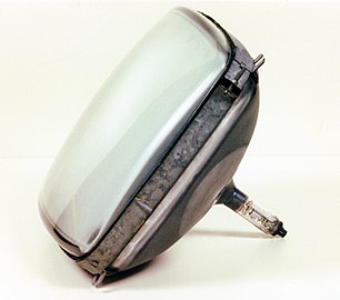 A monochrome CRT with 110° deflection
 -
 A monochrome CRT with 90° deflection


Size and weight
The size of the screen of a CRT is measured in two ways: the size of the screen or the face diagonal, and the viewable image size/area or viewable screen diagonal, which is the part of the screen with phosphor. The size of the screen is the viewable image size plus its edges which are not coated with phosphor.[209][200][210] The viewable image may be perfectly square or rectangular while the edges of the CRT are black and have a curvature or are flat (black stripe CRT),[158][177][211] or the edges of the image may follow the curvature of the edges of the CRT. [212][213] Black stripe CRTs were first made by Toshiba in 1972.[177]
Small CRTs below 3 inches were made for handheld televisions such as the MTV-1 and viewfinders in camcorders.[214][202][215][216][217]
Most of the weight of a CRT comes from the thick glass screen, which comprises 65% of the total weight of a CRT. The funnel and neck glass comprise the remaining 30% and 5% respectively. The glass in the funnel is thinner than on the screen.[7][6] Chemically or thermally tempered glass may be used to reduce the weight of the CRT glass.[218][219][220]
Anode
The outer conductive coating is connected to ground while the inner conductive coating is connected using the anode button/cap through a series of capacitors and diodes (a Cockcroft–Walton generator) to the high voltage flyback transformer; the inner coating is the anode of the CRT,[221] which together with an electrode in the electron gun, is also known as the final anode.[222][223] The inner coating is connected to the electrode using springs. The electrode forms part of a bipotential lens.[223][224] The capacitors and diodes serve as a voltage multiplier for the current delivered by the flyback.
For the inner coating, monochrome CRTs use aluminum while color CRTs use aquadag;[161] Some CRTs may use iron oxide on the inside.[7] On the outside most CRTs use aquadag.[225] Aquadag is an electrically conductive paint. In color CRTs the aquadag is sprayed onto the interior of the funnel[226][161] whereas historically aquadag was painted into the interior of monochrome CRTs.[17]
The anode is used to accelerate the electrons towards the screen and also collects the secondary electrons that are emitted by the phosphor particles in the vacuum of the CRT.[227][228][229][230][17]
The anode cap connection in modern CRTs must be able to handle up to 55-60kv depending on the size and brightness of the CRT.[231][186] It consists of a metal clip that expands on the inside of an anode button that is embedded on the funnel glass of the CRT.[232][233] The connection is insulated by a silicone suction cup, possibly also using silicone grease to prevent corona discharge.[234][235]
The anode button must be specially shaped to establish a hermetic seal between the button and funnel. X-rays may leak through the anode button, although that may not the case in newer CRTs starting from the late 1970s to early 1980s, thanks to a new button and clip design.[186] The button may consist of a set of 3 nested cups, with the outermost cup being made of a Nickel-Chromium-Iron alloy containing 40 to 49% of Nickel and 3 to 6% of Chromium to make the button easy to fuse to the funnel glass, with a first inner cup made of thick inexpensive iron to shield against x-rays, and with the second innermost cup also being made of iron or any other electrically conductive metal to connect to the clip. The cups must be heat resistant enough and have similar thermal expansion coefficients similar to that of the funnel glass to withstand being fused to the funnel glass. The inner side of the button is connected to the inner conductive coating of the CRT.[228] The anode button may be attached to the funnel while its being pressed into shape in a mold.[236][237][186] Alternatively, the x-ray shielding may instead be built into the clip.[238]
The flyback transformer is also known as an IHVT (Integrated High Voltage Transformer) if it includes a voltage multiplier. The flyback uses a ceramic or powdered iron core to enable efficient operation at high frequencies. The flyback contains one primary and many secondary windings that provide several different voltages. The main secondary winding supplies the voltage multiplier with voltage pulses to ultimately supply the CRT with the high anode voltage it uses, while the remaining windings supply the CRT's filament voltage, keying pulses, focus voltage and voltages derived from the scan raster. When the transformer is turned off, the flyback's magnetic field quickly collapses which induces high voltage in its windings. The speed at which the magnetic field collapses determines the voltage that is induced, so the voltage increases alongside its speed. A capacitor (Retrace Timing Capacitor) or series of capacitors (to provide redundancy) is used to slow the collapse of the magnetic field.[239][240]
The design of the high voltage power supply in a product using a CRT has an influence in the amount of x-rays emitted by the CRT. The amount of emitted x-rays increases with both higher voltages and currents. If the product such as a TV set uses an unregulated high voltage power supply, meaning that anode and focus voltage go down with increasing electron current when displaying a bright image, the amount of emitted x-rays is as its highest when the CRT is displaying a moderately bright images, since when displaying dark or bright images, the higher anode voltage counteracts the lower electron beam current and viceversa respectively. The high voltage regulator and rectifier vacuum tubes in some old CRT TV sets may also emit x-rays.[241]
Electron gun
The electron gun emits the electrons that ultimately hit the phosphors on the screen of the CRT. The electron gun contains a heater, which heats a cathode, which generates electrons that, using grids, are focused and ultimately accelerated into the screen of the CRT. The acceleration occurs in conjunction with the inner aluminum or aquadag coating of the CRT. The electron gun is positioned so that it aims at the center of the screen.[223] It is inside the neck of the CRT, and it is held together and mounted to the neck using glass beads or glass support rods, which are the glass strips on the electron gun.[17][223][242] The electron gun is made separately and then placed inside the neck through a process called "winding", or sealing.[57][243][244][245][246][125] The electron gun has a glass wafer that is fused to the neck of the CRT. The connections to the electron gun penetrate the glass wafer.[244][247] Once the electron gun is inside the neck, its metal parts (grids) are arced between each other using high voltage to smooth any rough edges in a process called spot knocking, to prevent the rough edges in the grids from generating secondary electrons.[248][249][250]
Construction and method of operation in a CRT
It has a hot cathode that is heated by a tungsten filament heating element; the heater may draw 0.5 to 2A of current depending on the CRT. The voltage applied to the heater can affect the life of the CRT.[251][252] Heating the cathode energizes the electrons in it, aiding electron emission,[253] while at the same time current is supplied to the cathode; typically anywhere from 140 mA at 1.5 V to 600 mA at 6.3 V.[254] The cathode creates an electron cloud (emits electrons) whose electrons are extracted, accelerated and focused into an electron beam.[17] Color CRTs have three cathodes: one for red, green and blue. The heater sits inside the cathode but doesn't touch it; the cathode has its own separate electrical connection. The cathode is coated onto a piece of nickel which provides the electrical connection and structural support.[221][255][256][257]
There are several shortcircuits that can occur in a CRT electron gun. One is a heater-to-cathode short, that causes the cathode to permanentely emit electrons which may cause an image with a bright red, green or blue tint with retrace lines, depending on the cathode (s) affected. Alternatively, the cathode may short to the control grid, possibly causing similar effects, or, the control grid and screen grid (G2)[258] can short causing a very dark image or no image at all. The cathode may be surrounded by a shield to prevent sputtering.[259][260]
The cathode is made of barium oxide[261][185] that must be activated by heating to enable it to release electrons. Activation is necessary because barium oxide is not stable in air, so it is applied to the cathode as barium carbonate, which cannot emit electrons. Activation heats the barium carbonate to decompose it into barium oxide and carbon dioxide while forming a thin layer of metallic barium on the cathode.[262][261] Activation occurs during evacuation of (at the same time a vacuum is formed in) the CRT. After activation the oxide can become damaged by several common gases such as water vapor, carbon dioxide, and oxygen.[263] Alternatively, barium strontium calcium carbonate may be used instead of barium carbonate, yielding barium, strontium and calcium oxides after activation.[264][17] During operation, the barium oxide is heated to 800-1000°C, at which point it starts shedding electrons.[265][185][253]
Since it is a hot cathode, it is prone to cathode poisoning, which is the formation of a positive ion layer that prevents the cathode from emitting electrons, reducing image brightness significantly or completely and causing focus and intensity to be affected by the frequency of the video signal preventing detailed images from being displayed by the CRT. The positive ions come from leftover air molecules inside the CRT or from the cathode itself[17] that react over time with the surface of the hot cathode.[266][260] Reducing metals such as manganese, zirconium, magnesium, aluminum or titanium may be added to the piece of nickel to lengthen the life of the cathode, as during activation, the reducing metals diffuse into the barium oxide, improving its lifespan, especially at high electron beam currents.[267] In color CRTs with red, green and blue cathodes, one or more cathodes may be affected independently of the others, causing total or partial loss of one or more colors.[260] CRTs can wear or burn out due to cathode poisoning. Cathode poisoning is accelerated by increased cathode current (overdriving).[268] In color CRTs, since there are three cathodes, one for red, green and blue, a single or more poisoned cathode may cause the partial or complete loss of one or more colors, tinting the image.[260] The layer may also act as a capacitor in series with the cathode, inducing thermal lag. The cathode may instead be made of scandium oxide or incorporate it as a dopant, to delay cathode poisoning, extending the life of the cathode by up to 15%.[269][185][270]
The amount of electrons generated by the cathodes is related to their surface area. A cathode with more surface area creates more electrons, in a larger electron cloud, which makes focusing the electron cloud into an electron beam more difficult.[268] Normally, only a part of the cathode emits electrons unless the CRT displays images with parts that are at full image brightness; only the parts at full brightness cause all of the cathode to emit electrons. The area of the cathode that emits electrons grows from the center outwards as brightness increases, so cathode wear may be uneven. When only the center of the cathode is worn, the CRT may light brightly those parts of images that have full image brightness but not show darker parts of images at all, in such a case the CRT displays a poor gamma characteristic.[260]
The second (screen) grid of the gun (G2) accelerates the electrons towards the screen using several hundred DC volts. A negative current[271] is applied to the first (control) grid (G1) to converge the electron beam. G1 in practice is a Wehnelt cylinder.[254][272] The brightness of the screen is not controlled by varying the anode voltage nor the electron beam current (they are never varied) despite them having an influence on image brightness, rather image brightness is controlled by varying the difference in voltage between the cathode and the G1 control grid. A third grid (G3) electrostatically focuses the electron beam before it is deflected and accelerated by the anode voltage onto the screen.[273] Electrostatic focusing of the electron beam may be accomplished using an Einzel lens energized at up to 600 volts.[274][262] Before electrostatic focusing, focusing the electron beam required a large, heavy and complex mechanical focusing system placed outside the electron gun.[198]
However, electrostatic focusing cannot be accomplshed near the final anode of the CRT due to its high voltage in the dozens of Kilovolts, so a high voltage (~600[275] to 8000 volt) electrode, together with an electrode at the final anode voltage of the CRT, may be used for focusing instead. Such an arrangement is called a bipotential lens, which also offers higher performance than an Einzel lens, or, focusing may be accomplished using a magnetic focusing coil together with a high anode voltage of dozens of kilovolts. However, magnetic focusing is expensive to implement, so it is rarely used in practice.[221][262][276][277] Some CRTs may use two grids and lenses to focus the electron beam.[269] The focus voltage is generated in the flyback using a subset of the flyback's high voltage winding in conjuntion with a resistive voltage divider. The focus electrode is connected alongside the other connections that are in the neck of the CRT.[278]
There is a voltage called cutoff voltage which is the voltage that creates black on the screen since it causes the image on the screen created by the electron beam to dissappear, the voltage is applied to G1. In a color CRT with three guns, the guns have different cutoff voltages. Many CRTs share grid G1 and G2 across all three guns, increasing image brightness and simplifying adjustment since on such CRTs there is a single cutoff voltage for all three guns (since G1 is shared across all guns).[223] but placing additional stress on the video amplifier used to feed video into the electron gun's cathodes, since the cutoff voltage becomes higher. Monochrome CRTs do not suffer from this problem. In monochrome CRTs video is fed to the gun by varying the voltage on the first control grid.[279][198]
During retracing of the electron beam, the preamplifier that feeds the video amplifier is disabled and the video amplifier is biased to a voltage higher than the cutoff voltage to prevent retrace lines from showing, or G1 can have a large negative voltage applied to it to prevent electrons from getting out of the cathode.[17] This is known as blanking. (see Vertical blanking interval and Horizontal blanking interval.) Incorrect biasing can lead to visible retrace lines on one or more colors, creating retrace lines that are tinted or white (for example, tinted red if the red color is affected, tinted magenta if the red and blue colors are affected, and white if all colors are affected).[280][281][282]Alternatively, the amplifier may be driven by a video processor that also introduces an OSD (On Screen Display) into the video stream that is fed into the amplifier, using a fast blanking signal.[283] TV sets and computer monitors that incorporate CRTs need a DC restoration circuit to provide a video signal to the CRT with a DC component, restoring the original brightness of different parts of the image.[284]
The electron beam may be affected by the earth's magnetic field, causing it to normally enter the focusing lens off-center; this can be corrected using astigmation controls. Astigmation controls are both magnetic and electronic (dynamic); magnetic does most of the work while electronic is used for fine adjustments.[285] The end of the electron gun has a glass disk, the edges of which are fused with the edge of the neck of the CRT, possibly using frit;[286] the metal leads that connect the electron gun to the outside pass through the disk.[287]
Some electron guns have a quadrupole lens with dynamic focus to alter the shape and adjust the focus of the electron beam, varying the focus voltage depending on the position of the electron beam to maintain image sharpness across the entire screen, specially at the corners.[157][288][289][290][291] They may also have a bleeder resistor to derive voltages for the grids from the final anode voltage.[292][293][294]
After the CRTs were manufactured, they were aged to allow cathode emission to stabilize.[295][296]
The electron guns in color CRTs are driven by a video amplifier which takes a signal per color channel and amplifies it to 40-170v per channel, to be fed into the electron gun's cathodes;[282] each electron gun has its own channel (one per color) and all channels may be driven by the same amplifier, which internally has three separate channels.[297] The amplifier's capabilities limit the resolution and contrast ratio of the CRT, as the amplifier needs to provide high bandwidth and voltage variations at the same time; higher resolutions and contrast ratios need higher bandwidths and voltage variations to switch quickly between black and white, respectively. 30Mhz of bandwidth can usually provide 720p or 1080i resolution, while 20Mhz usually provides around 600 (horizontal, from top to bottom) lines of resolution, for example.[298][282] The difference in voltage between the cathode and the control grid is what modulates the electron beam, modulating its current and thus the brightness of the image.[260] The phosphors used in color CRTs produce different amounts of light for a given amount of energy, so to produce white on a color CRT, all three guns must output differing amounts of energy. The gun that outputs the most energy is the red gun since the red phosphor emits the least amount of light. [282]
Gamma
CRTs have a pronounced triode characteristic, which results in significant gamma (a nonlinear relationship in an electron gun between applied video voltage and beam intensity).[299]
Deflection
There are two types of deflection: magnetic and electrostatic. Magnetic is usually used in TVs and monitors as it allows for higher deflection angles (and hence shallower CRTs) and deflection power (which allows for higher electron beam current and hence brighter images)[300] while avoiding the need for high voltages for deflection of up to 2000 volts,[207][301] while oscilloscopes often use electrostatic deflection since the raw waveforms captured by the oscilloscope can be applied directly (after amplification) to the vertical electrostatic deflection plates inside the CRT.[302]
Magnetic deflection
Those that use magnetic deflection may use a yoke that has two pairs of deflection coils; one pair for vertical, and another for horizontal deflection.[303] The yoke can be bonded (be integral) or removable. Those that were bonded used glue[304] or a plastic[305] to bond the yoke to the area between the neck and the funnel of the CRT while those with removable yokes are clamped.[306][163] The yoke generates heat whose removal is essential since the conductivity of glass goes up with increasing temperature, the glass needs to be insulating for the CRT to remain usable as a capacitor. The temperature of the glass below the yoke is thus checked during the design of a new yoke.[185] The yoke contains the deflection and convergence coils with a ferrite core to reduce loss of magnetic force[307][303] as well as the magnetized rings used to align or adjust the electron beams in color CRTs (The color purity and convergence rings, for example)[308] and monochrome CRTs.[309][310] The yoke may be connected using a connector, the order in which the deflection coils of the yoke are connected determines the orientation of the image displayed by the CRT.[204] The deflection coils may be held in place using polyurethane glue. [304]
The deflection coils are driven by sawtooth signals[311][312][282] that may be delivered through VGA as horizontal and vertical sync signals.[313] A CRT needs two deflection circuits: a horizontal and a vertical circuit, which are similar except that the horizontal circuit runs at a much higher frequency (a Horizontal scan rate) of 15 to 240kHz depending on the refresh rate of the CRT and the number of horizontal lines to be drawn (the vertical resolution of the CRT). The higher frequency makes it more susceptible to interference, so an automatic frequency control (AFC) circuit may be used to lock the phase of the horizontal deflection signal to that of a sync signal, to prevent the image from becoming distorted diagonally. The vertical frequency varies according to the refresh rate of the CRT. So a CRT with a 60Hz refresh rate has a vertical deflection circuit running at 60Hz. The horizontal and vertical deflection signals may be generated using two circuits that work differently; the horizontal deflection signal may be generated using a voltage controlled oscillator (VCO) while the vertical signal may be generated using a triggered relaxation oscillator. In many TVs, the frequencies at which the deflection coils run is in part determined by the inductance value of the coils.[314][282] CRTs had differing deflection angles; the higher the deflection angle, the shallower the CRT[315] for a given screen size, but at the cost of more deflection power and lower optical performance.[185][316]
Higher deflection power means more current[317] is sent to the deflection coils to bend the electron beam at a higher angle,[157] which in turn may generate more heat or require electronics that can handle the increased power.[316] Heat is generated due to resistive and core losses.[318] The deflection power is measured in mA per inch.[282] The vertical deflection coils may require approximately 24 volts while the horizontal deflection coils require appox. 120 volts to operate.[301]
The deflection coils are driven by deflection amplifiers.[319] The horizontal deflection coils may also be driven in part by the horizontal output stage of a TV set. The stage contains a capacitor that is in series with the horizontal deflection coils that performs several functions, among them are: shaping the sawtooth deflection signal to match the curvature of the CRT and centering the image by preventing a DC bias from developing on the coil. At the beggining of retrace, the magnetic field of the coil collapses, causing the electron beam to return to the center of the screen, while at the same time the coil returns energy into capacitors, the energy of which is then used to force the electron beam to go to the left of the screen. [239]
Due to the high frequency at which the horizontal deflection coils operate, the energy in the deflection coils must be recycled to reduce heat dissipation. Recycling is done by transferring the energy in the deflection coils' magnetic field to a set of capacitors.[239] The voltage on the horizontal deflection coils is negative when the electron beam is on the left side of the screen and positive when the electron beam is on the right side of the screen. The energy required for deflection is dependent on the energy of the electrons. [320] Higher energy (voltage and/or current) electron beams need more energy to be deflected,[178] and are used to achieve higher image brightness.[321][322][231]
Electrostatic deflection
Mostly used in oscilloscopes. Deflection is carried out by applying a voltage across two pairs of plates, one for horizontal, and the other for vertical deflection. The electron beam is steered by varying the voltage difference across plates in a pair; For example, applying a voltage of 200 volts to the upper plate of the vertical deflection pair, while keeping the voltage in the bottom plate at 0 volts, will cause the electron beam to be deflected towards the upper part of the screen; increasing the voltage in the upper plate while keeping the bottom plate at 0 will cause the electron beam to be deflected to a higher point in the screen (will cause the beam to be deflected at a higher deflection angle). The same applies with the horizontal deflection plates. Increasing the length and proximity between plates in a pair can also increase the deflection angle.[323]
Burn-in
Burn-in is when images are physically "burned" into the screen of the CRT; this occurs due to degradation of the phosphors due to prolonged electron bombardment of the phosphors, and happens when a fixed image or logo is left for too long on the screen, causing it to appear as a "ghost" image or, in severe cases, also when the CRT is off. To counter this, screensavers were used in computers to minimize burn-in.[324] Burn-in is not exclusive to CRTs, as it also happens to plasma displays and OLED displays.
Evacuation
CRTs are evacuated or exhausted (a vacuum is formed) inside an oven at approx. 375-475°C, in a process called baking or bake-out.[325] The evacuation process also outgasses any materials inside the CRT, while decomposing others such as the polyvinyl alcohol used in the phosphors.[326] The heating and cooling are done gradually to avoid inducing stress, stiffening and possibly cracking the glass; the oven heats the gases inside the CRT, increasing the speed of the gas molecules which increases the chances of them getting drawn out by the vacuum pump. The temperature of the CRT is kept to below that of the oven, and the oven starts to cool just after the CRT reaches 400°C, or, the CRT was kept at a temperature higher than 400°C for up to 15-55 minutes. The CRT was heated during or after evacuation, and the heat may have been used simultaneusly to melt the frit in the CRT, joining the screen and funnel.[327][328][329] The pump used is a turbomolecular pump or a diffusion pump.[330][331][332][333] Formerly mercury vacuum pumps were also used.[334][335] After baking, the CRT is disconnected ("sealed or tipped off") from the vacuum pump.[336][337][338] The getter is then fired using an RF (induction) coil. The getter is usually in the funnel or in the neck of the CRT.[339][340] The getter material which is often barium-based, catches any remaining gas particles as it evaporates due to heating induced by the RF coil (that may be combined with exothermic heating within the material); the vapor fills the CRT, trapping any gas molecules that it encounters and condenses on the inside of the CRT forming a layer that contains trapped gas molecules. Hydrogen may be present in the material to help distribute the barium vapor. The material is heated to temperatures above 1000°C, causing it to evaporate.[341][342][263] Partial loss of vacuum in a CRT can result in a hazy image, blue glowing in the neck of the CRT, flashovers, loss of cathode emission or focusing problems.[198] The vacuum inside of a CRT causes atmospheric pressure to exert (in a 27 inch CRT) a pressure of 5,800 pounds (2,600 kg) in total.[343]
Rebuilding
CRTs used to be rebuilt; repaired or refurbished. The rebuilding process included the dissassembly of the CRT, the dissasembly and repair or replacement of the electron gun(s), the removal and redeposition of phosphors and aquadag, etc. Rebuilding was popular until the 1960s because CRTs were expensive and wore out quickly, making repair worth it.[339] The last CRT rebuilder in the US closed in 2010,[344] and the last in Europe, RACS, which was located in France, closed in 2013.[345]
Reactivation
Also known as rejuvenation, the goal is to temporarily restore the brightness of a worn CRT. This is often done by carefully increasing the voltage on the cathode heater and the current and voltage on the control grids of the electron gun either manually[346] or using a special device called a CRT rejuvenator.[347][266] Some rejuvenators can also fix heater-to-cathode shorts by running a capacitive discharge through the short.[260]
Phosphors
Phosphors in CRTs emit secondary electrons due to them being inside the vacuum of the CRT. The secondary electrons are collected by the anode of the CRT.[230] Secondary electrons generated by phosphors need to be collected to prevent charges from developing in the screen, which would lead to reduced image brightness[17] since the charge would repel the electron beam.
The phosphors used in CRTs often contain rare earth metals,[348][349][324] replacing earlier dimmer phosphors. Early red and green phosphors contained Cadmium,[350] and some black and white CRT phosphors also contained beryllium powder,[41] although white phosphors containing cadmium, zinc, and magnesium with silver, copper or manganese as dopants were also used.[17] The rare earth phosphors used in CRTs are more efficient (produce more light) than earlier phosphors.[351] The phosphors adhere to the screen because of Van der Waals and electrostatic forces. Phosphors composed of smaller particles adhere more strongly to the screen. The phosphors together with the carbon used to prevent light bleeding (in color CRTs) can be easily removed by scratching.[182][352]
Several dozen types of phosphors were available for CRTs.[353] Phosphors were classified according to color, persistence, luminance rise and fall curves, color depending on anode voltage (for phosphors used in penetration CRTs), Intended use, chemical composition, safety, sensitivity to burn-in, and secondary emission properties.[354] Examples of rare earth phosphors are yittrium oxide for red and yittrium silicide for blue,[355] while examples of earlier phosphors are copper cadmium sulfide for red,
SMPTE-C phosphors have properties defined by the SMPTE-C standard, which defines a color space of the same name. The standard prioritizes accurate color reproduction, which was made difficult by the different phosphors and color spaces used in the NTSC and PAL color systems. PAL TV sets have subjectively better color reproduction due to the use of saturated green phosphors, which have relatively long decay times that are tolerated in PAL since there is more time in PAL for phosphors to decay, due to its lower framerate. SMPTE-C phosphors were used in professional video monitors.[356][357]
The phosphor coating on monochrome and color CRTs may have an aluminum coating on its rear side used to reflect light foward, provide protection against ions to prevent ion burn by negative ions on the phosphor, manage heat generated by electrons colliding against the phosphor,[358] prevent static build up that could repel electrons from the screen, form part of the anode and collect the secondary electrons generated by the phosphors in the screen after being hit by the electron beam, providing them with a return path.[359][360][185][361][362][358][17] The electron beam passes through the aluminum coating before hitting the phosphors on the screen; the aluminum attenuates the electron beam voltage by about 1kv.[363][17][354] A film or laquer may be applied to the phosphors to reduce the surface roughness of the surface formed by the phosphors to allow the aluminum coating to have a uniform surface and prevent it from touching the glass of the screen.[364][365] This is known as filming.[213] The laquer contains solvents that are later evaporated; the laquer may be chemically roughened to cause an aluminum coating with holes to be created to allow the solvents to escape.[365]
Phosphor persistence
Various phosphors are available depending upon the needs of the measurement or display application. The brightness, color, and persistence of the illumination depends upon the type of phosphor used on the CRT screen. Phosphors are available with persistences ranging from less than one microsecond to several seconds.[366] For visual observation of brief transient events, a long persistence phosphor may be desirable. For events which are fast and repetitive, or high frequency, a short-persistence phosphor is generally preferable.[367] The phosphor persistence must be low enough to avoid smearing or ghosting artifacts at high refresh rates.[157]
Limitations and workarounds
Blooming
Variations in anode voltage can lead to variations in brightness in parts or all of the image, in addition to blooming, shrinkage or the image getting zoomed in or out. Lower voltages lead to blooming and zooming in, while higher voltages do the opposite.[368][369] Some blooming (also known as doming)[370] is unavoidable, which can be seen as bright areas of an image that expand, distorting or pushing aside surrounding darker areas of the same image. Blooming occurs because bright areas have a higher electron beam current from the electron gun, making the beam wider and harder to focus, while also causing the shadow mask to expand due to thermal expansion caused by increased electron beam current, although it can also occur due to poor voltage regulation, in which case focus and anode voltage go down with increasing electron beam current.[241] Thermal expansion causes the shadow mask to expand by around 100 microns.[371][372][373][374][375]
Blooming also affects the focus of the electron beam, which is part of the reason why CRTs were curved. Another reason was to reduce the risk of an implosion.[56]
During normal operation the shadow mask is heated to around 80-90°C.[376] Bright areas of images heat the shadow mask more than dark areas, leading to uneven heating of the shadow mask and warping (blooming) due to thermal expansion caused by heating by increased electron beam current.[377][378] The shadow mask is usually made of steel but it can be made out of Invar[162] (a low-thermal expansion Nickel-Iron alloy) as it withstands two to three times more current than conventional masks without noticeable warping,[157][379][55] while making higher resolution CRTs easier to achieve.[380] Coatings that dissipate heat may be applied on the shadow mask to limit blooming[381][382] in a process called blackening.[383][384]
Bimetal springs may be used in CRTs used in TVs to compensate for warping that occurs as the electron beam heats the shadow mask, causing thermal expansion.[54] The shadow mask is installed to the screen using metal pieces[385] or a rail or frame[386][387][388] that is fused to the funnel or the screen glass respectively,[289] holding the shadow mask in tension to minimize warping (if the mask is flat, used in flat screen CRT computer monitors) and allowing for higher image brightness and contrast.
Aperture grille screens are brigher since they allow more electrons through, but they require support wires. They are also more resistant to warping.[157] Color CRTs need higher anode voltages than monochrome CRTs to achieve the same brightness since the shadow mask blocks most of the electron beam. Slot masks[42] and specially Aperture grilles don't block as many electrons resulting in a brighter image for a given anode voltage, but aperture gille CRTs are heavier.[162] Shadow masks block[389] 80-85%[377][376] of the electron beam while Aperture grilles allow more electrons to pass through.[390]
High voltage
Image brightness is related to the anode voltage and to the CRTs size, so higher voltages are needed for both larger screens[391] and higher image brightness. Image brightness is also controlled by the current of the electron beam.[268] Higher anode voltages and electron beam currents also mean higher amounts of x-rays and heat generation since the electrons have a higher speed and energy.[241] Leaded glass and special barium-strontium glass are used to block most x-ray emissions.
Size
Size is limited by anode voltage, as it would require a higher dielectric strength to prevent arcing (corona discharge) and the losses and ozone generation it causes. The weight of the CRT, which originates from the thick glass needed to safely sustain a vacuum, imposes a practical limit on the size of a CRT.[392] The 43-inch Sony PVM-4300 monitor weighs 440 pounds (200 kg).[393] Smaller CRTs weigh significantly less, as an example, 32-inch CRTs "only" weigh up to 163 pounds (74 kg). For comparison, a flat panel TV of the same size only weighs approx. 18 pounds (8.2 kg).[394]
Shadow masks become more difficult to make with increasing resolution and size.[380]
Limits imposed by deflection
At high deflection angles, resolutions and refresh rates (since higher resolutions and refresh rates require significantly higher frequencies to be applied to the horizontal deflection coils), the deflection yoke starts to produce large amounts of heat, due to the need to move the electron beam at a higher angle, which in turn requires exponentially larger amounts of power. As an example, to increase the deflection angle from 90 to 120°, power consumption of the yoke must also go up from 40 watts to 80 watts, and to increase it further from 120 to 150°, deflection power must again go up from 80 watts to 160 watts.[301] This normally makes CRTs that go beyond certain deflection angles, resolutions and refresh rates impractical, since the coils would generate too much heat due to resistance caused by the skin effect, surface and eddy current losses, as well as hysterisis losses in the magnetic core, melting the insulation in the coils of the CRT and/or possibly causing the glass underneath the coil to become conductive (as the electrical conductivity of glass decreases with increasing temperature). Some deflection yokes are designed to dissipate the heat that comes from their operation.[161][395][318][396][397][398] Higher deflection angles in color CRTs directly affect convergence at the corners of the screen which requires additional compensation circuitry to handle electron beam power and shape, leading to higher costs and power consumption.[399][400] Higher deflection angles allow a CRT of a given size to be slimmer, however they also impose more stress on the CRT envelope, specially on the panel, the seal between the panel and funnel and on the funnel. The funnel needs to be long enough to minimize stress, as a longer funnel can be better shaped to have lower stress.[145][401]
Types of CRT
CRTs were produced in two major categories, picture tubes and display tubes.[59] Picture tubes were used in TVs while display tubes were used in computer monitors. Display tubes had no overscan and were of higher resolution. Picture tube CRTs have overscan, meaning the edges of the image are not shown, This is deliberate to allow for adjustment variations between CRT TVs, preventing the ragged edges of the image from being shown on screen. The shadow mask may have special structures in place to reflect away the electrons that do not hit the screen due to overscan.[402][157] Color picture tubes used in TVs were also known as CPTs.[403]
Monochrome CRTs


If the CRT is a black and white (B&W or monochrome) CRT, there is a single electron gun in the neck and the funnel is coated on the inside with aluminum that has been applied by evaporation; the aluminum is evaporated in a vacuum and allowed to condense on the inside of the CRT. [213] Aluminum eliminates the need for ion traps, necessary to prevent ion burn on the phosphor, while also reflecting light generated by the phosphor towards the screen, managing heat and absorbing electrons providing a return path for them; previously funnels were coated on the inside with aquadag, used because it can be applied like paint;[203] the phosphors were left uncoated.[17] Aluminum started being applied to CRTs in the 1950s, coating the inside of the CRT including the phosphors, which also increased image brightness since the aluminum reflected light (that would otherwise be lost inside the CRT) towards the outside of the CRT.[17][404][405][406] In aluminized monochrome CRTs, Aquadag is used on the outside. There is a single aluminum coating covering the funnel and the screen.[213]
The screen, funnel and neck are fused together into a single envelope, possibly using lead enamel seals, a hole is made in the funnel onto which the anode cap is installed and the phosphor, aquadag and aluminum are applied afterwards.[57] Previously monochrome CRTs used ion traps that required magnets; the magnet was used to deflect the electrons away from the more difficult to deflect ions, letting the electrons through while letting the ions collide into a sheet of metal inside the electron gun.[407][198][358] Ion burn results in premature wear of the phosphor. Since ions are harder to deflect than electrons, ion burn leaves a black dot in the center of the screen.[198][358]
The interior aquadag or aluminum coating was the anode and served to accelerate the electrons towards the screen, collect them after hitting the screen while serving as a capacitor together with the outer aquadag coating. The screen has a single uniform phosphor coating and no shadow mask, technically having no resolution limit.[408][205][409]
Monochrome CRTs may use ring magnets to adjust the centering of the electron beam and magnets around the deflection yoke to adjust the geometry of the image.[310][410]
-
![Older monochrome CRT[411] without aluminum, only aquadag](//upload.wikimedia.org/wikipedia/commons/thumb/4/40/Osziroehre.jpg/430px-Osziroehre.jpg) Older monochrome CRT[411] without aluminum, only aquadag
Older monochrome CRT[411] without aluminum, only aquadag -
 The electron gun of a monochrome CRT
![Older monochrome CRT[411] without aluminum, only aquadag](/wiki/File:Osziroehre.jpg)

Color CRTs


Color CRTs use three different phosphors which emit red, green, and blue light respectively. They are packed together in stripes (as in aperture grille designs) or clusters called "triads" (as in shadow mask CRTs).[412][413]
Color CRTs have three electron guns, one for each primary color, (red, green and blue) arranged either in a straight line (in-line) or in an equilateral triangular configuration (the guns are usually constructed as a single unit).[223][303][414][415][416] (The triangular configuration is often called "delta-gun", based on its relation to the shape of the Greek letter delta Δ.) The arrangement of the phosphors is the same as that of the electron guns.[223][417] A grille or mask absorbs the electrons that would otherwise hit the wrong phosphor.[418]
A shadow mask tube uses a metal plate with tiny holes, placed so that the electron beam only illuminates the correct phosphors on the face of the tube;[412] blocking all other electrons.[146] Shadow masks that use slots instead of holes are known as slot masks.[419] The holes or slots are tapered[420][421] so that the electrons that strike the inside of any hole will be reflected back, if they are not absorbed (e.g. due to local charge accumulation), instead of bouncing through the hole to strike a random (wrong) spot on the screen. Another type of color CRT (Trinitron) uses an aperture grille of tensioned vertical wires to achieve the same result.[418] The shadow mask has a single hole for each triad.[223] The shadow mask is usually 1/2 inch behind the screen.[162]
Trinitron CRTs were different from other color CRTs in that they had a single electron gun with three cathodes, an aperture grille which lets more electrons through, increasing image brightness (since the aperture grille does not block as many electrons), and a vertically cylindrical, rather than a curved screen.[422]
The three electron guns are in the neck (except for Trinitrons) and the red, green and blue phosphors on the screen may be separated by a black grid or matrix (called black stripe by Toshiba).[56]
The funnel is coated with aquadag on both sides while the screen has a separate aluminum coating applied in a vacuum.[223][161] The aluminum coating protects the phosphor from ions, absorbs secondary electrons, providing them with a return path, preventing them from electrostatically charging the screen which would then repel electrons and reduce image brightness, reflects the light from the phosphors fowards and helps manage heat. It also serves as the anode of the CRT together with the inner aquadag coating. The inner coating is electrically connected to an electrode of the electron gun using springs, forming the final anode.[224][223] The outer aquadag coating is connected to ground, possibly using a series of springs or a harness that makes contact with the aquadag.[423][424]
Shadow mask
The shadow mask absorbs or reflects electrons that would otherwise strike the wrong phosphor dots,[409] causing color purity issues (discoloration of images), in other words, when set up correctly, the shadow mask helps ensure color purity.[223] When the electrons strike the shadow mask, they release their energy as heat and x-rays. If the electrons have too much energy due to an anode voltage that is too high for example, the shadow mask can warp due to the heat, which can also happen during the lehr baking at approx. 435°C of the frit seal between the faceplate and the funnel of the CRT.[389][425]
Shadow masks were replaced in TVs by slot masks in the 1970s, since slot masks let more electrons through, increasing image brightness. Shadow masks may be connected electrically to the anode of the CRT.[426][42][427][428] Trinitron used a single electron gun with three cathodes instead of three complete guns. CRT PC monitors usually use shadow masks, except for Sony's Trinitron, Mitsubishi's Diamondtron and NEC's Cromaclear; Trinitron and Diamondtron use aperture grilles while Cromaclear uses a slot mask. Some shadow mask CRTs have color phosphors that are smaller in diameter than the electron beams used to light them,[429] with the intention being to cover the entire phosphor, increasing image brightness.[430] Shadow masks may be pressed into a curved shape.[431][432][433]
Screen manufacture
Early color CRTs did not have a black matrix, which was introduced by Zenith in 1969, and Panasonic in 1970. [430][434][177] The black matrix eliminates light leaking from one phosphor to another since the black matrix isolates the phosphor dots from one another, so part of the electron beam touches the black matrix. This is also made necessary by warping of the shadow mask.[56][429] Light bleeding may still occur due to stray electrons stricking wrong phosphor dots. At high resolutions and refresh rates, phosphors only receive a very small amount of energy, limiting image brightness.[380]
Several methods were used to create the black matrix; one method coated the screen in photoresist such as dichromate-sensitized polyvinyl alcohol photoresist which was then dried and exposed; the unexposed areas were removed and the entire screen was coated in colloidal graphite to create a carbon film, and then hydrogen peroxide was used to remove the remaining photoresist alongside the carbon that was on top of it, creating holes that in turn created the black matrix. The photoresist had to be of the correct thickness to ensure sufficient adhesion to the screen, while the exposure step had to be controlled to avoid holes that were too small or large with ragged edges caused by light diffraction, ulitimately limiting the maximum resolution of large color CRTs.[429] The holes were then filled with phosphor using the method described above. Another method used phosphors suspended in a aromatic diazonium salt that adhered to the screen when exposed to light; the phosphors were applied, then exposed to cause them to adhere to the screen, repeating the process once for each color. Then carbon was applied to the remaining areas of the screen while exposing the entire screen to light to create the black matrix, and a fixing process using an aqueous polymer solution was applied to the screen to make the phosphors and black matrix resistant to water. [434] Black chromium may be used instead of carbon in the black matrix.[429] Other methods were also used.[435][436][437][438]
The phosphors are applied using photolithography. The inner side of the screen is coated with phosphor particles suspended in PVA photoresist slurry,[439][440] which is then dried using infrared light,[441] exposed, and developed. The exposure is done using a "lighthouse" that uses an ultraviolet light source with a corrector lens to allow the CRT to achieve color purity. Removable shadow masks with spring-loaded clips are used as photomasks. The process is repeated with all colors. Usually the green phosphor is the first to be applied.[223][442][443][444] After phosphor application, the screen is baked to eliminate any organic chemicals (such as the PVA that was used to deposit the phosphor) that may remain on the screen.[434][445] Alternatively, the phosphors may be applied in a vacuum chamber by evaporating them and allowing them to condense on the screen, creating a very uniform coating.[269] Early color CRTs had their phosphors deposited using silkscreen printing.[34] Phosphors may have color filters over them (facing the viewer), contain pigment of the color emitted by the phosphor,[446][349] or be encapsulated in color filters to improve color purity and reproduction while reducing glare.[443][428] Poor exposure due to insufficient light leads to poor phosphor adhesion to the screen, which limits the maximum resolution of a CRT, as the smaller phosphor dots required for higher resolutions cannot receive as much light due to their smaller size.[447]
After the screen is coated with phosphor and aluminum and the shadow mask installed onto it the screen is bonded to the funnel using a glass frit that may contain 65 to 88% of lead oxide by weight. The lead oxide is necessary for the glass frit to have a low melting temperature. Boron oxide (III) may also present to stabilize the frit, with alumina powder as filler powder to control the thermal expansion of the frit.[448][191][7] The frit may be applied as a paste consisting of frit particles suspended in amyl acetate or in a polymer with a alkyl methacrylate monomer together with an organic solvent to dissolve the polymer and monomer.[449][450] The CRT is then baked in an oven in what is called a Lehr bake, to cure the frit, sealing the funnel and screen together. The frit contains a large quantity of lead, causing color CRTs to contain more lead than their monochrome counterparts. Monochrome CRTs on the other hand do not require frit; the funnel can be fused directly to the glass[146] by melting and joining the edges of the funnel and screen using gas flames. Frit is used in color CRTs to prevent deformation of the shadow mask and screen during the fusing process. The edges of the screen and funnel of the CRT are never melted.[223] A primer may be applied on the edges of the funnel and screen before the frit paste is applied to improve adhesion.[451] The Lehr bake consists of several sucessive steps that heat and then cool the CRT gradually until it reaches a temperature of 435 to 475°C[449] (other sources may state different temperatures, such as 440°C)[452] After the lehr bake, the CRT is flushed with air or nitrogen to remove contaminants, the electron gun is inserted and sealed into the neck of the CRT, and a vacuum is formed on the CRT.[453][245]
Convergence and purity in color CRTs
Due to limitations in the dimensional precision with which CRTs can be manufactured economically, it has not been practically possible to build color CRTs in which three electron beams could be aligned to hit phosphors of respective color in acceptable coordination, solely on the basis of the geometric configuration of the electron gun axes and gun aperture positions, shadow mask apertures, etc. The shadow mask ensures that one beam will only hit spots of certain colors of phosphors, but minute variations in physical alignment of the internal parts among individual CRTs will cause variations in the exact alignment of the beams through the shadow mask, allowing some electrons from, for example, the red beam to hit, say, blue phosphors, unless some individual compensation is made for the variance among individual tubes.
Color convergence and color purity are two aspects of this single problem. Firstly, for correct color rendering it is necessary that regardless of where the beams are deflected on the screen, all three hit the same spot (and nominally pass through the same hole or slot) on the shadow mask.[clarification needed] This is called convergence.[454] More specifically, the convergence at the center of the screen (with no deflection field applied by the yoke) is called static convergence, and the convergence over the rest of the screen area (specially at the edges and corners) is called dynamic convergence.[163] The beams may converge at the center of the screen and yet stray from each other as they are deflected toward the edges; such a CRT would be said to have good static convergence but poor dynamic convergence. Secondly, each beam must only strike the phosphors of the color it is intended to strike and no others. This is called purity. Like convergence, there is static purity and dynamic purity, with the same meanings of "static" and "dynamic" as for convergence. Convergence and purity are distinct parameters; a CRT could have good purity but poor convergence, or vice versa. Poor convergence causes color "shadows" or "ghosts" along displayed edges and contours, as if the image on the screen were intaglio printed with poor registration. Poor purity causes objects on the screen to appear off-color while their edges remain sharp. Purity and convergence problems can occur at the same time, in the same or different areas of the screen or both over the whole screen, and either uniformly or to greater or lesser degrees over different parts of the screen.
The solution to the static convergence and purity problems is a set of color alignment ring magnets installed around the neck of the CRT.[455] These movable weak permanent magnets are usually mounted on the back end of the deflection yoke assembly and are set at the factory to compensate for any static purity and convergence errors that are intrinsic to the unadjusted tube. Typically there are two or three pairs of two magnets in the form of rings made of plastic impregnated with a magnetic material, with their magnetic fields parallel to the planes of the magnets, which are perpendicular to the electron gun axes. Often, one ring has two poles, another has 4, and the remaining ring has 6 poles.[456] Each pair of magnetic rings forms a single effective magnet whose field vector can be fully and freely adjusted (in both direction and magnitude). By rotating a pair of magnets relative to each other, their relative field alignment can be varied, adjusting the effective field strength of the pair. (As they rotate relative to each other, each magnet's field can be considered to have two opposing components at right angles, and these four components [two each for two magnets] form two pairs, one pair reinforcing each other and the other pair opposing and canceling each other. Rotating away from alignment, the magnets' mutually reinforcing field components decrease as they are traded for increasing opposed, mutually cancelling components.) By rotating a pair of magnets together, preserving the relative angle between them, the direction of their collective magnetic field can be varied. Overall, adjusting all of the convergence/purity magnets allows a finely tuned slight electron beam deflection or lateral offset to be applied, which compensates for minor static convergence and purity errors intrinsic to the uncalibrated tube. Once set, these magnets are usually glued in place, but normally they can be freed and readjusted in the field (e.g. by a TV repair shop) if necessary.
On some CRTs, additional fixed adjustable magnets are added for dynamic convergence or dynamic purity at specific points on the screen, typically near the corners or edges. Further adjustment of dynamic convergence and purity typically cannot be done passively, but requires active compensation circuits, one to correct convergence horizontally and another to correct it vertically. The deflection yoke contains convergence coils, a set of two per color, wound on the same core, to which the convergence signals are applied. That means 6 convergence coils in groups of 3, with 2 coils per group, with one coil for horizontal convergence correction and another for vertical convergence correction, with each group sharing a core. The groups are separated 120° from one another. Dynamic convergence is necessary because the front of the CRT and the shadow mask aren't spherical, compensating for electron beam defocusing and astigmatism. The fact that the CRT screen isn't spherical[457] leads to geometry problems which may corrected using a circuit.[458] The signals used for convergence are parabolic waveforms derived from three signals coming from a vertical output circuit. The parabolic signal is fed into the convergence coils, while the other two are sawtooth signals that, when mixed with the parabolic signals, create the necessary signal for convergence. A resistor and diode are used to lock the convergence signal to the center of the screen to prevent it from being affected by the static convergence. The horizontal and vertical convergence circuits are similar. Each circuit has two resonators, one usually tuned to 15,625Hz and the other to 31,250Hz, which set the frequency of the signal sent to the convergence coils.[459] Dynamic convergence may be accomplished using electrostatic quadrupole fields in the electron gun.[460] Dynamic convergence means that the electron beam does not travel in a perfectly straight line between the deflection coils and the screen, since the convergence coils cause it to become curved to conform to the screen.
The convergence signal may instead be a sawtooth signal with a slight sine wave appearance, the sine wave part is created using a capacitor in series with each deflection coil. In this case, the convergence signal is used to drive the deflection coils. The sine wave part of the signal causes the electron beam to move more slowly near the edges of the screen. The capacitors used to create the convergence signal are known as the s-capacitors. This type of convergence is necessary due to the high deflection angles and flat screens of many CRT computer monitors. The value of the s-capacitors must be chosen based on the scan rate of the CRT, so multi-syncing monitors must have different sets of s-capacitors, one for each refresh rate. [157]
Dynamic convergence may instead be accomplished in some CRTs using only the ring magnets, magnets glued to the CRT, and by varying the position of the deflection yoke, whose position may be maintained using set screws, a clamp and rubber wedges.[163][461] 90° deflection angle CRTs may use "self-convergence" without dynamic convergence, which together with the in-line triad arrangement, eliminates the need for separate convergence coils and related circuitry, reducing costs. complexity and CRT depth by 10 milimeters. Self-convergence works by means of "nonuniform" magnetic fields. Dynamic convergence is necessary in 110° deflection angle CRTs, and quadrupole windings on the deflection yoke at a certain frequency may also be used for dynamic convergence.[462]
Dynamic color convergence and purity are one of the main reasons why until late in their history, CRTs were long-necked (deep) and had biaxially curved faces; these geometric design characteristics are necessary for intrinsic passive dynamic color convergence and purity. Only starting around the 1990s did sophisticated active dynamic convergence compensation circuits become available that made short-necked and flat-faced CRTs workable. These active compensation circuits use the deflection yoke to finely adjust beam deflection according to the beam target location. The same techniques (and major circuit components) also make possible the adjustment of display image rotation, skew, and other complex raster geometry parameters through electronics under user control.[157]
The guns are aligned with one another (converged) using convergence rings placed right outside the neck; there is one ring per gun. The rings have north and south poles. There are 4 sets of rings, one to adjust RGB convergence, a second to adjust Red and Blue convergence, a third to adjust vertical raster shift, and a fourth to adjust purity. The vertical raster shift adjusts the straightness of the scan line. CRTs may also employ dynamic convergence circuits, which ensure correct convergence at the edges of the CRT. Permalloy magnets may also be used to correct the convergence at the edges. Convergence is carried out with the help of a crosshatch (grid) pattern.[463][464] Other CRTs may instead use magnets that are pushed in and out instead of rings.[424]
In early color CRTs, the holes in the shadow mask became progressively smaller as they extended outwards from the center of the screen, to aid in convergence.[430]
Magnetic shielding and degaussing


If the shadow mask or aperture grille becomes magnetized, its magnetic field alters the paths of the electron beams. This causes errors of "color purity" as the electrons no longer follow only their intended paths, and some will hit some phosphors of colors other than the one intended. For example, some electrons from the red beam may hit blue or green phosphors, imposing a magenta or yellow tint to parts of the image that are supposed to be pure red. (This effect is localized to a specific area of the screen if the magnetization is localized.) Therefore, it is important that the shadow mask or aperture grille not be magnetized. The earth's magnetic field may have an effect on the color purity of the CRT.[463] Because of this, some CRTs have external magnetic shields over their funnels. The magnetic shield may be made of soft iron or mild steel and contain a degaussing coil.[465] The magnetic shield and shadow mask may be permanentely magnetized by the earth's magnetic field, adversely affecting color purity when the CRT is moved. This problem is solved with a built-in degaussing coil, found in many TVs and computer monitors. Degaussing may be automatic, ocurring whenever the CRT is turned on.[466][223] The magnetic shield may also be internal, being on the inside of the funnel of the CRT.[467][468][157][469][470][471]
Most color CRT displays, i.e. television sets and computer monitors, each have a built-in degaussing (demagnetizing) circuit, the primary component of which is a degaussing coil which is mounted around the perimeter of the CRT face inside the bezel. Upon power-up of the CRT display, the degaussing circuit produces a brief, alternating current through the degaussing coil which smoothly decays in strength (fades out) to zero over a period of a few seconds, producing a decaying alternating magnetic field from the coil. This degaussing field is strong enough to remove shadow mask magnetization in most cases, maintaining color purity.[472][473] In unusual cases of strong magnetization where the internal degaussing field is not sufficient, the shadow mask may be degaussed externally with a stronger portable degausser or demagnetizer. However, an excessively strong magnetic field, whether alternating or constant, may mechanically deform (bend) the shadow mask, causing a permanent color distortion on the display which looks very similar to a magnetization effect.
The degaussing circuit is often built of a thermo-electric (not electronic) device containing a small ceramic heating element and a positive thermal coefficient (PTC) resistor, connected directly to the switched AC power line with the resistor in series with the degaussing coil. When the power is switched on, the heating element heats the PTC resistor, increasing its resistance to a point where degaussing current is minimal, but not actually zero. In older CRT displays, this low-level current (which produces no significant degaussing field) is sustained along with the action of the heating element as long as the display remains switched on. To repeat a degaussing cycle, the CRT display must be switched off and left off for at least several seconds to reset the degaussing circuit by allowing the PTC resistor to cool to the ambient temperature; switching the display-off and immediately back on will result in a weak degaussing cycle or effectively no degaussing cycle.
This simple design is effective and cheap to build, but it wastes some power continuously. Later models, especially Energy Star rated ones, use a relay to switch the entire degaussing circuit on and off, so that the degaussing circuit uses energy only when it is functionally active and needed. The relay design also enables degaussing on user demand through the unit's front panel controls, without switching the unit off and on again. This relay can often be heard clicking off at the end of the degaussing cycle a few seconds after the monitor is turned on, and on and off during a manually initiated degaussing cycle.
CRT resolution
Dot pitch defines the maximum resolution of the display, assuming delta-gun CRTs. In these, as the scanned resolution approaches the dot pitch resolution, moiré appears, as the detail being displayed is finer than what the shadow mask can render.[474] Aperture grille monitors do not suffer from vertical moiré; however, because their phosphor stripes have no vertical detail. In smaller CRTs, these strips maintain position by themselves, but larger aperture-grille CRTs require one or two crosswise (horizontal) support strips; one for smaller CRTs, and two for larger ones. The support wires block electrons, causing the wires to be visible.[475] In aperture grille CRTs, dot pitch is replaced by stripe pitch. Hitachi developed the Enhanced Dot Pitch (EDP) shadow mask, which uses oval holes instead of circular ones, with respecitve oval phosphor dots.[428] Moire is reduced in Shadow mask CRTs by arranging the holes in the shadow mask in a honeycomb-like pattern.[157]
Other types of CRT
Projection CRTs
Projection CRTs were used in CRT projectors and CRT rear-projection televisions and are usually small being 7 to 9 inches across,[298] have a phosphor that generates either red, green or blue light, thus making them monochrome CRTs,[476] and are similar in construction to monochrome CRTs. Larger projection CRTs in general lasted longer, and were able to provide higher brightness levels and resolution, but were also more expensive.[477][478] Projection CRTs have an unusually high anode voltage for their size (such as 25 to 27kv for a 5 to 7-inch projection CRT)[479][480] and a specially made tungsten barium cathode (instead of the pure barium oxide normally used) that consists of barium atoms embedded in 20% porous tungsten or barium and calcium aluminates or barium, calcium and aluminum oxides coated on porous tungsten; the barium diffuses through the tungsten to emit electrons.[481] The special cathode can deliver 2mA of current instead of the 0.3mA of normal cathodes,[482][481][262][205][481] which makes them bright enough to be used as light sources for projection, the high anode voltage and the specially made cathode increase the voltage and current respectively of the electron beam which increases the light emitted by the phosphors and also the amount of heat generated during operation, this means that projector CRTs need cooling, the screen is usually cooled using a container (the screen forms part of the container) with glycol which may itself be dyed,[483] or using colorless glycol inside a container which may be colored and form a lens known as a c-element. Colored lenses or glycol are used for improving color reproduction at the cost of brightness, and are only used on red and green CRTs.[484][485] Each CRT has its own glycol, which has access to an air bubble to allow the glycol to shrink and expand as it cools and warms. Projector CRTs may have adjustment rings just like Color CRTs to adjust astigmatism[486] which is flaring of the electron beam (stray light similar to shadows).[487] They have three adjustment rings; one with two poles, one with four poles, and another with 6 poles. When correcly adjusted, the projector can display perfectly round dots without flairing.[488] The screens used in Projection CRTs were more transparent than usual, at 90% transmittance.[161] The first projection CRTs were made in 1933.[489]
Projector CRTs were available with electrostatic and electromagnetic focusing, the latter being more expensive. Electrostatic used electronics to focus the electron beam together with focusing magnets around the neck of the CRT for fine focusing adjustments. This type of focusing degraded over time. Electromagnetic was introduced in the early 1990s and included an electromagnetic focusing coil in addition to the already existing focusing magnets. Electromagnetic focusing was much more stable over the lifetime of the CRT, retaining 95% of its sharpness by the end of life of the CRT.[490]
Beam-index tube
Beam-index tubes, also known as Uniray, Apple CRT or Indextron,[491] was an attempt in the 1950s by Philco to create a color CRT without a shadow mask, eliminating convergence and purity problems, and allowing for shallower CRTs with higher deflection angles.[492] It also required a lower voltage power supply for the final anode since it didn't use a shadow mask, which normally blocks around 80% of the electrons generated by the electron gun. The lack of a shadow mask also made it immune to the earth's magnetic field while also making degaussing unnecessary and increasing image brightness.[493] It was constructed similarly to a monochrome CRT, with an aquadag outer coating, an aluminum inner coating, and a single electron gun but with a screen with an alternating pattern of red, green, blue and UV (index) phosphor stripes (similarly to a Trinitron) with a side mounted photomultiplier tube[494][493] or photodiode pointed towards the rear of the screen and mounted on the funnel of CRT, to track the electron beam to activate the phosphors separately from one another using the same electron beam. Only the index phosphor stripe was used for tracking, and it was the only phosphor that wasn't covered by an aluminum layer.[363] It was shelved because of the precison required to produce it.[495][496] it was revived by Sony in the 1980s as the indextron but its adoption was limited, at least in part due to the development of LCD displays. Beam-index CRTs also suffered from poor contrast ratios of only around 50:1 since some light emission by the phosphors was required at all times by the photodiodes to track the electron beam. It allowed for single CRT color CRT projectors due to a lack of shadow mask; normally CRT projectors use three CRTs, one for each color[497] since a lot of heat is generated due to the high anode voltage and beam current making a shadow mask impractical and inefficient since it would warp under the heat because shadow masks absorb most of the electron beam, the three CRTs meant an involved calibration and adjustment procedure[498] had to be carried out during installation of the projector, and the projector couldn't be moved without having to redo the calibration. A single CRT meant the need for calibration was eliminated, but brightness was decreased since the CRT screen had to be used for three colors instead of each color having its own CRT screen.[491] A stripe pattern also imposes a horizontal resolution limit, compared with CRT projectors whose CRTs have no theoretical resolution limit due to them having single, uniform phosphor coatings.
Flat CRTs


Flat CRTs are those with a flat screen. Despite having a flat screen, they may not be completely flat, specially on the inside, instead having a greately increased curvature. A notable exeption is the LG Flatron (made by LG.Philips Displays, later LP displays) which is truly flat on the outside and inside but has a bonded glass pane on the screen with a tensioned rim band to provide implosion protection. Such completely flat CRTs were first introduced by Zenith th 1986, and use flat tensioned shadow masks, where the shadow mask is held under tension, providing increased resistance to blooming.[499][500][501][289][386][502] Flat CRTs have a number of challenges, like deflection. Vertical deflection boosters are required to increase the amount of current that is sent to the vertical deflection coils to compensate for the reduced curvature.[317] The CRTs used in the Sinclair TV80 and in many Sony Watchmans were flat in that they weren't deep and their front screens were flat, but their electron guns were put to a side of the screen.[503][504] The TV80 used electrostatic deflection[505] while the Watchman used magnetic deflection with a phosphor screen that was curved inwards. Similar CRTs were used in video door bells.[506]
-
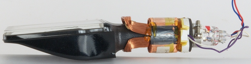 The side of a Sony Watchman monochrome CRT. One of the pairs of deflection coils is easily noticeable.

Radar CRTs
Radar CRTs such as the 7JP4 had a circular screen and scanned the beam from the center outwards. The screen often had two colors, often a bright short persistence color that only appeared as the beam scanned the display and a long persistence phosphor afterglow. When the beam strikes the phosphor, the phosphor brightly illuminates, and when the beam leaves, the dimmer long persistence afterglow would remain lit where the beam struck the phosphor, alongside the radar targets that were "written" by the beam, until the beam re-struck the phosphor.[507][508] The deflection yoke rotated, causing the beam to rotate in a circular fashion.[509]
Oscilloscope CRTs
.jpg)

In oscilloscope CRTs, electrostatic deflection is used, rather than the magnetic deflection commonly used with television and other large CRTs. The beam is deflected horizontally by applying an electric field between a pair of plates to its left and right, and vertically by applying an electric field to plates above and below. Televisions use magnetic rather than electrostatic deflection because the deflection plates obstruct the beam when the deflection angle is as large as is required for tubes that are relatively short for their size. Some Oscilloscope CRTs incorporate post deflection anodes (PDAs) that are spiral-shaped to ensure even anode potential across the CRT and operate at up to 15,000 volts. In PDA CRTs the electron beam is deflected before it is accelerated, improving sensitivity and legibility, specially when analyzing voltage pulses with short duty cycles.[510][197][511]
Microchannel plate
When displaying fast one-shot events, the electron beam must deflect very quickly, with few electrons impinging on the screen, leading to a faint or invisible image on the display. Oscilloscope CRTs designed for very fast signals can give a brighter display by passing the electron beam through a micro-channel plate just before it reaches the screen. Through the phenomenon of secondary emission, this plate multiplies the number of electrons reaching the phosphor screen, giving a significant improvement in writing rate (brightness) and improved sensitivity and spot size as well.[512][513]
Graticules
Most oscilloscopes have a graticule as part of the visual display, to facilitate measurements. The graticule may be permanently marked inside the face of the CRT, or it may be a transparent external plate made of glass or acrylic plastic. An internal graticule eliminates parallax error, but cannot be changed to accommodate different types of measurements.[514] Oscilloscopes commonly provide a means for the graticule to be illuminated from the side, which improves its visibility.[515]
Image storage tubes

These are found in analog phosphor storage oscilloscopes. These are distinct from digital storage oscilloscopes which rely on solid state digital memory to store the image.
Where a single brief event is monitored by an oscilloscope, such an event will be displayed by a conventional tube only while it actually occurs. The use of a long persistence phosphor may allow the image to be observed after the event, but only for a few seconds at best. This limitation can be overcome by the use of a direct view storage cathode-ray tube (storage tube). A storage tube will continue to display the event after it has occurred until such time as it is erased. A storage tube is similar to a conventional tube except that it is equipped with a metal grid coated with a dielectric layer located immediately behind the phosphor screen. An externally applied voltage to the mesh initially ensures that the whole mesh is at a constant potential. This mesh is constantly exposed to a low velocity electron beam from a 'flood gun' which operates independently of the main gun. This flood gun is not deflected like the main gun but constantly 'illuminates' the whole of the storage mesh. The initial charge on the storage mesh is such as to repel the electrons from the flood gun which are prevented from striking the phosphor screen.
When the main electron gun writes an image to the screen, the energy in the main beam is sufficient to create a 'potential relief' on the storage mesh. The areas where this relief is created no longer repel the electrons from the flood gun which now pass through the mesh and illuminate the phosphor screen. Consequently, the image that was briefly traced out by the main gun continues to be displayed after it has occurred. The image can be 'erased' by resupplying the external voltage to the mesh restoring its constant potential. The time for which the image can be displayed was limited because, in practice, the flood gun slowly neutralises the charge on the storage mesh. One way of allowing the image to be retained for longer is temporarily to turn off the flood gun. It is then possible for the image to be retained for several days. The majority of storage tubes allow for a lower voltage to be applied to the storage mesh which slowly restores the initial charge state. By varying this voltage a variable persistence is obtained. Turning off the flood gun and the voltage supply to the storage mesh allows such a tube to operate as a conventional oscilloscope tube.[516]
Vector monitors
Vector monitors were used in early computer aided design systems[517] and are in some late-1970s to mid-1980s arcade games such as Asteroids.[518] They draw graphics point-to-point, rather than scanning a raster. Either monochrome or color CRTs can be used in vector displays, and the essential principles of CRT design and operation are the same for either type of display; the main difference is in the beam deflection patterns and circuits.
Data storage tubes
The Williams tube or Williams-Kilburn tube was a cathode-ray tube used to electronically store binary data. It was used in computers of the 1940s as a random-access digital storage device. In contrast to other CRTs in this article, the Williams tube was not a display device, and in fact could not be viewed since a metal plate covered its screen.
Cat's eye
In some vacuum tube radio sets, a "Magic Eye" or "Tuning Eye" tube was provided to assist in tuning the receiver. Tuning would be adjusted until the width of a radial shadow was minimized. This was used instead of a more expensive electromechanical meter, which later came to be used on higher-end tuners when transistor sets lacked the high voltage required to drive the device.[519] The same type of device was used with tape recorders as a recording level meter, and for various other applications including electrical test equipment.
Charactrons
Some displays for early computers (those that needed to display more text than was practical using vectors, or that required high speed for photographic output) used Charactron CRTs. These incorporate a perforated metal character mask (stencil), which shapes a wide electron beam to form a character on the screen. The system selects a character on the mask using one set of deflection circuits, but that causes the extruded beam to be aimed off-axis, so a second set of deflection plates has to re-aim the beam so it is headed toward the center of the screen. A third set of plates places the character wherever required. The beam is unblanked (turned on) briefly to draw the character at that position. Graphics could be drawn by selecting the position on the mask corresponding to the code for a space (in practice, they were simply not drawn), which had a small round hole in the center; this effectively disabled the character mask, and the system reverted to regular vector behavior. Charactrons had exceptionally long necks, because of the need for three deflection systems.[520][521]
Nimo

Nimo was the trademark of a family of small specialised CRTs manufactured by Industrial Electronics Engineers. These had 10 electron guns which produced electron beams in the form of digits in a manner similar to that of the charactron. The tubes were either simple single-digit displays or more complex 4- or 6- digit displays produced by means of a suitable magnetic deflection system. Having little of the complexities of a standard CRT, the tube required a relatively simple driving circuit, and as the image was projected on the glass face, it provided a much wider viewing angle than competitive types (e.g., nixie tubes).[522] However, their requirement for several voltages and their high voltage made them uncommon.
Flood beam CRT
Flood beam CRTs are small tubes that are arranged as pixels for large video walls like Jumbotrons. The first screen using this technology (called Diamond Vision by Mitsubishi Electric) was introduced by Mitsubishi Electric for the 1980 Major League Baseball All-Star Game. It differs from a normal CRT in that the electron gun within does not produce a focused controllable beam. Instead, electrons are sprayed in a wide cone across the entire front of the phosphor screen, basically making each unit act as a single light bulb.[523] Each one is coated with a red, green or blue phosphor, to make up the color sub-pixels. This technology has largely been replaced with light emitting diode displays. Unfocused and undeflected CRTs were used as grid-controlled stroboscope lamps since 1958.[524]
Print head CRT
CRTs with an unphosphored front glass but with fine wires embedded in it were used as electrostatic print heads in the 1960s. The wires would pass the electron beam current through the glass onto a sheet of paper where the desired content was therefore deposited as an electrical charge pattern. The paper was then passed near a pool of liquid ink with the opposite charge. The charged areas of the paper attract the ink and thus form the image.[525][526]
Zeus thin CRT display
In the late 1990s and early 2000s Philips Research Laboratories experimented with a type of thin CRT known as the Zeus display which contained CRT-like functionality in a flat panel display.[527][528][529][530][531] The devices were demonstrated but never marketed.
Slimmer CRT

Some CRT manufacturers, both LG.Philips Displays (later LP Displays) and Samsung SDI, innovated CRT technology by creating a slimmer tube. Slimmer CRT had the trade names Superslim,[532] Ultraslim,[108] Vixlim (by Samsung)[533] and Cybertube and Cybertube+ (both by LG Philips displays).[534][535] A 21-inch (53 cm) flat CRT has a 447.2-millimetre (17.61 in) depth. The depth of Superslim was 352 millimetres (13.86 in)[536] and Ultraslim was 295.7 millimetres (11.64 in).[537]
Health concerns
Ionizing radiation
CRTs can emit a small amount of X-ray radiation as a result of the electron beam's bombardment of the shadow mask/aperture grille and phosphors. The amount of radiation escaping the front of the monitor is widely considered not to be harmful. The Food and Drug Administration regulations in 21 CFR 1020.10 are used to strictly limit, for instance, television receivers to 0.5 milliroentgens per hour (mR/h) (0.13 µC/(kg·h) or 36 pA/kg) at a distance of 5 cm (2 in) from any external surface; since 2007, most CRTs have emissions that fall well below this limit.[538]
The density of the x-rays that would be generated by a CRT is low because the raster scan of a typical CRT distributes the energy of the electron beam across the entire screen. Voltages above 15,000 volts are enough to generate "soft" x-rays. However, since CRTs may stay on for several hours at a time, the amount of x-rays generated by the CRT may become significant, hence the importance of using materials to shield against x-rays, such as the thick leaded glass and barium-strontium glass used in CRTs.[181]
Concerns about x-rays emitted by CRTs began in 1967 when it was found that TV sets made by General Electric were emitting “X-radiation in excess of desirable levels”. It was later found that TV sets from all manufacturers were also emitting radiation. This caused television industry representatives to be brought before a U.S. congressional committee, which later proposed a federal radiation regulation bill, which became the 1968 Radiation Control for Health and Safety Act. It was recommended to TV set owners to always be at a distance of at least 6 feet from the screen of the TV set, and to avoid "prolonged exposure" at the sides, rear or underneath a TV set. It was discovered that most of the radiation was directed downwards. Owners were also told to not modify their set's internals to avoid exposure to radiation. Headlines about "radioactive" TV sets continued until the end of the 1960s. There once was a proposal by two New York congressmen that would have forced TV set manufacturers to “go into homes to test all of the nation’s 15 million color sets and to install radiation devices in them”. The FDA eventually began regulating radiation emissions from all electronic products.[539]
Toxicity
Older color and monochrome CRTs may have been manufactured with toxic substances, such as cadmium, in the phosphors.[41][540][541][542] The rear glass tube of modern CRTs may be made from leaded glass, which represent an environmental hazard if disposed of improperly.[543] By the time personal computers were produced, glass in the front panel (the viewable portion of the CRT) used barium rather than lead,[citation needed] though the rear of the CRT was still produced from leaded glass. Monochrome CRTs typically do not contain enough leaded glass to fail EPA TCLP tests. While the TCLP process grinds the glass into fine particles in order to expose them to weak acids to test for leachate, intact CRT glass does not leach (The lead is vitrified, contained inside the glass itself, similar to leaded glass crystalware).
Flicker
At low refresh rates (60 Hz and below), the periodic scanning of the display may produce a flicker that some people perceive more easily than others, especially when viewed with peripheral vision. Flicker is commonly associated with CRT as most televisions run at 50 Hz (PAL) or 60 Hz (NTSC), although there are some 100 Hz PAL televisions that are flicker-free. Typically only low-end monitors run at such low frequencies, with most computer monitors supporting at least 75 Hz and high-end monitors capable of 100 Hz or more to eliminate any perception of flicker.[544] Though the 100 Hz PAL was often achieved using interleaved scanning, dividing the circuit and scan into two beams of 50 Hz. Non-computer CRTs or CRT for sonar or radar may have long persistence phosphor and are thus flicker free. If the persistence is too long on a video display, moving images will be blurred.
High-frequency audible noise
50 Hz/60 Hz CRTs used for television operate with horizontal scanning frequencies of 15,734 Hz (for NTSC systems) or 15,625 Hz (for PAL systems).[545] These frequencies are at the upper range of human hearing and are inaudible to many people; however, some people (especially children) will perceive a high-pitched tone near an operating television CRT.[546] The sound is due to magnetostriction in the magnetic core and periodic movement of windings of the flyback transformer[547] but the sound can also be created by movement of the deflection coils, yoke or ferrite beads.[548]
This problem does not occur on 100/120 Hz TVs and on non-CGA (Color Graphics Adapter) computer displays, because they use much higher horizontal scanning frequencies that produce sound which is inaudible to humans (22 kHz to over 100 kHz).
Implosion

High vacuum inside glass-walled cathode-ray tubes permits electron beams to fly freely—without colliding into molecules of air or other gas. If the glass is damaged, atmospheric pressure can collapse the vacuum tube into dangerous fragments which accelerate inward and then spray at high speed in all directions. Although modern cathode-ray tubes used in televisions and computer displays have epoxy-bonded face-plates or other measures to prevent shattering of the envelope, CRTs must be handled carefully to avoid personal injury.[549]
Implosion protection
Early CRTs had a glass plate over the screen that was bonded to it using glue,[185] creating a laminated glass screen: initially the glue was PVA glue[550] while later versions such as the LG Flatron used a resin, perhaps a UV-curable resin.[551][386] Later CRTs instead use a tensioned metal rim band mounted around the perimeter that also provides mounting points for the CRT to be mounted to a housing. In a 19-inch CRT, the tensile stress in the rim band is 70kg/cm2.[552] Older CRTs were mounted to the TV set using a frame. The band is tensioned by heating it before mounting it on the CRT, the band then cools, shrinking in size which puts the glass under compression,[553][185] strengthening the glass reducing the necessary thickness (and hence weight) of the glass. This makes the band an integral component that should never be removed; attempting to remove it may cause the CRT to implode.[358] The rim band prevents the CRT from imploding should the screen be broken. The rim band is glued to the perimeter of the CRT using epoxy, preventing cracks from spreading beyond the screen and into the funnel.[554] The PVA glue degrades over time creating a "cataract", a ring of degraded glue around the edges of the CRT that does not allow light from the screen to pass through.[550]
Electric shock
To accelerate the electrons from the cathode to the screen with sufficient velocity to achieve sufficient image brightness, a very high voltage (EHT or extra-high tension) is required,[555] from a few thousand volts for a small oscilloscope CRT to tens of kV for a larger screen color TV. This is many times greater than household power supply voltage. Even after the power supply is turned off, some associated capacitors and the CRT itself may retain a charge for some time and therefore dissipate that charge suddenly through a ground such as an inattentive human grounding a capacitor discharge lead. An average monochrome CRT may use 1 to 1.5 kV of anode voltage per inch.[556][310]
Security concerns
Under some circumstances, the signal radiated from the electron guns, scanning circuitry, and associated wiring of a CRT can be captured remotely and used to reconstruct what is shown on the CRT using a process called Van Eck phreaking.[557] Special TEMPEST shielding can mitigate this effect. Such radiation of a potentially exploitable signal, however, occurs also with other display technologies[558] and with electronics in general.[citation needed]
Recycling
Due to the toxins contained in CRT monitors the United States Environmental Protection Agency created rules (in October 2001) stating that CRTs must be brought to special e-waste recycling facilities. In November 2002, the EPA began fining companies that disposed of CRTs through landfills or incineration. Regulatory agencies, local and statewide, monitor the disposal of CRTs and other computer equipment.[559]
As electronic waste, CRTs are considered one of the hardest types to recycle.[560] CRTs have relatively high concentration of lead and phosphors (not phosphorus), both of which are necessary for the display. There are several companies in the United States that charge a small fee to collect CRTs, then subsidize their labor by selling the harvested copper, wire, and printed circuit boards. The United States Environmental Protection Agency (EPA) includes discarded CRT monitors in its category of "hazardous household waste"[561] but considers CRTs that have been set aside for testing to be commodities if they are not discarded, speculatively accumulated, or left unprotected from weather and other damage.[562]
Various states participate in the recycling of CRTs, each with their reporting requirements for collectors and recycling facilities. For example, in California the recycling of CRTs is governed by CALRecycle, the California Department of Resources Recycling and Recovery through their Payment System..[563] Recycling facilities that accept CRT devices from business and residential sector must obtain contact information such as address and phone number to ensure the CRTs come from a California source in order to participate in the CRT Recycling Payment System.
In Europe, disposal of CRT televisions and monitors is covered by the WEEE Directive.[564]
Multiple methods have been proposed for the recycling of CRT glass. The methods involve thermal, mechanical and chemical processes.[565][566][567][568] All proposed methods remove the lead oxide content from the glass. Some companies operated furnaces to separate the lead from the glass.[569] A coalition called the Recytube project was once formed by several European companies to devise a method to recycle CRTs.[6] The phosphors used in CRTs often contain rare earth metals.[570][571][572][348] A CRT contains about 7g of phosphor.[573]
The funnel can be separated from the screen of the CRT using laser cutting, diamond saws or wires or using an electrically heated nichrome wire.[574][575][576][577][578][579]
Leaded CRT glass was sold to be remelted into other CRTs,[80] or even broken down and used in road construction or used in tiles,[101][580] concrete, concrete and cement bricks,[581] fiberglass insulation or used as flux in metals smelting.[582][583]
A considerable portion of CRT glass is landfilled, where it can pollute the surrounding environment.[6] It is more common for CRT glass to be disposed of than to be recycled.[584]
See also
Basics of cathode rays and discharge in low-pressure gas:
Light production by cathode rays:
Manipulating the electron beam:
- Blanking (video)
- Deflection yoke
- Electron beam processing
- Electrostatic deflection
- Electrostatic lens
- Magnetic deflection
- Magnetic lens
Applying CRT in different display-purpose:
- Analog television
- Image displaying
- Comparison of CRT, LCD, plasma, and OLED
- Comparison of display technology
- Computer monitor
- CRT projector
- Image dissector
- Monochrome monitor
- Monoscope
- Oscilloscope
- Cathode-ray oscilloscope
- Overscan
- Raster scan
- Scan line
Miscellaneous phenomena:
Historical aspects:
- Direct-view bistable storage tube
- Flat panel display
- Geer tube
- History of display technology
- Image dissector
- LCD television, LED-backlit LCD, LED display
- Penetron
- Surface-conduction electron-emitter display
- Trinitron
Safety and precautions:
References
- ^ "Power supply stabilization circuit with separate AC/DC negative feedback paths".
- ^ "History of the Cathode Ray Tube". About.com. Retrieved 4 October 2009.
- ^ a b "How Computer Monitors Work". Retrieved 4 October 2009.
- ^ Topic 7 |The Cathode-Ray Tube Archived 15 December 2017 at the Wayback Machine. aw.com. 2003-08-01
- ^ repairfaq.org – Sam's Laser FAQ – Vacuum Technology for Home-Built Gas Lasers Archived 9 October 2012 at the Wayback Machine. repairfaq.org. 2012-08-02
- ^ a b c d Dhir, Ravindra K.; Limbachiya, Mukesh C.; Dyer, Thomas D. (2001). Recycling and Reuse of Glass Cullet: Proceedings of the International Symposium Organised by the Concrete Technology Unit and Held at the University of Dundee, Scotland, UK on 19-20 March 2001. Thomas Telford. ISBN 978-0-7277-2994-1.[page needed]
- ^ a b c d e f g h Musgraves, J. David; Hu, Juejun; Calvez, Laurent (8 November 2019). "Cathod Ray-Tube Design". Springer Handbook of Glass. Springer Nature. p. 1367. ISBN 978-3-319-93728-1.
{{cite book}}: External link in|chapterurl=|chapterurl=ignored (|chapter-url=suggested) (help) - ^ Katzmaier, David. "Remember when TVs weighed 200 pounds? A look back at TV trends over the years". CNET.
- ^ https://docs.sony.com/release/PVM4300.pdf
- ^ "Cathode-ray tube and its manufacturing method, and electron gun".
- ^ a b c "How Computer Monitors Work". HowStuffWorks. 16 June 2000.
- ^ "Cathode Ray Tube (CRT)". Circuit Globe. 6 June 2017.
- ^ "Home Page for ECE 3065 -- Electromagnetic Applications". propagation.ece.gatech.edu.
- ^ Rosch, Winn L. (12 December 1989). "Lab Notes". PC Mag. pp. 275–297.
- ^ Martin, Andre (1986), "Cathode Ray Tubes for Industrial and Military Applications", in Hawkes, Peter (ed.), Advances in Electronics and Electron Physics, Volume 67, Academic Press, p. 183, ISBN 9780080577333,
Evidence for the existence of "cathode-rays" was first found by Plücker and Hittorf ...
- ^ Ferdinand Braun (1897) "Ueber ein Verfahren zur Demonstration und zum Studium des zeitlichen Verlaufs variabler Ströme" (On a process for the display and study of the course in time of variable currents), Annalen der Physik und Chemie, 3rd series, 60: 552–559.
- ^ a b c d e f g h i j k l m n o p Thorn-AEI Radio Valves and Tubes Limited (1964). Electrons in Picture Tubes. United Kingdom.
{{cite book}}: CS1 maint: location missing publisher (link) - ^ Kenjiro Takayanagi: The Father of Japanese Television, NHK (Japan Broadcasting Corporation), 2002, retrieved 23 May 2009.
- ^ Forrester, Chris (2011). High Above: The untold story of Astra, Europe's leading satellite company. Springer Science & Business Media. p. 220. ISBN 978-3-642-12009-1.
- ^ a b Albert Abramson, Zworykin, Pioneer of Television, University of Illinois Press, 1995, p. 231. ISBN 0-252-02104-5.
- ^ Popular Photography, November 1990, page 5
- ^ Albert Abramson, Zworykin, Pioneer of Television, University of Illinois Press, 1995, p. 84. ISBN 0-252-02104-5.
- ^ "RCA Surrenders Rights to Four Trade-Marks," Radio Age, October 1950, p. 21.
- ^ Hart, Hugh (28 January 2010). "Jan. 29, 1901: DuMont Will Make TV Work". Wired.
- ^ Telefunken, Early Electronic TV Gallery, Early Television Foundation.
- ^ 1934–35 Telefunken, Television History: The First 75 Years.
- ^ "Telefunken RFB/T2". www.earlytelevision.org.
- ^ Television Digest, 1949 issue
- ^ a b c https://worldradiohistory.com/Archive-Radio-Age/ElectronicAge-1964-Autumn.pdf
- ^ a b https://www.earlytelevision.org/motorola_prototype_crt.html#:~:text=The%2023EGP22%20was%20the%20first,dated%20December%2C%201960%20thru%201962.
- ^ a b https://vintagetek.org/wp-content/uploads/2017/07/Tek-CRT-History-Keller-Oct-2007-Pt5.pdf
- ^ "Raytheon Model M-1601 console television receiver | Science Museum Group Collection". collection.sciencemuseumgroup.org.uk.
- ^ "Westinghouse 19 Inch Color TV Ad". www.earlytelevision.org.
- ^ a b "15GP22 Color CRT". www.earlytelevision.org.
- ^ Knowles, Tim Mekeel And Laura. "RCA pioneers remember making the first color TV tube". LancasterOnline.
- ^ Early Television Museum. "DuMont Experimental Color".
- ^ https://www.earlytelevision.org/pdf/zenith_rectangular_crt.pdf
- ^ "US Patent for Color picture tube Patent (Patent # 3,989,977 issued November 2, 1976) - Justia Patents Search". patents.justia.com.
- ^ "Rare earth activated indium borate cathodoluminescent phosphors".
- ^ "Rare earth activated yttrium and gadolinium oxy-chalcogenide phosphors".
- ^ a b c http://bitsavers.trailing-edge.com/components/rca/crt/TPM-1508A_RCA_Phosphors_Oct61.pdf
- ^ a b c Toshiba Corporation. "東芝未来科学館:世界初のブラック・ストライプ方式ブラウン管" (in Japanese).
- ^ "Cathode ray tube color screen and method of producing same".
- ^ "The Cathode Ray Tube site, Cathode Ray Tubes". www.crtsite.com.
- ^ a b "21AXP22". www.earlytelevision.org.
- ^ "CBS and Westinghouse 22 Inch Rectangular Color Tubes". www.earlytelevision.org.
- ^ "1988 vs. 2008: A Tech Retrospective". PCWorld. 22 February 2008.
- ^ https://docs.sony.com/release/PVM4300.pdf The KX-45ED1 by sony was even larger, at 45 visible inches, and it was released in 1988 in Japan, but i couldn't find any reliable sources about it
- ^ "RCA 31 Inch CRT". www.earlytelevision.org.
- ^ "Geer Experimental Color CRT". www.earlytelevision.org.
- ^ Taylor, Alan. "50 Years Ago: The World in 1961 - The Atlantic". www.theatlantic.com.
- ^ "Fairchild Flat Screen CRT". www.earlytelevision.org.
- ^ "Flat Screen TV in 1958 - Popular Mechanics (Jan, 1958)".
- ^ a b Corporation, Bonnier (5 August 1986). "Popular Science". Bonnier Corporation – via Google Books.
- ^ a b Corporation, Bonnier (5 April 1992). "Popular Science". Bonnier Corporation – via Google Books.
- ^ a b c d e f Warren, Rich. "TV MAKERS TUNING IN TO FLAT SCREENS TO HELP ROUND OUT SALES". chicagotribune.com.
- ^ a b c "Prototype CRT's". www.crtsite.com.
- ^ "History of the CRT TV". BT.com.
- ^ a b "Toshiba : Press Releases 21 December, 1995".
- ^ "LCDs to outsell CRT monitors soon: IDC". amp.smh.com.au.
- ^ "IDC: LCDs to outsell CRT monitors in 2003 | Computerworld". www.computerworld.com.
- ^ Maslog-Levis, Kristyn. "LCDs outsell CRTs in Q4 2003". ZDNet.
- ^ "LCDs Overtake and Outsell CRTs in Q3 2004!". Audioholics Home Theater, HDTV, Receivers, Speakers, Blu-ray Reviews and News.
- ^ "LCD monitors outsold CRTs in Q3, says DisplaySearch | EE Times".
- ^ September 2005, TVTechnology 28. "Canada: Daytek Adds 40-Inch LCD HD". TVTechnology.
{{cite web}}: CS1 maint: numeric names: authors list (link) - ^ "LCD TV shipments beat CRT in Japan in 2005". ARN.
- ^ "Big-screen CRT TV business in Japan all but over". Macworld. 24 July 2006.
- ^ Staff, C. I. O. (24 July 2006). "Big-Screen CRT TV Biz in Japan All But Finished". CIO.
- ^ "LCDs outsell CRTs in Europe | Macworld". www.macworld.com.
- ^ Sherwood, James. "Global LCD TV sales overtake CRT". www.theregister.com.
- ^ "Archived copy". Archived from the original on 11 October 2013. Retrieved 3 April 2018.
{{cite web}}: CS1 maint: archived copy as title (link) - ^ Mitra, Amit. "Indians switch off cathode ray TVs". @businessline.
- ^ "Canon signals end of the road for SED TV dreams". Good Gear Guide.
- ^ "Three more years of Videocon CRT demand?". 9 January 2015.
- ^ a b "A look at where California's CRT glass is going". 12 March 2020.
- ^ "Saying Goodbye To Old Technology — And A Legendary NYC Repair Shop". NPR.org.
- ^ "Onida exits DVD business, aims to phase out CRT TV manufacturing by 2015". Business Standard.
- ^ "Price fixing settlement: If you owned a TV in 1995 you could get money back". Global News.
- ^ Levine, Dan (1 June 2015). "Companies in cathode ray tube price fixing lawsuit reach $528 million deal". Reuters.
- ^ a b c "CRTs going down the tubes? Hardly". MIT News | Massachusetts Institute of Technology.
- ^ "CNN.com - Are you looking at your last CRT? - February 15, 2002". edition.cnn.com.
- ^ McClung, By Pat; Jul 25, 1999. "FlexScan L66: A sound choice in flat-panel displays -". FCW.
{{cite web}}:|first2=has numeric name (help)CS1 maint: numeric names: authors list (link) - ^ "GE Announces Tube Plant Closing; 790 Jobs Cut". AP NEWS.
- ^ "Hitachi Will Still Manufacture CRT Monitors - ExtremeTech". www.extremetech.com.
- ^ Blincoe, Robert. "Hitachi to ditch CRT monitors". www.theregister.com.
- ^ a b "Sony to stop making old-style cathode ray tube TVs". MarketWatch.
- ^ "Thomson shuts down American picture tube production | TV Technology". www.tvtechnology.com.
- ^ Certain Color Television Receivers from China, Invs. 731-TA-1034 (Final). DIANE Publishing. ISBN 9781457820526 – via Google Books.
- ^ "Hitachi, Matsushita, Toshiba cement LCD venture plan | Computerworld". www.computerworld.com.
- ^ a b Williams, Martyn (27 July 2006). "Panasonic-Toshiba venture to shut Malaysia CRT plant". Network World.
- ^ "Panasonic China stops CRT TV production at Shandong plant". DIGITIMES.
- ^ "Retrotechtacular: Some Of The Last CRTs From The Factory Floor". 30 November 2018.
- ^ "Full Page Reload". IEEE Spectrum: Technology, Engineering, and Science News.
- ^ "Samsung SDI Struggles to Close CRT Lines". m.koreatimes.co.kr. 10 December 2007.
- ^ "Samsung Hungary to Halt CRT Production". world.kbs.co.kr.
- ^ "Samsung SDI halts CRT production in Malaysia plant - Pulse by Maeil Business News Korea". m.pulsenews.co.kr.
- ^ "Samsung SDI halts CRT production in Malaysia plant". www.mk.co.kr. 3 April 2012.
- ^ "Cathode Ray Technology". www.crtsite.com.
- ^ "Cathode Ray Technology B.V. Engineering Model Type D10-XXX". lampes-et-tubes.info.
- ^ "Videocon shuts down furnaces - and stokes concerns". 22 October 2015.
- ^ a b "With demand dwindling, questions swirl around Videocon". 1 February 2018.
- ^ a b Elliott, Bobby (3 March 2016). "Videocon begins accepting CRT glass again".
- ^ "Ekranas files for bankruptcy, Vilniaus Vingis braces for worst". www.baltictimes.com.
- ^ Bush, Steve (27 January 2006). "LG.Philips seeks bankruptcy protection in Europe".
- ^ "LCD plant coming soon after CRT close-down". ComputerWeekly.com.
- ^ a b "Samsung introduces 2007 LCD, plasma, DLP and CRT lineup". Engadget.
- ^ https://www.techradar.com/news/television/tv/world-s-thinnest-crt-tv-bucks-all-trends-167665#:~:text=Specifically%2C%20Korean%20firm%20LG%20has,select%20markets%20later%20this%20year.
- ^ a b Solca, Bogdan. "LG Presents the Slimmest CRT TV Display". softpedia.
- ^ "LG's Classic TV gives old CRT new legs". Engadget.
- ^ "LG Goes Retro, Introduces New CRT TV | TechHive". www.techhive.com.
- ^ "LG, Samsung try to save the CRT". amp.smh.com.au.
- ^ February 2009, Dean Evans 06. "What's happening to all the CRT TVs?". TechRadar.
{{cite web}}: CS1 maint: numeric names: authors list (link) - ^ Ravikumar, R. "Rise of flat-screen televisions lowers the curtain on the bulky box". @businessline.
- ^ Wong, May (22 October 2006). "Flat Panels Drive Old TVs From Market". AP via USA Today. Retrieved 8 October 2006.
- ^ Shim, Richard. "LG.Philips Displays ups production of slim CRTs". CNET.
- ^ "LG, Samsung try to save the CRT". The Sydney Morning Herald. 19 August 2005.
- ^ "Samsung unveils HDTV-compatible CRT - Audio Visual - News - HEXUS.net". m.hexus.net.
- ^ a b https://www.scmp.com/article/404922/philips-division-launches-slim-crts
- ^ "World's slimmest CRT digital TV built". amp.smh.com.au.
- ^ "The Standard TV" (PDF). Veritas et Visus. Retrieved 12 June 2008.
- ^ "End of an era". The San Diego Union-Tribune. 20 January 2006. Archived from the original on 15 June 2008. Retrieved 12 June 2008.
- ^ "Matsushita says good-bye to CRTs". engadgetHD. 1 December 2005. Archived from the original on 14 January 2009. Retrieved 12 June 2008.
- ^ "SlimFit HDTV". Samsung. Archived from the original on 10 January 2008. Retrieved 12 June 2008.
- ^ "The future is flat as Dixons withdraws sale of 'big box' televisions". London Evening Standard. 26 November 2006. Archived from the original on 5 May 2013. Retrieved 3 December 2006.
- ^ a b "Donkey Kong's failing liver: What the death of the CRT display technology means for classic arcade machines". 3 March 2017.
- ^ "Nintendo Entertainment System Specs". CNET. Retrieved 8 September 2020.
- ^ Pal, Soumyadeep. "The Iconic Boeing 747 Heads Into The Sunset. An Enduring Legacy". QNewsHub. Retrieved 8 September 2020.
- ^ "The Boeing 747-400 Is Still Updated With Floppy Disks - Here's Why". Simple Flying. 11 August 2020. Retrieved 8 September 2020.
- ^ "Asus ROG Swift 360Hz PG259QN Review". PCMAG.
- ^ a b c "We played modern games on a CRT monitor - and the results are phenomenal | Eurogamer". www.eurogamer.net.
- ^ Morrison, Geoffrey. "Which TV is best for PS5 and Xbox Series X?". CNET.
- ^ "LG C9 OLED Review (OLED55C9PUA, OLED65C9PUA, OLED77C9PUA)". RTINGS.com.
- ^ https://www.gizchina.com/2020/11/07/lg-admits-that-oled-tvs-will-have-problems-with-variable-refresh-rate-vrr-below-120-hz/
- ^ "OLED Monitors In 2020 : Current Market Status". DisplayNinja. 23 November 2020.
- ^ Morrison, Geoffrey. "Motion blur on 4K TVs: What it is and how to fight it". CNET.
- ^ "Samsung SyncMaster 997MB - CRT monitor - 19" Series Specs". CNET.
- ^ "Samsung C32HG70 Review 2020: What You Need To Know". DisplayNinja. 29 October 2020.
- ^ https://www.cnet.com/news/samsung-qled-vs-lg-oled-how-the-two-best-tv-technologies-compare-in-2020/#:~:text=OLED%20stands%20for%20%22organic%20light%20emitting%20diode.%22&text=QLED%20is%20a%20variation%20of,relies%20on%20an%20LED%20backlight.
- ^ Kim, Chul (3 October 2002). "Production of shadow-mask-improved technology". Journal of Materials Processing Technology. 127 (3): 409–418. doi:10.1016/s0924-0136(02)00435-1.
- ^ "MultiSync 25th Anniversary - The Evolution of the MultiSync | NEC Display Solutions". www.nec-display.com.
- ^ Bagher, Askari Mohammad; Vahid, Mirzaei Mahmoud Abadi; Mohsen, Mirhabibi (19 May 2017). "A Review of Challenges in Display Technology". International Journal of Electrical Components and Energy Conversion. 3 (2): 26. doi:10.11648/j.ijecec.20170302.12.
{{cite journal}}: CS1 maint: unflagged free DOI (link) - ^ https://www.digitaltrends.com/computing/crt-monitor-modern-gaming
- ^ "Large metal cone cathode ray tubes, and envelopes therefor". calls it faceplate "CRT having a contrast enhancing exterior coating and method of manufacturing the same". also calls it faceplate "Funnel for use in a cathode ray tube". calls it a panel https://www.calrecycle.ca.gov/docs/cr/electronics/resources/publications/glassmff.pdf also calls it a panel
- ^ https://www.illinoisrecycles.org/wp-content/uploads/2014/10/150618_T_3.1_ChrisCahnovsky.pdf
- ^ a b c Ha, Kuedong; Shin, Soon-Cheol; Kim, Do-Nyun; Lee, Kue-Hong; Kim, Jeong-Hoon (2006). "Development of a 32-in. slim CRT with 125° deflection". Journal of the Society for Information Display. 14 (1): 65. doi:10.1889/1.2166838.
- ^ a b c d e https://dnr.mo.gov/env/hwp/escrap/docs/crttcp99.pdf
- ^ a b "America's Television Graveyards". www.vice.com.
- ^ "Processing technique for straight tube necking glass cone for CRT".
- ^ "Method of reforming glass face plates on a shaping mold".
- ^ "CRT funnel with positioning reference portions".
- ^ "Glass panel and a cathode ray tube including the same".
- ^ "Method for forming rectangular face plate".
- ^ "Funnel for cathode ray tube".
- ^ "6. CRT Glass". ric.
- ^ US EPA, OLEM (22 February 2016). "Frequent Questions About the Regulation of Used Cathode Ray Tubes (CRTs) and CRT Glass". US EPA.
- ^ Main, Jeremy (11 May 2010). Quality Wars: The Triumphs and Defeats of American Business. Simon and Schuster. ISBN 9781439138458 – via Google Books.
- ^ a b c d e f g h i j k l m n http://gradllc.com/images/Def.pdf
- ^ a b c "FLATRON". yumpu.com.
- ^ "Flat CRT with improved coating".
- ^ a b https://www.glass-ts.com/userfiles/files/2003-08%20New%20Approach%20to%20Cathode%20Ray%20Tube%20(CRT)%20Recycling.pdf
- ^ a b c d e f g h i https://spie.org/samples/TT54.pdf
- ^ a b c d "SER FAQ: TVFAQ: Color CRTs - shadow masks and aperture grills". www.repairfaq.org.
- ^ a b c d "SER FAQ: TVFAQ: CRT convergence adjustment". www.repairfaq.org.
- ^ "Convergence Test Patterns". www.mediacollege.com.
- ^ "Corning Asahi Video to sell plant assets to Chinese supplier | EE Times".
- ^ "CPT expects limited impact from Asahi Glass CRT plant closure in Taiwan". DIGITIMES.
- ^ "Asahi Techno Vision to close Singapore plant". 12 June 2007.
- ^ "Asahi Glass restructures CRT funnel manufacturing". 13 January 2005.
- ^ "History". Nippon Electric Glass Co., Ltd.
- ^ "4 CRT glass makers fined for price fixing". koreatimes. 11 December 2011.
- ^ "Corning to Close Plant and Cut 1000 Jobs". www.photonics.com.
- ^ Shim, Richard. "Corning to close TV glass plant". ZDNet.
- ^ "日本電気硝子、CRT用ガラスの国内生産を9月末で停止、国内需要の消滅に対応". BCN+R.
- ^ Industry and Trade Summary: Television Picture Tubes and other Cathode-Ray Tubes. DIANE Publishing. ISBN 9781457825903 – via Google Books.
- ^ "American Video Glass Company: TV glass plant officially dedicated". archive.glassonline.com.
- ^ https://www.bizjournals.com/pittsburgh/stories/2006/12/04/daily32.html
- ^ a b c d "テレビ今昔物語". www.gic.jp.
- ^ a b "Cathode ray tube | University of Oxford Department of Physics". www2.physics.ox.ac.uk.
- ^ "SER FAQ: TVFAQ: Should I be worried about X-ray exposure while servicing a TV or monitor?". repairfaq.cis.upenn.edu.
- ^ "SER FAQ: TVFAQ: X-ray and other EM emission from my TV or monitor?". repairfaq.cis.upenn.edu.
- ^ a b "X-Rays from TV Sets - Are They Harmful?". Radio News. November 1958.
- ^ a b Lee, Ching-Hwa; Hsi, Chi-Shiung (1 January 2002). "Recycling of Scrap Cathode Ray Tubes". Environmental Science & Technology. 36 (1): 69–75. Bibcode:2002EnST...36...69L. doi:10.1021/es010517q. PMID 11811492.
- ^ Ganesan, Sanka; Pecht, Michael G. (31 March 2006). Lead-free Electronics. John Wiley & Sons. ISBN 9780470007792 – via Google Books.
- ^ Compton, Kenneth (5 December 2003). Image Performance in CRT Displays. SPIE Press. ISBN 9780819441447 – via Google Books.
- ^ a b c d e f g h i j Compton, Kenneth (5 December 2003). Image Performance in CRT Displays. SPIE Press. ISBN 9780819441447 – via Google Books.
- ^ a b c d [patents.google.com/patent/US5096445A/en "Anode connector assembly for a cathode ray tube"].
{{cite web}}: Check|url=value (help) - ^ "Antiglare/antistatic coating for CRT".
- ^ March 2002, Philippe Ramelet 19. "Comparison: Twelve 19" CRT Monitors". Tom's Hardware.
{{cite web}}: CS1 maint: numeric names: authors list (link) - ^ "Inner surface specular reflection suppression in flat CRT faceplate".
- ^ "Electrical grounding of CRT antistatic/antireflective coating".
- ^ a b "Color cathode ray tube and water resistant glass frit".
- ^ https://ipen.org/sites/default/files/documents/Looking-through-glass-CRT-recycling-in-India.pdf
- ^ Xu, Qingbo; Li, Guangming; He, Wenzhi; Huang, Juwen; Shi, Xiang (August 2012). "Cathode ray tube (CRT) recycling: Current capabilities in China and research progress". Waste Management. 32 (8): 1566–1574. doi:10.1016/j.wasman.2012.03.009. PMID 22542858.
- ^ "RACS - Pyrex CRT Rebuilding". www.earlytelevision.org.
- ^ http://www.nostalgiatech.co.uk/GB470885A.pdf
- ^ https://vintagetek.org/ceramic-strips/
- ^ a b "The Cathode Ray Tube site. oscilloscope crt's". www.crtsite.com.
- ^ a b c d e f "The Monochrome Tube". www.oldtellys.co.uk.
- ^ a b "SER FAQ: TVFAQ: Additional information on discharging CRTs". repairfaq.cis.upenn.edu.
- ^ a b https://wiki.arcadeotaku.com/images/c/c6/Toei_TC-L292K_Manual.pdf
- ^ "TV and Monitor CRT (Picture Tube) Information". www.repairfaq.org. "Cathode-ray tube magnetic shield". "Method of fabricating a cathode ray tube having a conductive metallic coating therein".
- ^ a b "40CB4 @ The Valve Museum". www.r-type.org.
- ^ a b "CRT funnel coating apparatus and method".
- ^ a b http://www.crtsolutions.com/CRTSafety.pdf
- ^ a b c https://eti.pg.edu.pl/documents/176568/264302/module%202%20cathode%20ray%20tube.doc
- ^ Practical Television, November 2001 issue 120° deflection "High deflection angle CRT display". "TV and Monitor CRT (Picture Tube) Information". repairfaq.cis.upenn.edu. 90 degrees in monitors, 110 in TVs
- ^ a b "M14-170W @ The Valve Museum". www.r-type.org.
- ^ "Color Picture Tubes". www.earlytelevision.org.
- ^ Fink, Wesley. "Buyer's Guide: High End System - July 2004". www.anandtech.com.
- ^ https://wiki.arcadeotaku.com/images/c/c6/Crt.jpg
- ^ https://web.archive.org/web/20071013164327/http://www.lgphilips-displays.com/english/download/LGPD%20BROCH%20APR07_3.pdf . 17 March 2003 https://web.archive.org/web/20030317014636/http://www.lgphilips-displays.com/download/ezFlat_HB.pdf. Archived from the original (PDF) on 17 March 2003.
{{cite web}}: Missing or empty|title=(help) https://hardforum.b-cdn.net/data/attachment-files/2020/08/368434_LRG_DSC04662.jpg - ^ http://www.earlytelevision.org/pdf/rca_lancaster_color_tv_conversion_power_tubes.pdf https://frank.pocnet.net/sheets/202/2/23EGP22.pdf https://frank.pocnet.net/sheets/127/suppinfo/index3.pdf
- ^ a b c d http://www.one-electron.com/Archives/GE/GE_Cathode%20Ray%20Tube%20Dept%201958%20Syracuse%20Factory%20Brochure.pdf
- ^ "Matsushita 40CB4 1.5" Viewfinder CRT". lampes-et-tubes.info.
- ^ "The Cathode ray Tube site. Television CRT's". www.crtsite.com.
- ^ "World's Smallest Trinitron". www.earlytelevision.org.
- ^ "Indextron". Visions4 Magazine. 29 December 2016.
- ^ Sugawara, Tsunehiko; Kuroki, Yuichi; Yano, Tetsuji; Shibata, Shuichi (2006). "Recent Advances in Strengthening Glass Material for CRT". Information and Media Technologies. 1 (1): 1–6. doi:10.11185/imt.1.1.
- ^ Sugawara, Tsunehiko; Shimizu, Naoya; Murakami, Toshide (2002). "Recent Developments in Reducing Bulkiness of CRT Glass Bulbs". 한국정보디스플레이학회:학술대회논문집: 359–363.
- ^ http://var.glassonline.com/uploads/publications/section_articles/articlePDF/asahiglassgti1-99.pdf
- ^ a b c https://worldradiohistory.com/hd2/IDX-Business/Books/Regulation/IDX/Radio-Operating-Questions-&-Answers-12th-OCR-Page-0494.pdf
- ^ "Cathode structure for color cathode ray tube".
- ^ a b c d e f g h i j k l m n Thorn-AEI Radio Valves and Tubes Limited (1968). Electrons in Shadow-mask Colour Tubes. United Kingdom.
{{cite book}}: CS1 maint: location missing publisher (link) - ^ a b "Cathode ray tube having symmetrical anode potential".
- ^ Ibrahim, K. F. (14 September 2007). Newnes Guide to Television and Video Technology: The Guide for the Digital Age - from HDTV, DVD and flat-screen technologies to Multimedia Broadcasting, Mobile TV and Blu Ray. Elsevier. ISBN 9780080550664 – via Google Books.
- ^ "Method for applying an internal coating to a cathode ray tube".
- ^ https://www.rfcafe.com/references/electrical/NEETS-Modules/NEETS-Module-06-2-21-2-30.htm
- ^ a b "Cathode-ray tube with aluminized screen".
- ^ "What is CRT (Cathode Ray Tube)? definition, block diagram and working of CRT". 19 May 2018.
- ^ a b Ozawa, Lyuji (15 January 2002). "Electron flow route at phosphor screens in CRTs". Materials Chemistry and Physics. 73 (2): 144–150. doi:10.1016/s0254-0584(01)00360-1.
- ^ a b Solomos, E. (20 December 1979). "A projection graphic display for the computer aided analysis of bubble chamber images". Nuclear Instruments and Methods. 167 (2): 305–311. Bibcode:1979NucIM.167..305S. doi:10.1016/0029-554X(79)90019-3.
- ^ "CRT anode cap".
- ^ "Final Anode".
- ^ "SER FAQ: TVFAQ: Arcing, sparking, or corona from CRT HV anode (red wire/suction cup)". repairfaq.cis.upenn.edu.
- ^ "SER FAQ: TVFAQ: Removing the CRT HV connector". www.repairfaq.org.
- ^ "Apparatus for fusion-welding anode button to crt funnel". Office, United States Patent (5 December 1969). "Official Gazette of the United States Patent Office". The Office – via Google Books. press "Anode button for a cathode ray tube". nested design "Connector assembly for anode button of a cathode ray tube". clip and cap design, x-rays
- ^ "CRT Anode cap".
- ^ "Connector assembly for anode ring of cathode ray tube".
- ^ a b c http://www.repairfaq.org/sam/reppic/horiz-tv.pdf
- ^ https://patents.google.com/patent/US4825129
- ^ a b c "TV X-Rays". Radio Electronics. April 1970.
- ^ "Glass support rod for use in electron-gun mount assemblies".
- ^ https://vintagetek.org/crt-manufacturing/
- ^ a b "Method for heat sealing a gun mount in a CRT neck".
- ^ a b . 2 May 2006 https://web.archive.org/web/20060502053742/http://www.lgphilips-displays.com/english/download/CPT_Manu_Process.pdf. Archived from the original (PDF) on 2 May 2006.
{{cite web}}: Missing or empty|title=(help) - ^ "DuMont 14AP4". www.earlytelevision.org.
- ^ "Narrow-neck CRT having a large stem pin circle".
- ^ "Method for spot-knocking an electron gun assembly of a cathode ray tube".
- ^ "Method for spot-knocking an electron gun mount assembly of a CRT".
- ^ "Cathode ray tube processing".
- ^ Practical Television, June 2001 issue
- ^ https://elektrotanya.com/files/forum/2014/03/kepcsofutes-mero_[ET].pdf
- ^ a b "Indirectly heated cathode body structure for cathode-ray tube".
- ^ a b "Function of Electron Gun Assembly in CRT (Cathode Ray Tube)". 16 November 2015.
- ^ "Method of manufacturing cathode assembly".
- ^ "CRT-Cathode Ray Tube". 25 September 2009.
- ^ Blackburn (August 1955). "The Cathode-Ray Tube". The Radio Constructor. United Kingdom.
{{cite magazine}}: Unknown parameter|First=ignored (|first=suggested) (help) - ^ http://lateblt.tripod.com/bit71.txt
- ^ "Cathode assembly for CRT electron gun - has protective screen around cathode emitter between emitter and hole in insulator support of cylindrical grid electrode".
- ^ a b c d e f g http://www.thegleam.com/ke5fx/crt/sencrt.pdf
- ^ a b "Electronic tube cathode, long-life electronic tube tube and its making process".
- ^ a b c d Gassler, Gerhard (2016). "Cathode Ray Tubes (CRTS)". Handbook of Visual Display Technology. pp. 1595–1607. doi:10.1007/978-3-319-14346-0_70. ISBN 978-3-319-14345-3.
- ^ a b den Engelsen, Daniel; Ferrario, Bruno (1 March 2004). "Gettering by Ba films in color cathode ray tubes". Journal of Vacuum Science & Technology B: Microelectronics and Nanometer Structures Processing, Measurement, and Phenomena. 22 (2): 809–817. Bibcode:2004JVSTB..22..809D. doi:10.1116/1.1689973.
- ^ "Cathode-ray tube".
- ^ Inc, Future US (5 August 1999). "Maximum PC". Future US, Inc. – via Google Books.
{{cite web}}:|last=has generic name (help) - ^ a b http://www.ke5fx.com/crt.html#:~:text=Although%20the%20CRT%20phosphor%20was,%22%20or%20%22cathode%20poisoning.%22&text=But%20most%20sources%20refer%20to,to%20emit%20its%20electron%20beam.
- ^ "Cathode of CRT".
- ^ a b c "CRT Innovations - Page 4 of 7 - ExtremeTech". www.extremetech.com.
- ^ a b c "CRT Innovations - Page 5 of 7 - ExtremeTech". www.extremetech.com.
- ^ Compton, Kenneth (5 December 2003). Image Performance in CRT Displays. SPIE Press. ISBN 9780819441447 – via Google Books.
- ^ Noltingk, B. E. (6 February 2016). Instrumentation Systems: Jones' Instrument Technology. Elsevier. ISBN 9781483135601 – via Google Books.
- ^ "Radartutorial". www.radartutorial.eu.
- ^ "The Secret Life of XY Monitors". www.jmargolin.com.
- ^ "Multi-beam group electron gun with common lens for color CRT".
- ^ "Round CRT for Video or Computer". bunkerofdoom.com.
- ^ "Sci.Electronics.Repair FAQ: Notes on the Troubleshooting and Repair of Computer and Video Monitors". repairfaq.cis.upenn.edu.
- ^ Thorn-AEI Radio Valves and Tubes Limited (1968). Electrons in Shadow-mask Colour Tubes. United Kingdom.
{{cite book}}: CS1 maint: location missing publisher (link) - ^ "SER FAQ: TVFAQ: Focus drift with warmup". repairfaq.cis.upenn.edu.
- ^ "Radartutorial". www.radartutorial.eu.
- ^ "SER FAQ: TVFAQ: Red, green, or blue retrace lines". www.repairfaq.org.
- ^ "SER FAQ: TVFAQ: White/gray retrace lines". www.repairfaq.org.
- ^ a b c d e f g https://www.ti.com/lit/an/snla017/snla017.pdf?ts=1599041272338&ref_url=https%253A%252F%252Fwww.google.com%252F
- ^ https://www.st.com/resource/en/datasheet/CD00003613.pdf
- ^ https://www.ti.com/lit/an/snla017/snla017.pdf
- ^ "CRT Projector Focus & Mechanical Aim Basics by Guy Kuo". www.curtpalme.com.
- ^ "Method of forming a frit seal between a stem and a neck of a cathode ray tube during manufacturing of a cathode ray tube".
- ^ "Stem for cathode ray tube".
- ^ Bae, Mincheol; Song, Yongseok; Hong, Younggon; Kwon, Yonggeol; Lee, Kwangsik (2001). "42.1: A New Electron Gun for a 32ʺ Super Wide Deflection Angle (120°) CRT". SID Symposium Digest of Technical Papers. 32 (1): 1112. doi:10.1889/1.1831753.
- ^ a b c Sluijterman, AAS Seyno (2002). Innovative use of magnetic quadrupoles in cathode-ray tubes (Thesis). doi:10.6100/IR555490.
- ^ "Dynamic focus circuitry for a CRT data display terminal".
- ^ "Sci.Electronics.Repair FAQ: Notes on the Troubleshooting and Repair of Computer and Video Monitors". repairfaq.cis.upenn.edu.
- ^ . 26 October 2005 https://web.archive.org/web/20051026141832/http://www.lgphilips-displays.com:80/english/download/hdfolderdec2002.pdf. Archived from the original (PDF) on 26 October 2005.
{{cite web}}: Missing or empty|title=(help) - ^ "Method of manufacturing a cathode ray tube".
- ^ "Partial voltage resistor of electron gun structure".
- ^ "Aging process for cathode ray tubes".
- ^ "Aging device for cathode-ray tube".
- ^ https://www.ti.com/lit/an/snoa268/snoa268.pdf
- ^ a b https://www.audioholics.com/hdtv-formats/display-technologies-guide-lcd-plasma-dlp-lcos-d-ila-crt/display-technologies-guide-lcd-plasma-dlp-lcos-d-ila-crt-page-7#:~:text=Rear%20projection%20TVs%20typically%20utilize,end%20models%20using%209%22%20guns.&text=Most%20direct%20view%20televisions%20have,of%2030%20frames%20a%20second.
- ^ Robin, Michael (1 January 2005). "Gamma correction". BroadcastEngineering. Archived from the original on 31 May 2009. Retrieved 4 October 2009.
- ^ http://sbe.org/handbook/fundamentals/Video/Video-Electron_Optics.pdf page 5-33
- ^ a b c "CRT display equipment and its CRT".
- ^ Hui, Rongqing; O'Sullivan, Maurice (2009). "Basic Instrumentation for Optical Measurement". Fiber Optic Measurement Techniques: 129–258. doi:10.1016/b978-0-12-373865-3.00002-1. ISBN 9780123738653.
- ^ a b c "Deflection yoke for a CRT".
- ^ a b "CRT deflection unit and its method of manufacture".
- ^ "CRT deflection yoke with rigidifying means".
- ^ "CRT Projector Yoke Adjustments". www.curtpalme.com.
- ^ "Deflection yoke for a CRT".
- ^ "Color picture tube apparatus having beam velocity modulation coils overlapping with convergence and purity unit and ring shaped ferrite core".
- ^ "Deflection yoke".
- ^ a b c https://deramp.com/downloads/sd_systems/Motorola%20MD3573%20Monitor.pdf
- ^ "Crt geometry correction with zero offset".
- ^ "Deflection yoke and yoke core used for the deflection yoke".
- ^ http://lslwww.epfl.ch/pages/teaching/cours_lsl/ca_es/VGA.pdf
- ^ "SER FAQ: TVFAQ: Deflection yoke testing". www.repairfaq.org.
- ^ "Predicta Picture Tubes". www.vintagetvsets.com.
- ^ a b "110 Degree Scanning Advert". www.r-type.org.
- ^ a b "STMicroelectronics Unveils the World's First Vertical Deflection Booster for Slim CRT Displays". phys.org.
- ^ a b "Oscilloscope deflection yoke with heat dissipation means".
- ^ Carr, Joseph (14 February 2001). The Technician's Radio Receiver Handbook: Wireless and Telecommunication Technology. ISBN 9780080518596.
- ^ Hagen, Jon B. (13 November 1996). Radio-Frequency Electronics: Circuits and Applications. ISBN 9780521553568.
- ^ https://link.springer.com/content/pdf/10.1007%2FBF03167599.pdf page 6
- ^ "Projection cathode-ray tube".
- ^ https://www.rfcafe.com/references/electrical/NEETS-Modules/NEETS-Module-16-6-1-6-10.htm
- ^ a b https://www.nytimes.com/1991/04/02/science/personal-computers-how-to-avoid-burn-in.html
- ^ https://patents.google.com/patent/US5405722/en
- ^ https://www.freepatentsonline.com/4217015.html
- ^ https://patents.google.com/patent/US3922049A/en
- ^ https://patents.google.com/patent/US2956374
- ^ https://patents.google.com/patent/CA1229131A
- ^ https://patents.google.com/patent/JPH06349411A/en?q=heater+coil+cathode+crt&assignee=sony&oq=sony+heater+coil+cathode+crt
- ^ Ozeroff, M. J.; Thornton, W. A.; Young, J. R. (29 April 1953). PROPOSED IMPROVEMENT IN EVACUATION TECHNIQUE FOR TV TUBES (PDF) (Report).
- ^ http://www.earlytelevision.org/crt_workshop.html
- ^ Goetz, D.; Schaefer, G.; Rufus, J. (4 June 1998). "The use of turbomolecular pumps in television tube production". Journal of Vacuum Science & Technology A: Vacuum, Surfaces, and Films. 5 (4): 2421. doi:10.1116/1.574467.
- ^ "How television tubes are made". Radio News. September 1938.
- ^ http://www.earlytelevision.org/14ap4_construction.html
- ^ https://patentimages.storage.googleapis.com/36/9e/db/7907793e2eb58b/US2787101.pdf
- ^ https://patents.google.com/patent/US2871086
- ^ https://patents.google.com/patent/US4451725
- ^ a b https://www.earlytelevision.org/crt_rebuild.html
- ^ https://patents.google.com/patent/US3711734
- ^ https://patents.google.com/patent/US20040104675A1/en
- ^ https://patents.google.com/patent/US3121182
- ^ https://patents.google.com/patent/US2874017A/en
- ^ https://www.tvtechnology.com/amp/news/last-lone-wolf-crt-rebuilder-closing
- ^ https://www.earlytelevision.org/crt_project.html
- ^ https://stason.org/TULARC/pc/video-faq/45-Brightness-Adjustment.html
- ^ https://www.repairfaq.org/samnew/tvfaq/tvcrtrejuv.htm
- ^ a b Yin, Xiaofei; Wu, Yufeng; Tian, Xiangmiao; Yu, Jiamei; Zhang, Yi-Nan; Zuo, Tieyong (5 December 2016). "Green Recovery of Rare Earths from Waste Cathode Ray Tube Phosphors: Oxidative Leaching and Kinetic Aspects". ACS Sustainable Chemistry & Engineering. 4 (12): 7080–7089. doi:10.1021/acssuschemeng.6b01965.
- ^ a b https://www.fh-muenster.de/ciw/downloads/personal/juestel/juestel/CRT-Phosphors.pdf
- ^ https://patents.google.com/patent/US4925593
- ^ https://patents.google.com/patent/US4035524A/en
- ^ Shionoya, Shigeo; Yen, William M.; Yamamoto, Hajime (3 October 2018). Phosphor Handbook. ISBN 9781420005233.
- ^ http://www.bunkerofdoom.com/tubes/crt/crt_phosphor_research.pdf
- ^ a b Widdel, Heino; Post, David L. (29 June 2013). Color in Electronic Displays. ISBN 9781475797541.
- ^ https://science.jrank.org/pages/1274/Cathode-Ray-Tube-Display-screen.html
- ^ https://www.cinemaquestinc.com/pdf/whitepaper.pdf
- ^ https://www.broadcaststore.com/pdf/model/20624/sonymonitorguide.pdf
- ^ a b c d e http://www.tuopeek.com/CRTs.html
- ^ https://www.circuitstoday.com/crt-cathode-ray-tube#:~:text=The%20coating%20is%20provided%20in,electron%20beam%20strikes%20the%20screen.
- ^ https://patents.google.com/patent/US3893877
- ^ "Manufacture of C.R.T.'s". www.thevalvepage.com.
- ^ https://frank.pocnet.net/sheets/201/1/12AGP7.pdf
- ^ a b https://patents.google.com/patent/US4720655
- ^ https://patents.justia.com/patent/5800234
- ^ a b https://patents.google.com/patent/US5178906
- ^ Doebelin, Ernest (2003). Measurement Systems. McGraw Hill Professional. p. 972. ISBN 978-0-07-292201-1.
- ^ Shionoya, Shigeo (1999). Phosphor handbook. CRC Press. p. 499. ISBN 978-0-8493-7560-6.
- ^ https://www.repairfaq.org/samnew/tvfaq/tvexcesshv.htm
- ^ https://www.oldtellys.co.uk/otltbeht.html
- ^ http://repairfaq.cis.upenn.edu/sam/crtfaq.htm#crtdom
- ^ https://patents.google.com/patent/US5079477A/en
- ^ https://www.repairfaq.org/sam/tvfaq.htm
- ^ https://patents.google.com/patent/US5059874A/en
- ^ https://www.repairfaq.org/samnew/tvfaq/tvbloom.htm
- ^ https://www.tested.com/tech/gaming/456719-best-crt-retro-games/
- ^ a b https://patents.google.com/patent/US5752755A/en
- ^ a b Foley, James D.; Van, Foley Dan; Dam, Andries Van; Feiner, Steven K.; Hughes, John F.; Angel, Edward; Hughes, J. (1996). Computer Graphics: Principles and Practice. ISBN 9780201848403.
- ^ https://patents.google.com/patent/US4339687
- ^ https://patents.google.com/patent/US20040000857
- ^ a b c Touma, Walid Rachid (6 December 2012). The Dynamics of the Computer Industry: Modeling the Supply of Workstations and their Components. ISBN 9789401121989.
- ^ https://patents.google.com/patent/KR890003989B1/en
- ^ https://patents.google.com/patent/US3887828
- ^ https://patentscope.wipo.int/search/en/detail.jsf?docId=WO1990010946
- ^ https://patents.google.com/patent/US4885501
- ^ "Shadow mask mounting arrangement for color CRT".
- ^ a b c "Flat tension mask type cathode ray tube".
- ^ "Cathode ray tube with bracket for mounting a shadow mask frame".
- ^ "Color cathode ray tube with improved shadow mask mounting system".
- ^ a b https://patents.google.com/patent/US5509842
- ^ Smith, Will (2004). Maximum PC Guide to Building a Dream PC. ISBN 9780789731937.
- ^ https://patents.google.com/patent/US4929209
- ^ https://www.repairfaq.org/samnew/tvfaq/tvaffpv.htm#:~:text=WARNING%3A%20It%20is%20possible%20for,the%20section%3A%20Excessive%20high%20voltage.
- ^ https://www.theverge.com/2018/2/6/16973914/tvs-crt-restoration-led-gaming-vintage
- ^ https://www.cpsc.gov/s3fs-public/pdfs/TV-hazard-report-January2015.pdf
- ^ Harberts, D. W. (2001). Dissipation and ringing of CRT deflection coils (Thesis).
- ^ https://www.freepatentsonline.com/5204649.html
- ^ https://patents.google.com/patent/US6650040
- ^ Masuda, Y.; Akiyama, T.; Kitaoka, M.; Otobe, S.; Takei, H.; Kitaoka, M. (1998). "23.2: Development of New Ferrite Material for Deflection Yoke Core". SID Symposium Digest of Technical Papers. 29 (1): 343. doi:10.1889/1.1833763.
- ^ https://www.extremetech.com/electronics/53826-crt-innovations/3
- ^ https://www.latimes.com/archives/la-xpm-2005-sep-14-fi-tubes14-story.html?_amp=true
- ^ https://www.koreascience.or.kr/article/CFKO200524282635548.pdf
- ^ https://patents.google.com/patent/US4191909
- ^ https://patents.google.com/patent/KR830001536U/en
- ^ https://patents.google.com/patent/US2819182
- ^ Bowie, R.M. (1948). "The Negative-Ion Blemish in a Cathode-Ray Tube and Its Elimination". Proceedings of the IRE. 36 (12): 1482–1486. doi:10.1109/JRPROC.1948.232950. S2CID 51635920.
- ^ Dudding, R.W. (1951). "Aluminium backed screens for cathode ray tubes". Journal of the British Institution of Radio Engineers. 11 (10): 455–462. doi:10.1049/jbire.1951.0057.
- ^ "Cathode-ray Tubes 1". Practical Television. January 1959.
- ^ http://www.thg.ru/display/20011128/print.html
- ^ a b https://www.earlytelevision.org/pdf/manufacture_of_color_pic_tubes.pdf
- ^ https://www.repairfaq.org/REPAIR/F_monfaq4.html#MONFAQ_010
- ^ http://www.earlytelevision.org/postwar_crts.html https://www.crtsite.com/tv-crt.html http://www.earlytelevision.org/14ap4_construction.html
- ^ a b "How CRT and LCD monitors work". bit-tech.net. Retrieved 4 October 2009.
- ^ http://repairfaq.cis.upenn.edu/sam/icets/tvset.htm
- ^ https://patents.google.com/patent/US6225765B1/en?q=in-line+cathode+ray+tube+phosphor&oq=in-line+cathode+ray+tube+phosphor+ https://patents.google.com/patent/US7323813B2/en?q=in-line+cathode+ray+tube+phosphor&oq=in-line+cathode+ray+tube+phosphor+ https://patents.google.com/patent/EP0281197A1/en?q=in-line+cathode+ray+tube+phosphor&oq=in-line+cathode+ray+tube+phosphor+&page=1
- ^ https://patents.google.com/patent/US4766344A/en
- ^ https://patents.google.com/patent/EP1536451A1/en?q=line+cathode+ray+tube+phosphor&oq=in+line+cathode+ray+tube+phosphor
- ^ https://patents.google.com/patent/US20050001552A1/en?q=in-line+cathode+ray+tube+phosphor&oq=in-line+cathode+ray+tube+phosphor+&page=1
- ^ a b "The Shadow Mask and Aperture Grill". PC Guide. Archived from the original on 2 January 2010. Retrieved 4 October 2009.
- ^ https://computer.howstuffworks.com/monitor8.htm
- ^ https://patents.google.com/patent/US3973965A/en
- ^ http://www.earlytelevision.org/pdf/manufacture_of_color_pic_tubes.pdf
- ^ https://www.chicagotribune.com/news/ct-xpm-1991-10-18-9104040210-story,amp.html
- ^ https://patents.google.com/patent/US3996491
- ^ a b http://oldtellys.co.uk/otcolour.html
- ^ https://patents.google.com/patent/US4327307
- ^ https://patents.google.com/patent/US3543072
- ^ https://global.sharp/100th/pdf/gravure.pdf
- ^ a b c https://stweb.peelschools.org/pcsweb/pc_tut/06crtmon.htm
- ^ a b c d https://patents.google.com/patent/US4251610
- ^ a b c "Mac's Service Shop: Zenith's 1973 Color Line". Popular Electronics. March 1973.
- ^ https://patents.google.com/patent/US4482334
- ^ https://www.freepatentsonline.com/4859901.html
- ^ "Official Gazette of the United States Patent and Trademark Office: Patents". 1990.
- ^ a b c https://patents.google.com/patent/US5081394A/en
- ^ https://patents.google.com/patent/KR100728490B1/en
- ^ https://patents.google.com/patent/US5840450
- ^ https://patents.google.com/patent/US6022651
- ^ https://patents.google.com/patent/DE19655045C2/en
- ^ Ozawa, Lyuji; Xinjia, Li (1998). "Screening of color phosphor powders on CRT faceplates". Journal of the Society for Information Display. 6 (4): 285. doi:10.1889/1.1985254.
- ^ Ozawa, Lyuji (3 October 2018). Cathodoluminescence and Photoluminescence: Theories and Practical Applications. ISBN 9781420052732.
- ^ "Assembly line for lower-priced TV". Life Magazine. 28 December 1959.
- ^ http://www.earlytelevision.org/pdf/recent_improvements_in_the_21axp22_color_kinescope.pdf
- ^ a b https://patents.google.com/patent/US6614160
- ^ https://patents.google.com/patent/US5256463
- ^ https://patents.google.com/patent/US3515553A/en
- ^ Ohno, K.; Kusunoki, T. (5 August 2010). "ChemInform Abstract: Effect of Ultrafine Pigment Color Filters on Cathode Ray Tube Brightness, Contrast, and Color Purity". ChemInform. 27 (33): no. doi:10.1002/chin.199633002.
- ^ https://patents.google.com/patent/US6013978
- ^ https://patents.google.com/patent/US6583079B1/en
- ^ a b https://data.epo.org/publication-server/pdf-document?pn=0889010&ki=A1&cc=EP
- ^ https://patents.google.com/patent/US5281560A/en
- ^ https://scienceon.kisti.re.kr/srch/selectPORSrchPatent.do?cn=USP1988114788471
- ^ https://patentimages.storage.googleapis.com/pdfs/US5355051.pdf
- ^ https://patents.google.com/patent/US3658401
- ^ Norton, Thomas J. (March 2005). "Picture This". UltimateAVmag.com. Archived from the original on 26 November 2009.
- ^ https://www.repairfaq.org/samnew/tvfaq/tvcrtpura.htm
- ^ http://www.arcaderepairtips.com/wp-content/uploads/2016/01/guide_setup_adjust_arcade_monitors_v1.2.0.pdf
- ^ https://wiki.arcadeotaku.com/images/d/dc/Nanaoms2932.pdf page 14, the horizontal and vertical radiuses aren't the same
- ^ https://patents.google.com/patent/US3825796
- ^ Colour Television: Theory and Practice. March 1994. ISBN 9780074600245.
- ^ https://patents.google.com/patent/EP0739028A2/en
- ^ https://patents.google.com/patent/CA1267682A/en
- ^ http://sbe.org/handbook/fundamentals/Video/Video-Electron_Optics.pdf page 5-52
- ^ a b http://educypedia.karadimov.info/library/DX2P.pdf
- ^ https://www.repairfaq.org/samnew/tvfaq/tvcrtcona.htm#:~:text=This%20is%20done%20using%20a,magnets%20on%20the%20CRT%20neck.&text=Adjust%20the%20rear%20set%20of,at%20the%20edges%20and%20corners.
- ^ https://www.freepatentsonline.com/4943755.html
- ^ https://www.repairfaq.org/samnew/tvfaq/tvdegacrt.htm
- ^ https://patents.google.com/patent/US6768253B1/en
- ^ https://patents.google.com/patent/US6768252
- ^ "Official Gazette of the United States Patent and Trademark Office: Patents". July 1994.
- ^ https://patents.google.com/patent/US6911769
- ^ https://patents.google.com/patent/US5804912A/en
- ^ "Magnetization and Degaussing". Retrieved 4 October 2009.
- ^ https://www.repairfaq.org/samnew/tvfaq/tvcrtpca.htm
- ^ "Moiré Interference Patterns". DisplayMate Technologies website. Retrieved 4 October 2006.
- ^ "What causes the faint horizontal lines on my monitor?". HowStuffWorks. Retrieved 4 October 2009.
- ^ "CRT Projector Basics". www.curtpalme.com.
- ^ "CRT Projector Tube Sizes". www.curtpalme.com.
- ^ "CRT Projector Brightness". www.curtpalme.com.
- ^ "Broadcast News" (PDF). www.earlytelevision.org. Retrieved 11 December 2020.
- ^ "Projection-type cathode-ray tube having different diameter necks".
- ^ a b c "Aging method of cathode ray tube".
- ^ "Electronic gun for cathode ray tube".
- ^ "Tinting Glycol". www.curtpalme.com.
- ^ "Sony G90 C-Element Change". www.curtpalme.com.
- ^ "Changing a C-Element (Marquee)". www.curtpalme.com.
- ^ "CRT Projector Astigmatism Adjustments". www.curtpalme.com.
- ^ "CRT Projector Astigmatism Adjustments". www.curtpalme.com.
- ^ "CRT Tube Replacement Procedure". www.curtpalme.com.
- ^ "Prewar Picture Tubes". www.earlytelevision.org.
- ^ "CRT Projector Electrostatic (ES) vs Electromagnetic (EM) Focus". www.curtpalme.com.
- ^ a b "Indextron". Visions4 Magazine. 29 December 2016.
- ^ "The Uniray Story". www.earlytelevision.org.
- ^ a b "UNIRAY-Amazing One-Gun". Popular Science. February 1972.
- ^ "Beam index display tube and display system including the beam index display tube".
- ^ Chatten, John. "The "Apple" tube for colour television" (PDF). www.myvintagetv.com. Retrieved 11 December 2020.
- ^ Castellano, Joseph A. (17 June 1992). Handbook of Display Technology. Gulf Professional Publishing. ISBN 9780121634209 – via Google Books.
- ^ "BroadcastStore.com − New and Used Professional Video, Audio, and Broadcast Equipment. Sony, JVC, Panasonic, Grass Valley, Tektronix, Avid, Applied Magic, and More..." www.broadcaststore.com.
- ^ "Advanced Procedures for CRT Projectors". www.curtpalme.com.
- ^ "Component mounting means for a tension mask color cathode ray tube".
- ^ "Method and apparatus for making flat tension mask color cathode ray tubes".
- ^ Johnson, Steven K. "ZENITH VDT TUBE GETS RID OF CURVE AND MAYBE THE HEADACHES". chicagotribune.com.
- ^ "Cathode-ray tube with tension shadow mask having reinforced support device".
- ^ "Sony Watchman FD-20 Flat CRT TV Teardown | Experimental Engineering".
- ^ "SONY 03JM 2.5" Monochrome Flat Display Picture Tube for SONY Watchman pocket TV". lampes-et-tubes.info.
- ^ "FTV1 @ The Valve Museum". www.r-type.org.
- ^ "Samsung 4FNG45 4" Flat Display Picture Tube". lampes-et-tubes.info.
- ^ "The Cathode Ray Tube site, Radar tubes". The Cathode Ray Tube site, scientific glassware. Retrieved 11 December 2020.
- ^ Diehl, Richard N. (10 April 2016). "LabGuy's World: 5FPn CRT TESTING". LabGuy's World. Retrieved 11 December 2020.
- ^ https://www.earlytelevision.org/12_in_radar_tube.html][dead link]
- ^ Trundle, E. (1999). Newnes TV and Video Engineer's Pocket Book. Newnes Pocket Books. Elsevier Science. ISBN 978-0-08-049749-5. Retrieved 11 December 2020.
- ^ Boyes, W. (2002). Instrumentation Reference Book. Elsevier Science. p. 697. ISBN 978-0-08-047853-1. Retrieved 11 December 2020.
- ^ Williams, Jim (1991). Analog circuit design: art, science, and personalities. Newnes. pp. 115–116. ISBN 978-0-7506-9640-1.
- ^ Yen, William M.; Shionoya, Shigeo; Yamamoto, Hajime (2006). Practical Applications of Phosphors. CRC Press. p. 211. ISBN 978-1-4200-4369-3.
- ^ Bakshi, U.A.; Godse, A.P. (2008). Electronic Devices And Circuits. Technical Publications. p. 38. ISBN 978-81-8431-332-1.
- ^ Hickman, Ian (2001). Oscilloscopes: how to use them, how they work. Newnes. p. 47. ISBN 978-0-7506-4757-1.
- ^ The Great Soviet Encyclopedia, 3rd Edition (1970–1979)
- ^ Abend, U.; Kunz, H. -J.; Wandmacher, J. (1 January 1981). "A vector graphic CRT display system". Behavior Research Methods & Instrumentation. 13 (1): 46–50. doi:10.3758/bf03201872. S2CID 62692534.
- ^ Van Burnham (2001). Supercade: A Visual History of the Videogame Age, 1971–1984. MIT Press. ISBN 0-262-52420-1.
- ^ "Tuning-Eye Tubes". vacuumtube.com. Archived from the original on 23 April 2009. Retrieved 1 December 2009.
- ^ "Cathode ray apparatus". Retrieved 4 October 2009.
- ^ "INPUT". Retrieved 4 October 2009.
- ^ "IEE Nimo CRT 10-gun readout tube datasheet" (PDF). tube-tester.com. Retrieved 1 December 2009.
- ^ "Futaba TL-3508XA 'Jumbotron' Display". The Vintage Technology Association: Military Industrial Electronics Research Preservation. The Vintage Technology Association. 11 March 2010. Retrieved 19 December 2014.
- ^ "Vacuum light sources — High speed stroboscopic light sources data sheet" (PDF). Ferranti, Ltd. August 1958. Retrieved 7 May 2017.
- ^ "CK1366 CK1367 Printer-type cathode ray tube data sheet" (PDF). Raytheon Company. 1 November 1960. Retrieved 29 July 2017.
- ^ "CK1368 CK1369 Printer-type cathode ray tube data sheet" (PDF). Raytheon Company. 1 November 1960. Retrieved 29 July 2017.
- ^ Beeteson, John Stuart (21 November 1998). "US Patent 6246165 – Magnetic channel cathode". Archived from the original on 18 May 2013.
- ^ Van Hal; Henricus A. M.; et al. (18 May 1990). "US Patent 5905336 – Method of manufacturing a glass substrate coated with a metal oxide".
- ^ Van Gorkom, G.G.P. (1996). "Introduction to Zeus displays". Philips Journal of Research. 50 (3–4): 269. doi:10.1016/S0165-5817(97)84675-X.
- ^ Lambert, N.; Montie, E.A.; Baller, T.S.; Van Gorkom, G.G.P.; Hendriks, B.H.W.; Trompenaars, P.H.F.; De Zwart, S.T. (1996). "Transport and extraction in Zeus displays". Philips Journal of Research. 50 (3–4): 295. doi:10.1016/S0165-5817(97)84677-3.
- ^ Doyle, T.; Van Asma, C.; McCormack, J.; De Greef, D.; Haighton, V.; Heijnen, P.; Looymans, M.; Van Velzen, J. (1996). "The application and system aspects of the Zeus display". Philips Journal of Research. 50 (3–4): 501. doi:10.1016/S0165-5817(97)84688-8.
- ^ Raiciu, Tudor. "SuperSlim CRT TV Showcased by LG.Philips Displays". softpedia.
- ^ "Jousting with flat panels, Samsung SDI taps super-slim CRT | EE Times".
- ^ "LG.Philips develops Cybertube+ SuperSlim CRTs".
- ^ "LG.Philips Displays Showcases SuperSlim CRT TV :: News :: www.hardwarezone.com®". www.hardwarezone.com.
- ^ "Superslim Texch" (PDF). 13 October 2007. Archived from the original (PDF) on 13 October 2007.
- ^ "New Ultra Slim Television from LG's stable". www.oneindia.com. 5 February 2007.
- ^ "Subchapter J, Radiological Health (21CFR1020.10)". U.S. Food and Drug Administration. 1 April 2006. Retrieved 13 August 2007.
- ^ Murray, Susan (23 September 2018). "When Televisions Were Radioactive". The Atlantic. Retrieved 11 December 2020.
- ^ "Toxic TVs". Electronics TakeBack Coalition. Archived from the original on 27 February 2009. Retrieved 13 April 2010.
- ^ Peters-Michaud, Neil; Katers, John; Barry, Jim. "Occupational Risks Associated with Electronics Demanufacturing and CRT Glass Processing Operations and the Impact of Mitigation Activities on Employee Safety and Health" (PDF). Cascade Asset Management, LLC. Basel Action Network. Archived from the original (PDF) on 26 July 2011. Retrieved 20 January 2011.
- ^ "Cadmium". American Elements. Retrieved 13 April 2010.
- ^ "Characterization of Lead Leachability from Cathode Ray Tubes Using the Toxicity Characteristic Leaching Procedure" (PDF). Archived from the original (PDF) on 22 February 2014. Retrieved 4 October 2009.
- ^ "CRT Monitor Flickering?". Archived from the original on 15 May 2016. Retrieved 4 October 2009.
- ^ Netravali, Arun N.; Haskell, Barry G. (1995). Digital pictures: representation, compression, and standards. Plenum Publishing Corporation. p. 100. ISBN 978-0-306-44917-8.
- ^ "The monitor is producing a high-pitched whine". Retrieved 4 October 2009.
- ^ Rhys-Jones, J. (February 1951). "Television economics". Radiotronics. 16 (2): 37.
- ^ "SER FAQ: TVFAQ: High pitched whine or squeal from TV with no other symptoms". Sci.Electronics.Repair FAQ. Retrieved 11 December 2020.
- ^ Bali, S.P. (1994). Colour Television: Theory and Practice. Tata McGraw–Hill. p. 129. ISBN 978-0-07-460024-5.
- ^ a b "Illustrated Cataract Repair". www.earlytelevision.org.
- ^ "US Patent for Cathode ray tube contrast enhancement systems Patent (Patent # 4,841,372 issued June 20, 1989) - Justia Patents Search". patents.justia.com.
- ^ "Implosion protected CRT".
- ^ "160AB22 @ The Valve Museum". www.r-type.org.
- ^ "Flat tension mask cathode ray tube implosion system".
- ^ Color Television Servicing Manual, Vol-1, by M.D. Aggarwala, 1985, Television for you, Delhi, India
- ^ "The Truth About CRTs and Shock Danger". Low End Mac. 11 October 2019. Retrieved 11 December 2020.
- ^ "Electromagnetic Radiation from Video Display Units: An Eavesdropping Risk?" (PDF). Retrieved 4 October 2009.
- ^ Kuhn, M.G. (2004). "Electromagnetic Eavesdropping Risks on Privacy Enhancing Technologies of Flat-Panel Displays" (PDF). 4th Workshop: 23–25.
- ^ "Final Rules on Cathode Ray Tubes and Discarded Mercury-Containing Equipment". Retrieved 4 October 2009.
- ^ WEEE: CRT and Monitor Recycling. Executiveblueprints.com (2 August 2009). Retrieved on 26 August 2013.
- ^ Morgan, Russell (21 August 2006). "Tips and Tricks for Recycling Old Computers". SmartBiz. Retrieved 17 March 2009.
- ^ RCRA exclusion for cathode ray tubes finalized. (2006). Hazardous Waste Consultant, 24(5), 2.1-2.5.
- ^ California, State of. "Covered Electronic Waste Payment System". www.calrecycle.ca.gov.
- ^ "WEEE and CRT Processing". Archived from the original on 3 June 2009. Retrieved 4 October 2009.
- ^ Issues in Global Environment—Pollution and Waste Management: 2013 Edition. ScholarlyEditions. 1 May 2013. ISBN 9781490107066 – via Google Books.
- ^ Yuan, Wenyi; Li, Jinhui; Zhang, Qiwu; Saito, Fumio; Yang, Bo (1 January 2013). "Lead recovery from cathode ray tube funnel glass with mechanical activation". Journal of the Air & Waste Management Association. 63 (1): 2–10. doi:10.1080/10962247.2012.711796. PMID 23447859. S2CID 24723465.
- ^ Lu, Xingwen; Ning, Xun-an; Chen, Da; Chuang, Kui-Hao; Shih, Kaimin; Wang, Fei (1 June 2018). "Lead extraction from Cathode Ray Tube (CRT) funnel glass: Reaction mechanisms in thermal reduction with addition of carbon (C)". Waste Management. 76: 671–678. doi:10.1016/j.wasman.2018.04.010. PMID 29650298.
- ^ Veit, Hugo Marcelo; Oliveira, Erich de; Richter, Guilherme (September 2015). "Thermal processes for lead removal from the funnel glass of CRT monitors". Rem: Revista Escola de Minas. 68 (3): 287–294. doi:10.1590/0370-44672014680141.
- ^ "Nulife closing down and giving up on US business". 14 September 2017.
- ^ Yin, Xiaofei; Tian, Xiangmiao; Wu, Yufeng; Zhang, Qijun; Wang, Wei; Li, Bin; Gong, Yu; Zuo, Tieyong (20 December 2018). "Recycling rare earth elements from waste cathode ray tube phosphors: Experimental study and mechanism analysis". Journal of Cleaner Production. 205: 58–66. doi:10.1016/j.jclepro.2018.09.055.
- ^ "Green emitting yttrium silicate phosphor and cathode-ray tube using the same".
- ^ "Rare earth recovery from phosphor material and associated method".
- ^ Önal, Mehmet Ali Recai; Binnemans, Koen (1 January 2019). "Recovery of rare earths from waste cathode ray tube (CRT) phosphor powder by selective sulfation roasting and water leaching". Hydrometallurgy. 183: 60–70. doi:10.1016/j.hydromet.2018.11.005.
{{cite journal}}: Unknown parameter|layurl=ignored (help) - ^ "Lasers recycle CRT funnel glass". Industrial Laser Solutions. 29 June 2005.
- ^ Yu, Miao; Liu, Lili; Li, Jinhui (1 January 2016). "An overall Solution to Cathode-Ray Tube (CRT) Glass Recycling". Procedia Environmental Sciences. 31: 887–896. doi:10.1016/j.proenv.2016.02.106.
- ^ Ledwaba, Pontsho; Sosibo, Ndabenhle (16 February 2017). "Cathode Ray Tube Recycling in South Africa". Recycling. 2 (1): 4. doi:10.3390/recycling2010004.
{{cite journal}}: CS1 maint: unflagged free DOI (link) - ^ Ciftci, Mesut; Cicek, Bugra (10 July 2017). "E-waste: A Review of CRT (Cathode Ray Tube) Recycling". Research & Reviews: Journal of Material Sciences. 5 (2): 1–17. doi:10.4172/2321-6212.1000170.
{{cite journal}}: CS1 maint: unflagged free DOI (link) - ^ "Waste CRT (Cathode Ray Tube) glass disassembling and recycling device".
- ^ Herat, Sunil (2008). "Recycling of Cathode Ray Tubes (CRTs) in Electronic Waste". CLEAN – Soil, Air, Water. 36 (1): 19–24. doi:10.1002/clen.200700082. hdl:10072/22550.
- ^ Weitzman, David. The CRT Dilemma: Cathode Ray Tube Or Cruel Rude Trash Archived 27 July 2011 at the Wayback Machine. RRT Design & Construction
- ^ "A Study on Recycling of CRT Glass Waste" (PDF). www.ipcbee.com. 2011. Retrieved 10 December 2020.
- ^ "Data" (PDF). www.eera-recyclers.com. Retrieved 10 December 2020.
- ^ "Panasonic Glass Recycling".
- ^ "California CRT glass heads to disposal sites amid downstream challenges". 22 September 2016.
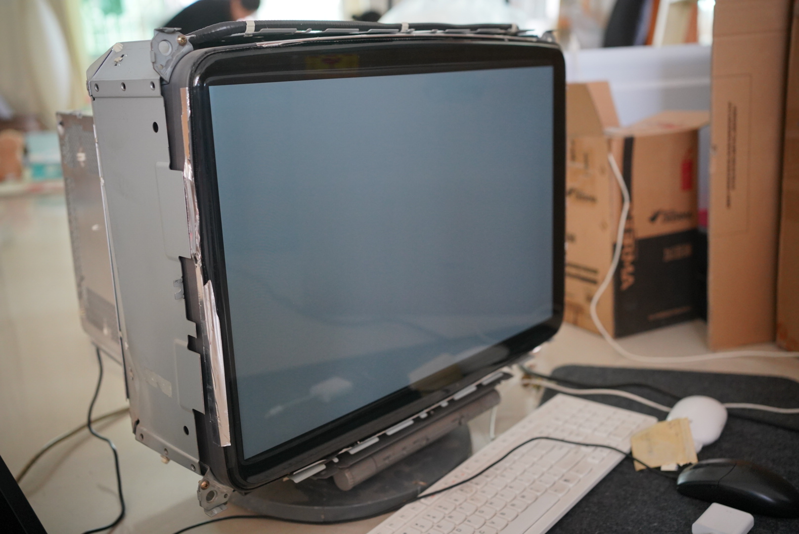
Selected patents
- U.S. patent 1,691,324: Zworykin Television System
External links
- "Cathode Ray Tube Monitors". PCTechGuide.
- "CRTs". Virtual Valve Museum.
- Goldwasser, Samuel M. (28 February 2006). "TV and Monitor CRT (Picture Tube) Information". repairfaq.org. Archived from the original on 26 September 2006.
- "The Cathode Ray Tube site". crtsite.com.