
Microwave transmission
This article needs additional citations for verification. (June 2012) |
Microwave transmission is the transmission of information or energy by microwave radio waves. Although an experimental 64 km (40 mile) microwave telecommunication link across the English Channel was demonstrated in 1931, the development of radar in World War II provided the technology for practical exploitation of microwave communication. In the 1950s, large transcontinental microwave relay networks, consisting of chains of repeater stations linked by line-of-sight beams of microwaves were built in Europe and America to relay long distance telephone traffic and television programs between cities. Communication satellites which transferred data between ground stations by microwaves took over much long distance traffic in the 1960s. In recent years there has been an explosive increase in use of the microwave spectrum by new telecommunication technologies such as wireless networks, and direct-broadcast satellites which broadcast television and radio directly into consumers' homes.
Uses
Microwaves are widely used for point-to-point communications because their small wavelength allows conveniently-sized antennas to direct them in narrow beams, which can be pointed directly at the receiving antenna. This allows nearby microwave equipment to use the same frequencies without interfering with each other, as lower frequency radio waves do. Another advantage is that the high frequency of microwaves gives the microwave band a very large information-carrying capacity; the microwave band has a bandwidth 30 times that of all the rest of the radio spectrum below it. A disadvantage is that microwaves are limited to line of sight propagation; they cannot pass around hills or mountains as lower frequency radio waves can.
Microwave radio transmission is commonly used in point-to-point communication systems on the surface of the Earth, in satellite communications, and in deep space radio communications. Other parts of the microwave radio band are used for radars, radio navigation systems, sensor systems, and radio astronomy.
The next higher part of the radio electromagnetic spectrum, where the frequencies are above 30 GHz and below 100 GHz, are called "millimeter waves" because their wavelengths are conveniently measured in millimeters, and their wavelengths range from 10 mm down to 3.0 mm (Higher frequency waves are smaller in wavelength).[clarification needed] Radio waves in this band are usually strongly attenuated by the Earthly atmosphere and particles contained in it, especially during wet weather. Also, in wide band of frequencies around 60 GHz, the radio waves are strongly attenuated by molecular oxygen in the atmosphere. The electronic technologies needed in the millimeter wave band are also much more difficult to utilize than those of the microwave band
Wireless transmission of information
- One-way (e.g. television broadcasting) and two-way telecommunication using communications satellite
- Terrestrial microwave relay links in telecommunications networks including backbone or backhaul carriers in cellular networks linking BTS-BSC and BSC-MSC.


Wireless transmission of power
- Proposed systems e.g. for connecting solar power collecting satellites to terrestrial power grids
Microwave radio relay

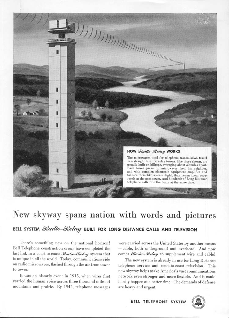
Microwave radio relay is a technology for transmitting digital and analog signals, such as long-distance telephone calls, television programs, and computer data, between two locations on a line of sight radio path. In microwave radio relay, microwaves are transmitted between the two locations with directional antennas, forming a fixed radio connection between the two points. The requirement of a line of sight limits the distance between stations. Precise distance between stations of a microwave link is a design decision based on path study analysis of terrain, altitude, economics of tower construction and required reliability of the link.
Beginning in the 1950s, networks of microwave relay links, such as the AT&T Long Lines system in the U.S., carried long distance telephone calls and television programs between cities.[1] The first system, dubbed TD-2 and built by AT&T, connected New York and Boston in 1947 with a series of eight radio relay stations.[1] These included long daisy-chained series of such links that traversed mountain ranges and spanned continents. Much of the transcontinental traffic is now carried by cheaper optical fibers and communication satellites, but microwave relay remains important for shorter distances.
Planning

Because the radio waves travel in narrow beams confined to a line-of-sight path from one antenna to the other, they don't interfere with other microwave equipment, so nearby microwave links can use the same frequencies, called frequency reuse. Antennas must be highly directional (high gain); these antennas are installed in elevated locations such as large radio towers in order to be able to transmit across long distances. Typical types of antenna used in radio relay link installations are parabolic antennas, dielectric lens, and horn-reflector antennas, which have a diameter of up to 4 meters. Highly directive antennas permit an economical use of the available frequency spectrum, despite long transmission distances.

Because of the high frequencies used, a line-of-sight path between the stations is required. Additionally, in order to avoid attenuation of the beam an area around the beam called the first Fresnel zone must be free from obstacles. Obstacles in the signal field cause unwanted attenuation. High mountain peak or ridge positions are often ideal

Obstacles, the curvature of the Earth, the geography of the area and reception issues arising from the use of nearby land (such as in manufacturing and forestry) are important issues to consider when planning radio links. In the planning process, it is essential that "path profiles" are produced, which provide information about the terrain and Fresnel zones affecting the transmission path. The presence of a water surface, such as a lake or river, along the path also must be taken into consideration as it can reflect the beam, and the direct and reflected beam can interfere at the receiving antenna, causing multipath fading. Multipath fades are usually deep only in a small spot and a narrow frequency band, so space and/or frequency diversity schemes can be applied to mitigate these effects.
The effects of atmospheric stratification cause the radio path to bend downward in a typical situation so a major distance is possible as the earth equivalent curvature increases from 6370 km to about 8500 km (a 4/3 equivalent radius effect). Rare events of temperature, humidity and pressure profile versus height, may produce large deviations and distortion of the propagation and affect transmission quality. High intensity rain and snow making rain fade must also be considered as an impairment factor, especially at frequencies above 10 GHz. All previous factors, collectively known as path loss, make it necessary to compute suitable power margins, in order to maintain the link operative for a high percentage of time, like the standard 99.99% or 99.999% used in 'carrier class' services of most telecommunication operators.
The longest microwave radio relay known up to date crosses the Red Sea with 360 km (200 mi) hop between Jebel Erba (2170m a.s.l., 28°44′46.17″N 36°50′24.65″E / 28.7461583°N 36.8401806°E, Sudan) and Jebel Dakka (2572m a.s.l., 21°5′36.89″N 40°17′29.80″E / 21.0935806°N 40.2916111°E, Saudi Arabia). The link was built in 1979 by Telettra to transmit 300 telephone channels and 1 TV signal, in the 2 GHz frequency band. (Hop distance is the distance between two microwave stations)[2]
Previous considerations represent typical problems characterizing terrestrial radio links using microwaves for the so-called backbone networks: hop lengths of few tens of kilometers (typically 10 to 60 km) were largely used until 1990s. Frequency bands below 10 GHz and, above all, the information to be transmitted was a stream containing a fixed capacity block. The target was to supply the requested availability for the whole block (Plesiochronous digital hierarchy, PDH, or Synchronous Digital Hierarchy, SDH). Fading and/or multipath affecting the link for short time period during the day had to be counteracted by the diversity architecture. During 1990s microwave radio links begun widely to be used for urban links in cellular network. Requirements regarding link distances changed to shorter hops (less than 10 km, typically 3 to 5 km) and frequency increased to bands between 11 and 43 GHz and more recently up to 86 GHz (E-band). Furthermore, link planning deals more with intense rainfall and less with multipath, so diversity schemes became less used. Another big change that occurred during the last decade was evolution towards packet radio transmission. Therefore, new countermeasures, such as adaptive modulation, have been adopted.
The emitted power is regulated by norms (EIRP) both for cellular system and microwave. These microwave transmissions use emitted power typically from 30 mW to 0,3 W, radiated by the parabolic antenna on a beam wide round few degrees (1 to 3-4). The microwave channel arrangement is regulated by International Telecommunication Union (ITU-R) or local regulations (ETSI, FCC). In the last decade the dedicated spectrum for each microwave band reaches an extreme overcrowding, forcing efforts towards techniques for increasing the transmission capacity (frequency reuse, Polarization-division multiplexing, XPIC, MIMO).

History

The history of radio relay communication began in 1898 from the publication by Johann Mattausch in Austrian Journal Zeitschrift für Electrotechnik (v. 16, 35 - 36)[3][4]. But his proposal was primitive and not suitable for use. The first relay system, which really functioned, was that invented in 1899 by Emile Guarini-Foresio.[3]
In 1931 an Anglo-French consortium headed by Andre C. Clavier demonstrated an experimental microwave relay link across the English Channel using 10 foot (3 m) dishes.[5] Telephony, telegraph and facsimile data was transmitted over the bidirectional 1.7 GHz beams 64 km (40 miles) between Dover, UK and Calais, France. The radiated power, produced by a miniature Barkhausen-Kurz tube located at the dish's focus, was one-half watt. A 1933 military microwave link between airports at St. Inglevert, UK and Lympne, France, a distance of 56 km (35 miles) was followed in 1935 by a 300 MHz telecommunication link, the first commercial microwave relay system.[6]
The development of radar during World War II provided much of the microwave technology which made practical microwave communication links possible, particularly the klystron oscillator and techniques of designing parabolic antennas. Though not commonly known, the US military used both portable and fixed-station microwave communications in the European Theater during World War II.
After the war telephone companies used this technology to build large microwave radio relay networks to carry long distance telephone calls. During the 1950s a unit of the US telephone carrier, AT&T Long Lines, built a transcontinental system of microwave relay links across the US that grew to carry the majority of US long distance telephone traffic, as well as television network signals.[7] The main motivation in 1946 to use microwave radio instead of cable was that a large capacity could be installed quickly and at less cost. It was expected at that time that the annual operating costs for microwave radio would be greater than for cable. There were two main reasons that a large capacity had to be introduced suddenly: Pent up demand for long distance telephone service, because of the hiatus during the war years, and the new medium of television, which needed more bandwidth than radio. The prototype was called TDX and was tested with a connection between New York City and Murray Hill, the location of Bell Laboratories in 1946. The TDX system was set up between New York and Boston in 1947. The TDX was upgraded to the TD2 system, which used [the Morton tube, 416B and later 416C, manufactured by Western electric ] in the transmitters, and then later to TD3 that used solid state electronics.
Military microwave relay systems continued to be used into the 1960s, when many of these systems were supplanted with tropospheric scatter or communication satellite systems. When the NATO military arm was formed, much of this existing equipment was transferred to communications groups. The typical communications systems used by NATO during that time period consisted of the technologies which had been developed for use by the telephone carrier entities in host countries. One example from the USA is the RCA CW-20A 1–2 GHz microwave relay system which utilized flexible UHF cable rather than the rigid waveguide required by higher frequency systems, making it ideal for tactical applications. The typical microwave relay installation or portable van had two radio systems (plus backup) connecting two line of sight sites. These radios would often carry 24 telephone channels frequency division multiplexed on the microwave carrier (i.e. Lenkurt 33C FDM). Any channel could be designated to carry up to 18 teletype communications instead. Similar systems from Germany and other member nations were also in use.
Long distance microwave relay networks were built in many countries until the 1980s when the technology lost its share of fixed operation to newer technologies such as fiber-optic cable and communication satellites, which offer lower cost per bit.

During the Cold War, the US intelligence agencies, such as the National Security Agency (NSA), were reportedly able to intercept Soviet microwave traffic using satellites such as Rhyolite.[8] Much of the beam of a microwave link passes the receiving antenna and radiates toward the horizon, into space. By positioning a geosynchronous satellite in the path of the beam, the microwave beam can be received.
At the turn of the century, microwave radio relay systems are being used increasingly in portable radio applications. The technology is particularly suited to this application because of lower operating costs, a more efficient infrastructure, and provision of direct hardware access to the portable radio operator.
Microwave link
A microwave link is a communications system that uses a beam of radio waves in the microwave frequency range to transmit video, audio, or data between two locations, which can be from just a few feet or meters to several miles or kilometers apart. Microwave links are commonly used by television broadcasters to transmit programmes across a country, for instance, or from an outside broadcast back to a studio.
Mobile units can be camera mounted, allowing cameras the freedom to move around without trailing cables. These are often seen on the touchlines of sports fields on Steadicam systems.
Properties of microwave links
- Involve line of sight (LOS) communication technology
- Affected greatly by environmental constraints, including rain fade
- Have very limited penetration capabilities through obstacles such as hills, buildings and trees
- Sensitive to high pollen count[citation needed]
- Signals can be degraded [citation needed]during Solar proton events[9]
Uses of microwave links
- In communications between satellites and base stations
- As backbone carriers for cellular systems
- In short range indoor communications
- Telecommunications, in linking remote and regional telephone exchanges to larger (main) exchanges without the need for copper/optical fibre lines.
- Measuring the intensity of rain between two locations
Troposcatter
Terrestrial microwave relay links are limited in distance to the visual horizon, a few tens of miles or kilometers depending on tower height. Tropospheric scatter ("troposcatter" or "scatter") was a technology developed in the 1950s allow microwave communication links beyond the horizon, to a range of several hundred kilometers. The transmitter radiates a beam of microwaves into the sky, at a shallow angle above the horizon toward the receiver. As the beam passes through the troposphere a small fraction of the microwave energy is scattered back toward the ground by water vapor and dust in the air. A sensitive receiver beyond the horizon picks up this reflected signal. Signal clarity obtained by this method depends on the weather and other factors, and as a result a high level of technical difficulty is involved in the creation of a reliable over horizon radio relay link. Troposcatter links are therefore only used in special circumstances where satellites and other long distance communication channels cannot be relied on, such as in military communications.
Microwave power transmission
Microwave power transmission (MPT) is the use of microwaves to transmit power through outer space or the atmosphere without the need for wires. It is a sub-type of the more general wireless energy transfer methods.
History
Following World War II, which saw the development of high-power microwave emitters known as cavity magnetrons, the idea of using microwaves to transmit power was researched. In 1964, William C. Brown demonstrated a miniature helicopter equipped with a combination antenna and rectifier device called a rectenna. The rectenna converted microwave power into electricity, allowing the helicopter to fly.[10] In principle, the rectenna is capable of very high conversion efficiencies - over 90% in optimal circumstances.
Most proposed MPT systems now usually include a phased array microwave transmitter. While these have lower efficiency levels they have the advantage of being electrically steered using no moving parts, and are easier to scale to the necessary levels that a practical MPT system requires.
Using microwave power transmission to deliver electricity to communities without having to build cable-based infrastructure is being studied at Grand Bassin on Reunion Island in the Indian Ocean.
Common safety concerns
The common reaction to microwave transmission is one of concern, as microwaves are generally perceived by the public as dangerous forms of radiation, stemming from the fact that they are used in microwave ovens.[citation needed] While high power microwaves can be painful and dangerous as in the United States Military's Active Denial System, MPT systems are generally proposed to have only low intensity at the rectenna.
Though this would be extremely safe as the power levels would be about equal to the leakage from a microwave oven, and only slightly more than a cell phone, the relatively diffuse microwave beam necessitates a large receiving antenna area for a significant amount of energy to be transmitted.
Research has involved exposing multiple generations of animals to microwave radiation of this or higher intensity, and no health issues have been found.[11]
Proposed uses
MPT is the most commonly proposed method for transferring energy to the surface of the Earth from solar power satellites or other in-orbit power sources. MPT is occasionally proposed for the power supply in beam-powered propulsion for orbital lift space ships. Even though lasers are more commonly proposed, their low efficiency in light generation and reception has led some designers to opt for microwave based systems.
Current status
Wireless power transmission (using microwaves) is well proven. Experiments in the tens of kilowatts have been performed at Goldstone in California in 1975[12][13][14] and more recently (1997) at Grand Bassin on Reunion Island.[15] In 2008 a long range transmission experiment successfully transmitted 20 watts 92 miles (148 km) from a mountain on Maui to the main island of Hawaii.[16]
JAXA announced on 12 March 2015 that they wirelessly beamed 1.8 kilowatts 50 meters to a small receiver by converting electricity to microwaves and then back to electricity. This is the standard plan for this type of power.[17][18] On 12 March 2015 Mitsubishi Heavy Industries demonstrated transmission of 10 kilowatts (kW) of power to a receiver unit located at a distance of 500 meters (m) away.[19]
See also
- Wireless energy transfer
- Fresnel zone
- Passive repeater
- Radio repeater
- Transmitter station
- Path loss
- British Telecom microwave network
- Trans-Canada Microwave
- Antenna array (electromagnetic)
References
- ^ a b Pond, Norman H. "The Tube Guys". Russ Cochran, Publisher, 2008 p.170
- ^ "Photos of Telettra". Facebook. Retrieved 2012-10-02.
- ^ a b
Slyusar, Vadym. (2015). "First Antennas for Relay Stations" (PDF). International Conference on Antenna Theory and Techniques, 21-24 April, 2015, Kharkiv, Ukraine. pp. Pp. 254 - 255.
{{cite web}}:|pages=has extra text (help) - ^ Mattausch J. Telegraphie ohne Draht. Eine Studie. // Zeitschrift für Elektrotechnik. Organ des Elektrotechnischen Vereines in Wien.- Heft 3, 16. Jänner 1898. - XVI. Jahrgang. - S. 35-36.[1]}}
- ^ Free, E. E. (August 1931). "Searchlight radio with the new 7 inch waves" (PDF). Radio News. 8 (2). New York: Radio Science Publications: 107–109. Retrieved March 24, 2015.
- ^ "Microwaves span the English Channel" (PDF). Short Wave Craft. 6 (5). New York: Popular Book Co.: 262 September 1935. Retrieved March 24, 2015.
- ^ "Sugar Scoop Antennas Capture Microwaves." Popular Mechanics, February 1985, p. 87, bottom of page.
- ^ James Bamford, The Shadow Factory, Doubleday, 2008, ISBN 0-385-52132-4. p.176
- ^ "Analyzing Microwave Spectra Collected by the Solar Radio Burst Locator". Digital.library.unt.edu. 2012-09-24. Retrieved 2012-10-02.
- ^ Brown, W. C. (Raytheon) (December 1965) "Experimental Airborne Microwave Supported Platform" Technical Report NO. RADC-TR- 65- 188, Air Force Systems Command. Retrieved July 9, 2012
- ^ "Environmental Effects - the SPS Microwave Beam". Permanent.com. Retrieved 2012-10-02.
- ^ "NASA Video, date/author unknown". Retrieved 2012-10-02.
- ^ "Wireless Power Transmission for Solar Power Satellite (SPS) (Second Draft by N. Shinohara), Space Solar Power Workshop, Georgia Institute of Technology" (PDF). Retrieved 2012-10-02.
- ^ Brown., W. C. (September 1984). "The History of Power Transmission by Radio Waves". Microwave Theory and Techniques, IEEE Transactions on (Volume: 32, Issue: 9 On page(s): 1230- 1242). Bibcode:1984ITMTT..32.1230B. doi:10.1109/TMTT.1984.1132833. ISSN 0018-9480.
{{cite journal}}:|issue=has extra text (help) - ^ POINT-TO-POINT WIRELESS POWER TRANSPORTATION IN REUNION ISLAND Archived October 23, 2005, at the Wayback Machine 48th International Astronautical Congress, Turin, Italy, 6–10 October 1997 - IAF-97-R.4.08 J. D. Lan Sun Luk, A. Celeste, P. Romanacce, L. Chane Kuang Sang, J. C. Gatina - University of La Réunion - Faculty of Science and Technology.
- ^ "Researchers Beam 'Space' Solar Power in Hawaii". Wired. 12 September 2008. Retrieved 28 May 2015.
- ^ Tarantola, Andrew (12 March 2015). "Scientists make strides in beaming solar power from space" (PDF). 162 (3856): 857–861.
{{cite journal}}: Cite journal requires|journal=(help) - ^ Japan space scientists make wireless energy breakthrough | Sci-Tech | thenews.com.pk
- ^ "MHI Successfully Completes Ground Demonstration Testing of Wireless Power Transmission Technology for SSPS". 12 March 2015.
- Microwave Radio Transmission Design Guide, Trevor Manning, Artech House, 1999
External links
- RF / Microwave Design at Oxford University
- AT&T's Microwave Radio-Relay Skyway introduced in 1951
- Bell System 1951 magazine ad for Microwave Radio-Relay systems.
- RCA vintage magazine ad for Microwave-Radio Relay equipment used for Western Union Telegraph Co.
- AT&T Long Lines Microwave Towers Remembered
- AT&T Long Lines
- IEEE Global History Network Microwave Link Networks
Radio spectrum (ITU) | |||||||||||||
|---|---|---|---|---|---|---|---|---|---|---|---|---|---|
| |||||||||||||
| |
| Gamma rays | |
| X-rays | |
| Ultraviolet | |
| Visible (optical) | |
| Infrared | |
| Microwaves | |
| Radio | |
| Wavelength types | |
