
Crosswind kite power: Difference between revisions
→Patents giving instruction on crosswind kite power: section title softening |
→Gallery: image add |
||
| Line 54: | Line 54: | ||
==Gallery== |
==Gallery== |
||
<gallery widths="640px" heights="384px"> |
<gallery widths="640px" heights="384px"> |
||
[[File:US3987987figs.JPG|thumb|US3987987figs]] |
|||
File:Kitegen.jpg|Crosswind kite power system with tether pull, drawing. |
File:Kitegen.jpg|Crosswind kite power system with tether pull, drawing. |
||
File:Crosswind_kite_power_station_with_fast_motion_transfer_having_two_wings_offshore.jpg|Crosswind kite power station with separate motion transfer with two wings offshore, artist's impression. |
File:Crosswind_kite_power_station_with_fast_motion_transfer_having_two_wings_offshore.jpg|Crosswind kite power station with separate motion transfer with two wings offshore, artist's impression. |
||
Revision as of 18:27, 28 June 2013
Crosswind kite power is power derived from a class of airborne wind-energy conversion systems (AWECS, aka. AWES) characterized by a kite system that has energy-gathering parts that fly crosswind; sometimes the entire wing set and tether set is flown crosswind. These systems at many scales from toy to power-grid-feeding sizes may be used as high-altitude wind power (HAWP) devices or low-altitude wind power (LAWP) devices without having to use towers. Flexible wings or rigid wings may be used in the kite system. A tethered wing, flying crosswind at many times wind speed, harvests wind power from an area that is many times exceeding the wing’s own area. Crosswind kite power systems have some advantages over conventional wind turbines: access to more powerful and stable wind resource, high capacity factor, capability for deployment on and offshore at comparable costs, and no need for a tower. Additionally, the crosswind kite may vary in aerodynamic efficiency; the movement of crosswinding tethered wings is sometimes compared with the outer parts of conventional wind turbine blades. However, a conventional rotating blade set carried aloft in a kite power system has the blade set cutting crosswind and is a form of crosswind kite power. Myles Loyd furthered studies on crosswind kite power systems in his work "Crosswind Kite Power" [1] in 1980. Some believe that crosswind kite power was introduced by P. Payne and C. McCutchen in their patent No. 3,987,987, filed in 1975[2], however, crosswind kite power was used far before such patent, e.g., in target kites for war-target practice where the crosswinding power permitted high speeds to give practice to gunners. [3]
Types

The three main types of crosswind kite power systems are distinguished by the method of the power removal from the wing: an onboard generator, a tether lift and fast motion transfer.
Tether pulling
In the systems of this type, an electrical generator, pump, or tasking line is installed on the ground. There are two subtypes, with or without a secondary vehicle. In the subtype without a secondary vehicle,"Yo-Yo" method, the tether slowly unwinds off a drum on the ground, due to the windward pull of the kite system's wing, while the wing travels crosswind, that is, left-right of the wind's ambient direction, along various paths, e.g., a figure-8 flight path, or optimized lemniscate paths, or circular paths (small or large radius). The turning drum rotates the rotor of the generator or pump through, perhaps, a high-ratio gearbox. Periodically, the wing is depowered, and the tether is reeled in, or, using the crosswind for a constant pull, the tether is re-connected to a different section of the drum while the wing is traveling in a "downwind" cycle. In some systems two tethers are used instead of one. [1]
In another subtype, a secondary vehicle is used. Such a vehicle can be a carousel, a car, railed cart, wheeled land vehicle, or even a ship on the water. The electrical generator is installed on the vehicle. The rotor of the electrical generator is brought in motion by the carousel, the axle of the car, or the screw of the ship, correspondingly. [4]
Onboard generator
In the systems of this type, one or more propellers and electrical generators are installed on the wing. The relative airflow rotates the propellers, which transfer the power to the generators. Produced electrical energy is transmitted to the ground through an electrical cable laid along the tether [1] or integrated with the tether.
Fast motion transfer
In this type, an electrical generator is installed on the ground and a separate cable or belt, trailing behind the wing, transfers the power to a sprocket on the ground, which rotates the rotor of the generator. The separate belt extends at approximately the speed of the wing. Because of the high speed of that belt, the gearbox is not required. [5]
Theory
In all types of the crosswind kite power system, the useful power can be approximately described by the Loyd’s formula:

where P is power; CL and CD are coefficients of lift and drag, respectively; ρa is the air density at the altitude of the wing; A is the wing area and V is the wind speed [1]. This formula disregards tether drag, wing and tether weights, change of the air density with altitude and angle of the wing motion vector to the plane, perpendicular to the wind. A more precise formula is:

where G is the effective gliding ratio, taking into account the tether drag. [6]
Example: a system with a rigid wing, having dimensions 50m x 2m and G=15 in the 12 m/s wind will provide 40MW of electric power.
Challenges
One traction leader Skysails used for ship propulsion in a manner similar to traditional sails. Some of the challenges that crosswind kite power systems must overcome to achieve mainstream acceptance are: regulatory permissions, including use of airspace and land; safety considerations; reliable operation in varying conditions (day, night, summer, winter, fog, high wind, low wind, etc.); third-party assessment and certification; lifecycle cost modeling [7].
History and prospects
Crosswind kite power was brought again into focus when Loyd carefully described it in 1980. It was not possible to create an economical automatic control system to control the wing, though passive control of crosswinding kite systems has been ancient. This has changed in the passing years, when computational and sensory resources became not only affordable, but cheap. In the same time, significant progress was made in the materials and wing construction techniques. New types of flexible kites with good L/D ratio have been invented. Synthetic materials, suitable for the wing and tether, became affordable. Among those materials are UHMWPE, carbon fiber, PETE, and rip-stop nylon. A large number of people became engaged in the sports of kitesurfing, kiteboarding, kite buggying, snowkiting, and power kiting. Multiple companies and academic teams work on crosswind kite power. Most of the progress in the field has been achieved in the last 10 years. In May 2013 Google acquired a Californian company developing systems with onboard generators [8].
Patents that involve crosswind kite power
The are two sectors of crosswind kite power patents, those that have placed some technology into the public domain and those that are within protection periods and perhaps have valid claims. Crosswind kite power teachings in each patent are part of what is reviewed by the crosswind kite power research and development community and interested readers.
- US 3987987 Self-erecting windmill by Charles McCutchen and Peter R. Payne. They filed in January 28, 1975. Their work is now in the public domain.
- US8066225 Multi-tether cross-wind kite power. Benjamin Tigner filed in Jan 19, 2009, but has a priority date of Jan. 31, 2008. He teaches crosswind kite farming to make electricity.
- US6781254 Windmill kite by Bryan William Roberts with priority date of Nov 7, 2001. This examples crosswind kite power using flying generators driven by autorotating crosswinding turbine blades which play a second roll of being driven by costing power to fly the aircraft to altitude or bring the aircraft to safe harbor. The fast motion of the crosswinding blades is mined to drive the airborne wind generators at the hub of the rotating blades. This type of machine was featured in Popular Science magazine.[9]
Scale of crosswind kite power systems
Crosswind kite power systems are found in toy power kites, sport power kites , and experimental-handy sizes; proposed by research centers are huge utility-grid-power-feeding sizes. The power gained in toy sizes is used to excite product users; two-line and four-line crosswind toy kite-power systems fill kite festival skies. Serious sport crosswind kite power systems drive the movement of athletes around race courses in local and national competitions. Experimental-handy sizes of crosswind kite power systems are explored while furthering research toward utility-scale systems.
Timeline of uses and progress of crosswind kite power
Crosswind kite power has been put to various uses throughout history. And the variety of devices that produce crosswind kite power have a historical progression. A simple kite system sitting passively without crosswind kite power production is contrasted with kite systems that fly crosswind producing greater harvesting of energy from the wind's kinetic energy. For perspective, a timeline of crosswind kite power uses and device progress may aid in understanding crosswind kite power.
- Crosswind kite power used in military target practice by Paul Garber.[10] The gained crosswind kite power was used to produce speed of the target wing to simulate enemy aircraft.
Gallery
-
Crosswind kite power system with tether pull, drawing.
-
 Crosswind kite power station with separate motion transfer with two wings offshore, artist's impression.
 -
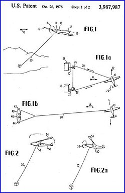 Drawing from patent US 3,987,987.


References
- ^ a b c d M. Loyd, "Crosswind Kite Power", J. Energy, vol. 4, no. 3, pp. 106-111, 1980
- ^ Peter R. Payne, inventor, Self-erecting windmill, [1]
- ^ http://robroy.dyndns.info/targetkites/
- ^ J. Kim, C. Park, "Wind power generation with a parawing on ships, a proposal", Energy, Int. J, vol. 35, p. 1425–1432, 2010.
- ^ L. Goldstein, "Theoretical analysis of an airborne wind energy conversion system with a ground generator and fast motion transfer", Energy, Int. J, 2013.
- ^ B. Houska, M. Diehl, "Optimal Control of Towing Kites", in Proceedings of the 45th IEEE Conference on Decision and Control, San Diego, US, 2006.
- ^ F.Felker "Engineering Challenges of Airborne Wind Technology"
- ^ http://www.businessweek.com/articles/2013-05-22/inside-googles-secret-lab
- ^ [2]
- ^ http://www.drachen.org/collections/original-paul-garber-target-kite-training-video-us-navy
See also
- Airborne wind turbine
- High-altitude wind power
- Unconventional wind turbines
- Stakeholders in Crosswind kite power