
FS Class E.636
| FS class E636 | |||||||||||||||||||||||
|---|---|---|---|---|---|---|---|---|---|---|---|---|---|---|---|---|---|---|---|---|---|---|---|
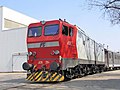
 E636-002 in its original livery, property of FerAlp Team museum in Bussoleno | |||||||||||||||||||||||
| |||||||||||||||||||||||
| |||||||||||||||||||||||
| |||||||||||||||||||||||
| |||||||||||||||||||||||
The FS E636 is a class of Italian railways articulated electric locomotives. They were introduced in the course of the 1940s until the 1960s, and have been decommissioned in 2006. They have been one of the most numerous Italian locomotive group, and have been widely employed during their career.
History

The E636 were designed to overcome the problems showed in the 1930s by both the E626 multi-purpose and E326 high-speed locomotives, in order to better handle the increasing railway traffic in Italy.
The E636 was the first Italian locomotive adopting the Bo-Bo-Bo configuration with chassis divided into two articulated parts pivoting on the central bogie, which were repeated on the E645/646 and E656 classes. The presence of a great number of wheels was considered important due of the presence of a number of high-slope lines in the Italian railroad network. The new engines weighted approximately 101 tons. Engines were initially the same as E626. The 32R used a 3kV catenary but this was soon shown to be inadequate and so were updated and provided with a new hollow axle transmission system. Mainly two different gear ratios were installed: 21/65 for sloping lines or heavy freight trains (maximum speed of 95 km/h, elevated later to 110 km/h), and the longer 28/65, with a maximum speed of 120 km/h, suited for passenger services.
The locomotive was built in three different series:
- 1st series (001-108), from 1940 to 1942
- 2nd series (109-243), from 1952 to 1956
- 3rd series (001-008), from 1957 to 1962
The first unit entered service in the May 1940. Six locomotives were destroyed during World War II. After the war the total number of locomotives were brought to 469, also thanks to the support from Marshall Plan, and making it one of the most numerous groups of Italian locomotives. All the units were painted with an auburn livery; this was changed in the 1990s to a white one with green stripes for most trains (XMPR livery).
As for 2000s railway standards, E636s were old and uncomfortable. The original design of the cockpits proved aboslutely unfit to modern safety standards: this was shown in an accident in 1996 at Sulmona, where the engine driver died despite the low speed, without being able to leave the cockpit in time. 200 units were therefore rebuilt and stripped of all asbestos.
Starting from 1990s, E636 were used mainly for cargo services, save for the more backlog Sicilian lines. Some units were lent to minor Italian railroads. The phasing out of the entire class was completed in May 2006.
Technique
E636 are very simple locomotives. Most functions of the main command circuit are accomplished through various relays and contactors. In case of failure the train driver could easily fix them to at least free the tracks; also, in recent times, E636s were the first locomotives that the new train drivers studied during their training courses, due to their simple working mechanics.
Motors & electrical description
As most older Italian locomotives, E636 has a rheostat (formed by 16 cast iron resistors connected in series, for a total resistance of 29 ohms) that needs to be gradually, but as soon as possible, excluded on start-ups, which regulates the flow of current to the six 32R-200 DC traction motors, 2 per bogie.
The motors can be connected in three combinations: series, series-parallel and parallel; each combination provides a progressively higher voltage to the motors, therefore increasing the current.
Their set-up is the following:
| Combination | Motor set-up | Voltage per motor |
|---|---|---|
| Series | All motors are connected in series | 500 V |
| Series-Parallel | Two branches of three motors | 1000 V |
| Parallel | Three branches of two motors | 1500 V |

The rheostat (connected in series to the traction motors) is necessary because the DC motor has the intrinsic characteristic of absorbing a current inversely proportional to its rotating speed; at high speeds, it absorbs less current. This means that on start the current would be very high, because the only resistance encountered would be only the one offered by motors and internal conductors, wich is very low (a short circuit, in practice). The rheostat highers the overall resistance when starting the locomotive, lowering the current and allowing a smoother start.
In S-P and P combinations, the rheostat is divided in three branches connected in parallel; this lowers the overall rheostat equivalent resistance to about 3,5 ohm, while in S combination its elements are all connected in series.
Like almost every Italian locomotive with rheostatic regulation since E626, traction is controlled via a lever (commonly referred to as "maniglione") mounted on a support called roncola; this support has several notches, each representing a portion of the rheostat, plus three "end combination" notches. To accelerate, the driver rotates gradually counterclockwise the lever notch by notch, and in doing so the various rheostat contactors are closed, shunting the resistors and lowering the total rheostat resistance, also allowing more current to flow to the motors; as speed builds up, the counter-electromotive force lowers this current, until the rheostat is no longer necessary: it is, then, totally excluded (obviously if in traction and in an "end combination" notch). This safely allows traction for an indefinite period of time, within certain limits.
When the end combination notches are reached, the driver can then insert the single shunt (one for each combination) or make a transition to the next combination, reintroducing the rheostat which has to be excluded again, until the end of parallel combination is reached. The shunts increase the current flowing into the motors by shunting some motor spires (through a contactor in parallel); this reduces the magnetic flux and, as said, increases the current (since the two are inversely proportional). There are various "shunt levels", depending on the locomotive, as is further explained; usually, there is one per combination. It is also important to remove the shunts before making a transition, in order to avoid flashes due to anormally high currents.
Like some E626s, E636 locomotives don't have the CEM "motor combiner" (CEM stands for Combinatore Escluditore Motori), a device that, during transitions, rotates, combining the motors accordingly through various contactors.
On 636, this is achieved through the uses of more delicate spires, so transitions (especially backward ones) need to be very slow and gradual. The optimal moment to pass to the following/preceding combination is when the motor ammeter indicates 0 Ampères, when standing over the end combination notch with the lever, meaning that the motor contactors are in optimal position and is safe to proceed. Failure in doing this may result in flashes that will damage the contactors.
An important parameter the driver has to consider, especially during rheostatic exclusion, is the current flowing into the traction circuit.
In particular, if he is excluding too fast, a wheel slippage can occur (in this case the use of sanders and reducing throttle can help), and one or more maximum current relays can open when the maximum allowed current value is exceeded.
The locomotive is protected from overly high currents through different kinds of relays:
- General maximum current relay (RMx);
- Three motor branch (Ramo Motori) maximum current relays (RMx 1-2, RMx 3-4, RMx 5-6);
- REC (Riscaldamento Elettrico Carrozze, is the electrical system used to provide the 3000 V coaches' electrical heating) maximum current relay (RMx REC);
Before the 70s, the maximum currents for the relays where the following:
| Relay | Maximum Current allowed |
|---|---|
| RMx | 1050 A |
| RMx 1-2 | 450 A |
| RMx 2-3 | 350 A |
| RMx 3-4 | 350 A |
| RMx REC | 500 A |
Between 1970 and 1980, the previous values changed:

| Relay | Maximum Current allowed |
|---|---|
| RMx | 1200 A |
| RMx 1-2 | 450 A |
| RMx 2-3 | 400 A |
| RMx 3-4 | 400 A |
| RMx REC | 500 A |
As can be seen, the currents allowed in series are 450 A in both cases, while in Series-Parallel and Parallel combinations are 350 A and 450 A respectively.
As said, one level of field shunt (percentage of field weakening: 31%) is allowed in each combination; however, some units received 92-250 (used on FS Class E424) and 32RT-200 type motors which allowed a maximum of 5 levels of field shunts (percentage of field weakening: 65%, 45% on the latters). These units where later made identical to standard ones again.
Motion transmission
Units from 001 to 243 mounted Negri-type transmission, except for units 195-198 and 176-183 which had a rubber tampons in place of coil packs and double hollow axle transmission and rubber tampons respectively.
All the following built units had the same transmission type of 176-183 but slightly different.
Different locomotives have received various gear ratios (see "Special Units" for more details):
| Gear ratio | Max speed (km/h) | Notes |
|---|---|---|
| 21/65 | 110 | Originally 95 km/h elevated to 105 km/h shortly after, then to 110 in 1982 |
| 28/65 | 120 | Eliminated in year 1991 |
| 20/65 | 120 | Units 044 and 089 only |
| 24/74 | 105 | Units 271-275 only |
Auxiliary and pneumatic services
The motor cooling-fans were activated by two 4.5 kW 3000 V dedicated motors until unit 201; later units have 1 kW motors identical to the ones used on FS Class E646; they are also used as dynamos to recharge the 24 V batteries (only if line voltage is greater than 1500 V) used to feed low tension devices (lights, locomotive heating systems, contactors etc.)
Air production on the locomotive was granted by two C38 type compressors; later they were upgraded with the more reliable W242, however, on some units, only one compressor was replaced, leaving one of each type in use on a single locomotive; the C38 produced air until 8 bars in main reservoir tanks were reached, while the W242 from 8 to 9 bars. In fact, on these units, only the W242 was used on normal conditions; the other one only if pressure dropped below 7 bars.
Main-tanks and the 24 V batteries supplies air and current to several systems:
- Braking system tanks.
Two tanks, called "Serbatoio di comando" and "Serbatoio ausiliario"; they take air from the main reservoir tanks and are kept under a pressure of 5 bar (when brakes are unreleased).
- Main breaker (interruttore rapido, IR)
It is the "high voltage switch" that connects the 3 kV of the line to the locomotive. It can be closed only when pressure is greater than 5 bars.
- Contactors
Contactors are widely employed on Italian electro-mechanic locomotives, including E636. They are used in various systems, mainly to insert/exclude the rheostat's resistors; can move only when pressure is greater than 5 bars, and the IR must be closed.
- Horn & whistle (Tromba and Fischio)
The locomotives have two horns and whistles, one above each driving cab. The firsts are activated by a solenoid valve and work only when batteries are inserted and pressure is greater than 5 bars, while the seconds can reach their maximum frequence with pressures of about 4 bars.
- Sand throwers (Sabbiere)
Sandthrowers, like the name suggests, throw sand on the track, in order to increase adherence. They are to be manually activated by the driver in case of wheel-slip, and work with pressure of about 5 bars.
- Flange oilers (Ungibordo)
During the 1970s, in order to conserve the wheel flange, the locomotives have received a DeLimon system that sprays oil via compressed air on regular selectable intervals into the channel between wheel flange and wheel surface of the front wheel.
- First pantograph-raise compressor (Compressore di primo alzamento)
This small compressor, feed by the 24 V provided by the batteries is used when first activating the locomotive, when main tanks are empty, to produce enough air to raise the pantograph for the first time.
Originally the locomotive mounted a 7-positions L-type Westinghouse brake controller and wheel-type locomotive brake, later replaced by the more common Oerlikon FV4 and RA-M2 levers respectively.
Braking systems


The locomotive has three kinds of brakes:
- Hand brake: manually activated by two wheels in each cab, one for each bogie, which make the brake shoes clamp against the wheel; a total of four out of six axles are braked this way.
- Locomotive air brakes: takes air from the main reservoir tanks, bypassing the brake pipe and directly loading the brake cylinders of the locomotive, thus braking it.
- Continuous, automatic air brake, used to brake the entire train.
It is a negative-type brake and is called continuous because it extends itself through the entire train, automatic because if brake continuity is no longer present (general pipe breaks), emergency braking is automatically applied.
On units with Breda-type valves and Oerlikon levers the brakes are graduable during braking and releasing; the working principles are the following.
The braking system is formed by two kind of tanks, called "auxiliary reservoir" (serbatoio ausiliario, present on every kind of stock) and "command reservoir" (serbatoio di comando, present only on locomotives and driving coaches), one or two pipes, running along the train, called "main pipe" (condotta principale, only on passenger stock) and "general pipe" (condotta generale, the actual brake pipe), plus the brake rigging; when brakes are released, pressure in the system is 5 bars, and 0 bars in brake cylinders.
- To brake the train, the train driver, via the brake controller, creates a depression in the command reservoir, which makes the general pipe to gradually lower its pressure to a value equal to the one present in the command reservoir (how fast this happens depends on train length: the longer it is, the slower this procedure will be); the auxiliary reservoir tanks then "hear" this pressure variation and empty themselves until they reach the pipe pressure, sending a quantity of air to the brake cylinders proportional to the entity of the depression. The maximum pressure that can be reached into the brake cylinders on E636 is 3,8 bar, which corresponds to a pressure inside the general pipe of about 3,5 bars.
In case of emergency braking, the brake pipe is put to direct communication with outside atmosphere, rapidly dropping pressure, and consequently making the train brake very fastly.
- To release brakes, the driver makes the pressure rise in the command reservoir via the brake controller; the pressure in the brake pipe is restored (air is taken from the main reservoir tanks, and from the main pipe if present) to the value present in the command reservoir, as is done into the auxiliary tanks; the brake cylinders unload themselves sending their air outside until their pressure reaches a value proportional to the entity of the depression.
For a faster brakes' release, it is also possible to briefly "overload" the general pipe to a pressure proportional to the depression previously present, up to a maximum pressure of 7.2 bars; shortly after this, pipe pressure drops to 5.5 bars, and is gradually brought back to 5 bars in about 240 secs.
However, on units with Triple Valves (Distributore tipo Westinghouse) and 7-positions levers, braking circuit is slightly different, and braking is not gradual on release: when the driver puts the controller on "release" position, brakes are fully released; if he brakes again too shortly after, there is the risk to have a loss of braking power, because there may not be enough air to brake optimally, or even exhaust the reservoir, with the consequent danger to not be able to stop the train. This is prevented in units with Breda valves as the brakes cannot be fully released if there is not enough air in main reservoir tanks to brake again.
Mechanical modifies
The locomotive is formed by two half carbodies, pivoting over the central bogie. Between them, there is a bellow, which was originally made with rubber then replaced in the 1950s by an impermeable membrane. In recent years this was further replaced by flexible plastic material.

On post war units, 7 mm. reinforcement frames have been introduced on the chassis and under the cabs, as the first 108 units showed some mechanical weaknesses in those points; in mid 1980s it was decided to reinforce only the chassis on pre-war units (however units 026 an 065 never received these modifications).
To reduce parasite motion, dampers were mounted between the carbodies: glycerine-type from units 1-276 and special-oil type from unit 277 onwards, although these were later eliminated in 1977 because considered useless.
The first 108 units had different rheostat ventilation shafts on the roof than the rest of the units ones, although these were later replaced with the more efficient shafts used on the latters.
They also had sliding oil-buckles, while following units had rolling bearing ones.
Units 162-171 were equipped with French-derived Athermos buckles for testing purposes, which were later removed.
Sandthrowers were mounted internally into the bogie in the units 001 - 108; after the war they were replaced by external ones that also were natively mounted on later units.
Safety systems
The first 108 locomotives originally had mounted a vigilance pedal designed by FS engineer Minucciani, that required a periodic acknowledgement from the driver when the train was moving (or emergency braking would have been commanded), but after the war, due to labor union pressures, it was discontinued; however, starting from the 1970s, many (not all) units received "Ripetizione Segnali a 4 codici" system, Hasler speedometer and a modified "speed graph recorder" (Zona tachigrafica), that also recorded the codes received from the RS.
Special units & experiments
- E636-385 was part of the "PV Train" project and received photovoltaic cells used to recharge the 24 V batteries. Due to this, it has been inserted in the asset of Italian historical units;
- E636-082 has been used for testing in 1965 of rheostatic braking (the same system was later adopted on FS Class E444); a second, smaller lever was mounted on the top of the traction lever, and was used to control the braking rheostat. This units also mounted more and bigger vents on its sides. At this time, it has been stripped of many internal components, and is not able to run.
- E636-284 is maybe the most famous unit of the group. The unit was involved in an accident, where the driving cabin was damaged. FS decided to recover the unit, and also decided to experiment a new type of driving cabin, similar to the ones used on FS class E656. The unit is nicknamed "Camilla", originating from which is supposed to be the girlfriend's name of a worker employed in the rebuilding works, who wrote it with chalk near one of the couplers of the locomotive (http://www.e636.it/284_2.jpg). This unit is also historical.
- In 1951 units 044 and 089 received the 92-250 type motors, used on FS Class E424, and the gear ratio was also changed to 20/65, for a maximum speed allowed of 120 km/h (max power 2490 kW instead of 2100 kW). The results of this experiment had proven successful, as these locomotives had the same performances as FS Class E428 (gear ratio 31/101), but with less weight and power; however they were later brought back to their original status.
- Units from 271 to 275 where built with different bogies than the standard ones (similar to the ones used on the FS Class E646 prototypes), 32RT-200 motors, 5 shunt levels and a gear ratio of 24/74 (max speed 105 km/h). These units were later made identical to standard units.
During the 60s - 70s Ansaldo-Breda built a locomotive derived from E636 for use in Yugoslavia, classified JZ 326.
-
 E636-284 "Camilla" in Milano Smistamento
 -
 E636 PVT (Photovoltaic Train)


References
- Istruzione sull'Esercizio del Freno Continuo Automatico
- Giovanni Cornolò (1994). Locomotive Elettriche.
{{cite book}}: Cite has empty unknown parameter:|1=(help) - Some parts have been translated from the article present on the Italian Wikipedia.