
Spoke
A spoke is one of some number of rods radiating from the center of a wheel (the hub where the axle connects), connecting the hub with the round traction surface.


The term originally referred to portions of a log that had been split lengthwise into four or six sections. The radial members of a wagon wheel were made by carving a spoke (from a log) into their finished shape. A spokeshave is a tool originally developed for this purpose. Eventually, the term spoke was more commonly applied to the finished product of the wheelwright's work, than to the materials he used.
History
The spoked wheel was invented to allow the construction of lighter and swifter vehicles. The earliest known examples are in the context of the Andronovo culture, dating to ca. 2000 BC. Soon after this, horse cultures of the Caucasus region used horse-drawn spoked-wheel war chariots for the greater part of three centuries. They moved deep into the Greek peninsula where they joined with the existing Mediterranean peoples to give rise, eventually, to classical Greece after the breaking of Minoan dominance and consolidations led by pre-classical Sparta and Athens. Celtic chariots introduced an iron rim around the wheel in the 1st millennium BC. The spoked wheel was in continued use without major modification until the 1870s, when wire wheels and rubber tires were invented.[1]
Construction
Spokes can be made of wood, metal, or synthetic fiber depending on whether they will be in tension or compression.
Compression spokes
The original type of spoked wheel with wooden spokes was used for horse-drawn carriages and wagons. In early motor cars, wooden spoked wheels of the artillery type were normally used.
In a simple wooden wheel, a load on the hub causes the wheel rim to flatten slightly against the ground as the lowermost wooden spoke shortens and compresses. The other wooden spokes show no significant change.
Wooden spokes are mounted radially. They are also dished, usually to the outside of the vehicle, to prevent wobbling. Also, the dishing allows the wheel to compensate for expansion of the spokes due to absorbed moisture by dishing more.[2]
Tension spokes
For use in bicycles, heavy wooden-spoked wheels were replaced by lighter wheels with spokes made of tensioned, adjustable metal wires, called wire wheels. These are also used in wheelchairs, motorcycles, and automobiles.
Types
Some types of wheels have removable spokes that can be replaced individually if they break or bend. These include bicycle and wheelchair wheels. High quality bicycles with conventional wheels use spokes of stainless steel, while cheaper bicycles may use galvanized (also called "rustless") or chrome plated spokes. While a good quality spoke is capable of supporting about 225 kgf (c. 500 pounds-force or 2,200 newtons) of tension, they are used at a fraction of this load to avoid suffering fatigue failures. Since bicycle and wheelchair wheel spokes are only in tension, flexible and strong materials such as synthetic fibers, are also occasionally used.[3] Metal spokes can also be ovalized or bladed to reduce aerodynamic drag, and butted (double or even triple) to reduce weight while maintaining strength.
A variation on the wire-spoked wheel was Tioga's "Tension Disk", which appeared superficially to be a solid disk but was in fact constructed using the same principles as a normal tension-spoked wheel. Instead of individual wire spokes, a continuous thread of Kevlar (aramid) was used to lace the hub to the rim under high tension. The threads were encased in a translucent disk for protection and some aerodynamic benefit, but this was not a structural component.
| wire gauge | diameter | section area |
|---|---|---|
| 15G | 1.8 mm | 3.24 mm² |
| 14G | 2.0 mm | 4 mm² |
| 13G | 2.3 mm | 5.29 mm² |
| 12G | 2.6 mm | 6.76 mm² |
| 11G | 2.9 mm | 8.41 mm² |
| 10G | 3.2 mm | 10.24 mm² |
Reaction to load

Wire wheels, wire-spoked wheels, tension-spoked wheels, or "suspension" wheels are wheels whose rims connect to their hubs by wire spokes.[5][6][7] Although these wires are considerably stiffer than a similar diameter wire rope, they function mechanically the same as tensioned flexible wires, keeping the rim true while supporting applied loads. The term suspension wheel should not be confused with vehicle suspension.[7]
Wire wheels are used on most bicycles and are still used on many motorcycles. They were invented by aeronautical engineer George Cayley in 1808.[8] Although Cayley first proposed wire wheels, he did not apply for a patent. The first patent for wire wheels was issued to Theodore Jones of London, England on October 11, 1826.[9] Eugène Meyer of Paris, France was the first person to receive, in 1869, a patent for wire wheels on bicycles.[10]
Bicycle wheels were not strong enough for cars until the development of tangentially spoked wheels. They rapidly became well established in the bicycle and motor tricycle world but were not common on cars until around 1907. This was encouraged by the Rudge-Whitworth patented detachable and interchangeable wheels designed by John Pugh. These wheels owed their resistance to braking and accelerative stresses to their two inner rows of tangential spokes. An outer row of radial spokes gave lateral strength against cornering stresses. These wheels were deeply dished so that steering pivot pins might lie as near as possible to the center-line of the tires. Their second feature was that they were easily detachable being mounted on splined false hubs. A process of assembling wire wheels is described as wheelbuilding.
On automobiles
This section needs additional citations for verification. (June 2013) |
From the earliest days automobiles used either wire wheels or heavy wooden or pressed steel spoked artillery type. The development of the quick detachable hubs of either Rudge-Whitworth or Riley design did much to popularise wire wheels and incidentally led to the fitting of "spare wheels". After their wooden spoked artillery wheels proved inadequate many US manufacturers paid John Pugh of Rudge-Whitworth royalties to manufacture wire wheels using his patents. Artillery wheels fell out of favour in the late 1920s and the development of the cheaper pressed steel wheels by Joseph Sankey replaced wire wheels wherever the premium price of wire wheels was not justified by their weight saving.
- A sample of automobile wire wheels
-
-

-

-

-

-
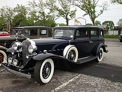
 Rolls-Royce Phantom III 1937 high-quality centre-lock (wire) wheels streamlined by nave plates
 -
 Wire wheels on a 1929 Alfa Romeo 6C 1750 Spyder Supersport
 -
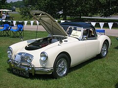 Wire wheels on a 1957 MGA
 -
 Rudge-Whitworth wire wheel on a 1922 Vauxhall 25


.JPG)


_(cropped).jpg)


Sports cars
Before 1960, sports/racing cars usually had Rudge-Whitworth centerlock wire wheels equipped with splined hubs and a quick-release "knockoff" (central wing nut) locking cap[11] that could be unscrewed by striking a wing of the nut with a special alloy mallet or "knockoff hammer".[12] Some jurisdictions, including the United States and West Germany, prohibited eared hubcaps for safety reasons in the late 1960s. In response, some manufacturers (e.g. Maserati) preferred to hold the wheel on the splined hub by capping with a single conventional unwinged hex nut requiring a special large spanner.[13]
In the 1960s, even lighter cast alloy wheels became usual—at first with splined hubs and knock-off caps—and now predominate. New versions of wire wheels are still made but often with standard hub bolt patterns covered by a center cap to fit without adapters.
- Wire wheels on sportscars
-
 Wire hubcaps mimicking real wire wheels on a 1989 Cadillac Brougham
 -


.jpg)
On motorcycles
At one time, motorcycles used wire wheels built up from separate components, but, except for adventure, enduro or dirtbikes, they are now mainly used for their retro appearance.
- Motorcycles with wire wheels
-
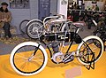
 Wire wheels on a 1906 Curtiss V-8 motorcycle
 -
![Wire wheels on a French San Sou Pap motorcycle[14]](//upload.wikimedia.org/wikipedia/commons/thumb/8/85/Sans_sou_pap.jpg/120px-Sans_sou_pap.jpg) Wire wheels on a French San Sou Pap motorcycle[14]
Wire wheels on a French San Sou Pap motorcycle[14] -
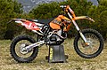
 Wire wheels on a modern motocross-style motorcycle
 -
 Wire wheels on a modern enduro-style motorcycle
 -
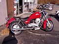 Wire wheels on a modern cruiser-style motorcycle
 -
 Wire wheels on the first Harley-Davidson motorcycle

![Wire wheels on a French San Sou Pap motorcycle[14]](/wiki/File:Sans_sou_pap.jpg)


On bicycles
The first commercially successful use of wired wheels was on bicycles. They were introduced early on in the development of the bicycle, following soon after the adoption of solid rubber tires. This development marked a major improvement over the older wooden wheels, both in terms of weight and comfort (the increased elasticity of the wheel helping to absorb road vibrations).[15]
In England, the engineer William Stanley developed the steel-wired spider wheel in 1849, an improvement over the cumbersome wooden spoked wheels then fitted to the tricycles that his employer was making.[16][17][18]
Bicycle manufacturers build millions of wheels annually, using the common crossed-spoke patterns whose crossings of adjacent spokes are governed by the number of spokes in the wheel. Wheelbuilders of racing teams and in good bicycle shops build wheels to other patterns such as two-cross, one-cross, or no-cross (usually called radial). Many of these patterns have been used for more than 100 years. It is claimed that crossed patterns have more strength and stability, and that irregular patterns are art forms and have little structural merit.[19]
In the 1980s, cast wheels with 5 or 6 rigid spokes began to appear in the Olympic Games and in professional racing. These have advantages in specialized applications, such as time trials, but wire-spoked wheels are used for most purposes.
Spoke tension and tire pressure
Typically, each spoke is pretensioned to about 100 pounds of force, on an unloaded wheel. When the bicycle is loaded with a rider, then the spokes below the hub have less tension. With every rotation of the wheel, there is repeatedly changes in the spoke tension that can contribute to broken spokes because of fatigue failures. Fatigue usually causes spokes to fail.[20]
With the proper air pressure, the tire will absorb light bumps and vibrations and roll faster than a hard, inflexible tire at higher air pressures in the 120-130 psig range. Heavier riders require slightly higher air pressures.[21]
Reaction to load
The reaction to a radial load of a well-tensioned wire spoked wheel, such as by a rider sitting on a bicycle, is that the wheel flattens slightly near the ground contact area. The rest of the wheel remains approximately circular.[22][23][24][25] The tension of all the spokes does not increase significantly; instead, only the spokes directly under the hub decrease their tension.[19][26][27][28] The issue of how best to describe this situation is debated.[29] Some authors conclude from this that the hub "stands" on those spokes immediately below it that experience a reduction in tension, even though the spokes below the hub exert no upward force on the hub and can be replaced by chains without much changing the physics of the wheel.[24][19] Other authors conclude that the hub "hangs" from those spokes above it that exert an upward force on the hub, and that have higher tension than the spokes below the hub, which pull down on the hub.[27][30]
Despite being composed of thin and relatively flexible spokes, wire wheels are radially stiff and provide very little suspension compliance compared to even high-pressure bicycle tires.[31][32][33][34]
Gallery
- Wire wheels
-
 Bicycle wheels with a radial spoke pattern (left) and three cross (right)
 -
 Early Harley-Davidson with wire wheels
 -
 A suspension wheel at the Portland Basin Canal Warehouse


References
- ^ Herlihy, David (2004). Bicycle: the History. Yale University Press. p. 141. ISBN 0-300-10418-9. Retrieved 2009-09-29.
- ^ "Hansen Wheel and Wagon Shop". 2006. Archived from the original on 2006-08-14. Retrieved 2006-08-22.
- ^ "PBO Spoke Technology". 2006. Retrieved 2011-10-21.
- ^ "Basic spokes". Sapim N.V.
- ^ Forester, John (August 1980). "Held Up By Downward Pull". American Wheelmen. Retrieved 2012-06-26.
how the tension spoked wheel carries its load
- ^ Brown, Sheldon. "Bicycle Tires and Tubes, How a Tire Supports its Load". Retrieved 2012-06-26.
The tension-spoked wheel and the pneumatic tire are two examples of what are called preloaded tensile structures, brilliant, counterintuitive designs working together remarkably to support as much as 100 times their own weight.
- ^ a b C. S. Walker (1920). "Wire Wheels". Society of Automotive Engineers. pp. 425–432. Retrieved 2012-06-26.
As the wire wheel is a "suspension" wheel, the car weight is hung or "cradled" from scores of resilient, flexible spokes.
- ^ Ackroyd, J.A.D. (2011). "Sir George Cayley: The invention of the aeroplane near Scarborough at the time of Trafalgar" (PDF). Journal of Aeronautical History (6): 152.
In the same month, March 1808, the notebook records his invention of the tension wheel in his search for "the lightest possible wheel for aerial navigation cars". His idea is ".. to do away wooden spokes altogether, and refer the whole firmness of the wheel to the strength of the rim only, by the intervention of tight strong cording.."
- ^ See:
- Notice of Theodore Jones' patent for wire wheels: Repertory of patent inventions, etc., no. 17 (November 1826), page 320.
- Illustrations and description of Jones' wire wheel: Luke Hebert, ed. (April 20, 1828) "Patent suspension wheels," The Register of Arts, and Journal of Patent Inventions, 2nd series, 2 (29) : pages 65-66.
- ^ Bulletin des lois de la République française (1873) 12th series, vol. 6, page 648, patent no. 86,705: "Perfectionnements dans les roues de vélocipèdes" (Improvements in the wheels of bicycles), issued: 4 August 1869.
- ^ New Directions in Suspension Design: Making the Fast Car Faster Taylor & Francis, 1981, USA. ISBN 0-8376-0150-9. Colin Campbell: “The center-lock wire wheel is traditionally associated with vintage sports cars and racing cars, and for those of us of advancing years the blood is still stirred by memories of split-seconds saved by the deft application of copper-headed hammers to eared hubcaps.” p.5
- ^ Wilson McComb. "Principles of the Centre-Lock Wire Wheel". Retrieved 2013-05-18.
Let us take a closer look at this assembly, referring to the central portion of the wheel as the "wheel center", which is fitted to the "hub" and fixed in place with a 'locking cap'.
- ^ Egan, Peter (2016-03-21). "The Smiting of the Knockoffs". Road & Track. Retrieved 2020-03-21.
- ^ "San-Sou-Pap Motorcycles". Cyber Motorcycle. Retrieved 2021-05-08.
- ^ Herlihy, David V (2004). Bicycle: the History. Yale University Press. pp. 141–142. ISBN 0-300-10418-9.
- ^ McConnell, Anita (2004). "Stanley, William Ford Robinson (1829–1909)". Oxford Dictionary of National Biography (online ed.). Oxford University Press. doi:10.1093/ref:odnb/36250. Retrieved 9 September 2009. (Subscription or UK public library membership required.)
- ^ Owen, W.B. (1912). Sir Sidney Lee (ed.). Dictionary of National Biography - William Ford Robinson Stanley. Second Supplement. Vol. III (Neil-Young). London: Smith, Elder & Co. pp. 393–394.
- ^ "Good week to go for ride". The Croydon Guardian. 10 June 2006. Retrieved 9 September 2009.
- ^ a b c Brandt, Jobst (1981). The Bicycle Wheel. Avocet. pp. 12–20. ISBN 0-9607236-2-5.
- ^ Max Glaskin (28 April 2015). "The science behind spokes". Cyclist. Retrieved 2021-12-04.
- ^ Spencer Powlison (13 August 2021). "A Beginner's Guide To Bike Tire Pressure". Retrieved 2021-12-04.
- ^ Forester, John (August 1980). "Held Up By Downward Pull". American Wheelmen.
- ^ Whitt, Frank R.; David G. Wilson (1982). Bicycling Science (Second ed.). Massachusetts Institute of Technology. pp. 106–138. ISBN 0-262-23111-5.
- ^ a b Ian Smith. "Bicycle Wheel Analysis". Retrieved 2008-12-31.
I conclude that it is perfectly reasonable to say that the hub stands on the lower spokes, and that it does not hang from the upper spokes.
- ^ C.J. Burgoyne and R. Dilmaghanian (March 1993). "Bicycle Wheel as Prestressed Structure" (PDF). Journal of Engineering Mechanics. 119 (3): 439–455. doi:10.1061/(asce)0733-9399(1993)119:3(439). ISSN 0733-9399.
- ^ Wilson, David Gordon; Jim Papadopoulos (2004). Bicycling Science (Third ed.). Massachusetts Institute of Technology. pp. 389–390. ISBN 0-262-73154-1.
- ^ a b Tom Fine (September 1998). "Hubs hang from the rim!". Retrieved 2010-03-16.
I still say, without any doubt, that the hub hangs from the upper spokes.
- ^ Henri P. Gavin (August 1996). "Bicycle Wheel Spoke Patterns and Spoke Fatigue" (PDF). Journal of Engineering Mechanics. 122 (8): 736–742. doi:10.1061/(ASCE)0733-9399(1996)122:8(736).
- ^ Kraig Willett (5 September 2004). "Hang or Stand?". BikeTech Review. Retrieved 2010-03-16.
A little known semantic debate ... has been raging on the usenet newsgroups for quite some time. The point of contention in this debate is whether or not a loaded bicycle wheel "stands" on the bottom spokes or "hangs" from the top ones?
- ^ Samuel K. Clark, V. E. Gough (1981). Mechanics of Pneumatic Tires. U.S. Department of Transportation. p. 241.
The system of load transmission is analogous to that of a cycle wheel where the hub hangs by the steel wire spokes from the top of the rim, which is loaded at the bottom.
- ^ John Swanson (2006). "Performance of the Bicycle Wheel, A Method for Analysis" (PDF). BikePhysics.com. Retrieved 2012-06-25.
Radial Stiffness: There's almost -no- vertical compliance in your wheel and people who insist that they can feel the vertical stiffness or "harshness" of a wheel are mistaken. The radial stiffness of a bicycle wheel is ~ 3-4000 N/mm. This equals a deflection of 0.1 mm under a 40 kg load. Sorry princess, but that gets obscured by the amount of deflection in the tires, fork, saddle, handlebar tape, frame, and even your gloves.
- ^ Henri P. Gavin (1996). "Bicycle Wheel Spoke Patterns and Spoke Fatigue" (PDF). Journal of Engineering Mechanics. Retrieved 2012-06-25.
radial wheel stiffness (N/mm): 2500-5000
- ^ Ian (2002). "Spoke Patterns". astounding.org.uk. Retrieved 2012-06-25.
A radially spoked wheel is about 4.6% stiffer than a tangentially spoked one. Alternatively, if you apply 1000N (about 100kg, 220lb) to each of the wheels, the tangential (four-cross) spoked one deflects 0.0075mm (0.0003 inch) more than the radial spoked. Since the tyre is likely to deflect several millimetres at least (if 3mm, that's 400 times more deflection) I conclude the spoking is unlikely to make a discernible difference to the vertical stiffness of the wheel.
- ^ Jobst Brandt (1981). "Sheldon Brown's Bicycle Glossary: Radial spoking". Sheldon Brown (bicycle mechanic). Retrieved 2012-06-25.
There is no change in radial elasticity between a radial and crossed spoke wheel with the same components, other than the length of the spokes. A 290 mm spoke is 3% stiffer than a 300 mm spoke of the same type. Since spokes stretch elastically about 0.1mm on a hard bump (not ordinary road ripples), the elastic difference between the radial and cross-three wheel is 3% x 0.1mm = 0.003 mm. Copier paper is 0.075 mm thick, and if you can feel that when you ride over it on a glassy smooth concrete surface, please let me know. You have greater sensitivity than the lady in "the princess and the pea" fable.
External links
- Astounding.org.uk, an analysis of the deflection of wire wheels.
- Duke.edu, an analysis of the deflection of wire wheels (PDF format).
Tangential lacing
Wire spokes can be radial to the hub but are more often mounted tangentially to the hub. Tangential spoking allows for the transfer of torque between the rim and the hub. Tangential spokes are thus necessary for the drive wheel, which has torque at the hub from pedalling, and any wheels using hub-mounted brakes such as disk or band brakes, which transfer torque from the rim to the brake in the opposite direction—(via the hub) when braking.
Wheelbuilding
Constructing a tension-spoked wheel from its constituent parts is called wheelbuilding and requires the correct building procedure for a strong and long-lasting end product. Tensioned spokes are usually attached to the rim or sometimes the hub with a spoke nipple. The other end is commonly peened into a disk or uncommonly bent into a "Z" to keep it from pulling through its hole in the hub. The bent version has the advantage of replacing a broken spoke in a rear bicycle wheel without having to remove the rear gears.
Wire wheels, with their excellent weight-to-strength ratio, soon became popular for light vehicles. For everyday cars, wire wheels were soon replaced by the less expensive metal disc wheel, but wire wheels remained popular for sports cars up to the 1960s. Spoked wheels are still popular on motorcycles.
Spoke length
When building a bicycle wheel, the spokes must have the correct length, otherwise there may not be enough threads engaged, producing a weaker wheel, or they may protrude through the rim and possibly puncture the inner tube.
Calculation
For bicycle spokes, the spoke length is defined from the flange seat to the thread tip. For spokes with bent ends, the nominal spoke length does not include the width of the spoke at the bent end.
For wheels with crossed spokes (which are the norm), the desired spoke length is

where
- d = distance from the center of hub (along the axis) to flange, for example 30 mm,
- r1 = spoke hole circle radius of the hub, for example 19.5 mm,
- r2 = half of effective Rim Diameter (ERD), or the diameter the ends of the spokes make in a built wheel (see 'Discussion' attached to this article for explanation) of the rim, for example 301 mm,
- r3 = radius of spoke holes in the flange, for example 1.1 mm,
- m = number of spokes to be used for one side of the wheel, for example 36/2=18,
- k = number of crossings per spoke, for example 3 and
- a = 360° k/m, for example 360°*3/18 = 60°.
Regarding d: For a symmetric wheel such as a front wheel with no disc brake, this is half the distance between the flanges. For an asymmetric wheel such as a front wheel with disc brake or a rear wheel with chain derailleur, the value of d is different for the left and right sides.
a is the angle between (1) the radius to a nipple hole in the rim to which a spoke is attached, and, (2) the radius to the flange hole holding the spoke. The spoke crosses either 1, 2, or 3 oppositely pointing spokes depending on the lacing design. On the flange, the angle between the radii of adjacent holes is 360°/m (for equally spaced holes). For each spoke crossed, the hub is rotated with reference to the rim one "angle between adjacent flange holes". Thus, multiplying the "angle between adjacent flange holes" by k gives the angle a. For example, a 32 spoke wheel has 16 spokes per side, 360° divided by 16 equals 22.5°. Multiply 22.5° ("angle between adjacent flange holes") by the number of crossings to get the angle a—if 3-crosses, the 32 spoke wheel has an angle a of 67.5°. Regarding r3: The size of the spoke holes in the flange does not matter for the needed spoke length. This term removes the effect of the hole size. Since the holes are usually small (just over 2 mm in diameter), the effect is small and in practice matters little.
For radially spoked wheels (zero crossings), the formula simplifies to the Pythagorean theorem, with spoke length l being the slope, r2 minus r1 being the base, and d being the rise:
- ; or if deducting the rim spoke hole radius from the rise


Derivation
The spoke length formula computes the length of the space diagonal of an imaginary rectangular box. Imagine holding a wheel in front of you such that a nipple is at the top. Look at the wheel from along the axis. The spoke through the top hole is now a diagonal of the imaginary box. The box has a depth of d, a height of r2-r1cos(α) and a width of r1sin(a).
Equivalently, the law of cosines may be used to first compute the length of the spoke as projected on the wheel's plane (as illustrated in the diagram), followed by an application of the Pythagorean theorem.
See also
References
External links
- Online spoke length calculator (German), uses slightly different measures than the above formula Template:De icon
| Frame |  | |
|---|---|---|
| Wheels | ||
| Drivetrain | ||
| Cabling | ||
| Peripherals | ||