
Jet engine: Difference between revisions
PIMPIN |
Faradayplank (talk | contribs) m Reverted edits by 76.126.178.78 to last version by Faradayplank (HG) |
||
| Line 1: | Line 1: | ||
[[Image:engine.f15.arp.750pix.jpg|thumb|right|A [[Pratt & Whitney F100]] [[turbofan]] engine for the [[F-15 Eagle]] and the [[F-16 Falcon]] is tested at [[Robins Air Force Base]], [[Georgia, USA]]. The tunnel behind the engine muffles noise and allows exhaust to escape]] |
|||
DAT BE PIMPIN' AND MCCAIN IS A DOUSHBAG!!!!!! RAPE HIM GIRLS! |
|||
[[Image:Jet engine simulation.jpg|right|thumb|Simulation of a low bypass [[turbofan]]'s airflow]] |
|||
Obama, |
|||
Barrack |
|||
<!--When editing intro please try to keep it general->specific ---> |
|||
A '''jet engine''' is a [[reaction engine]] that discharges a fast moving [[jet (fluid)|jet]] of [[fluid]] to generate thrust in accordance with [[Isaac Newton|Newton's]] [[Newton's laws of motion|laws of motion]]. This broad definition of jet engines includes [[turbojet]]s, [[turbofan]]s, [[rocket engine|rocket]]s, [[ramjet]]s, [[Pulse jet engine|pulse jets]] and [[pump-jet]]s. In general, most jet engines are [[internal combustion engines]]<ref>[http://www.britannica.com/EBchecked/topic/290504/internal-combustion-engine Encyclopedia Britannica: Internal Combustion Engine]</ref> but non-combusting forms also exist. |
|||
In common usage, the term 'jet engine' generally refers to a [[gas turbine]] driven [[internal combustion engine]], an engine with a rotary compressor powered by a [[turbine]] ("[[Brayton cycle]]"), with the leftover power providing thrust via a [[propelling nozzle]]. These types of jet engines are primarily used by [[jet aircraft]] for long distance travel. The early jet aircraft used [[turbojet]] engines which were relatively inefficient for subsonic flight. Modern subsonic jet aircraft usually use [[Turbofan#High-bypass_turbofan_engines|high-bypass turbofan engines]] which help give high speeds as well as, over long distances, giving better fuel efficiency than many other forms of transport. |
|||
About 7.2% of the oil used in 2004 was ultimately consumed by jet engines.<ref>[http://www.after-oil.co.uk/runways.htm How many air-miles are left in the world’s fuel tank?]</ref> In 2007, the cost of jet fuel, while highly variable from one airline to another, averaged 26.5% of total operating costs, making it the single largest operating expense for most airlines.<ref>[http://www.airlines.org/NR/rdonlyres/73AADEC2-D5A2-4169-B590-1EE83A747CDA/0/Airlines_Fuel.pdf U.S. Airlines: Operating in an Era of High Jet Fuel Prices]</ref> |
|||
==History== |
|||
: ''See also: [[Timeline of jet power]]'' |
|||
Jet engines can be dated back to the first century AD, when [[Hero of Alexandria]] (a [[Phoenician]]) invented the [[aeolipile]]. This used steam power directed through two jet nozzles so as to cause a sphere to spin rapidly on its axis. So far as is known, it was little used for supplying mechanical power, and the potential practical applications of Hero's invention of the jet engine were not recognized. It was simply considered a curiosity. |
|||
Jet propulsion only literally and figuratively took off with the invention of the [[rocket]] by the Chinese in the 11th century. Rocket exhaust was initially used in a modest way for [[fireworks]] but gradually progressed to propel formidable weaponry; and there the technology stalled for hundreds of years. |
|||
In [[Ottoman Turkey]] in 1633 [[Lagari Hasan Çelebi]] took off with what was described to be a cone shaped rocket and then glided with wings into a successful landing winning a position in the [[Ottoman Empire|Ottoman]] army. However, this was essentially a stunt. |
|||
The problem was that rockets are simply too inefficient at low speeds to be useful for general aviation. In 1913 [[René Lorin]] came up with a form of jet engine, the subsonic [[ramjet]], which would have been somewhat more efficient, but he had no way to achieve high enough speeds for it to operate, and the concept remained theoretical for quite some time. |
|||
However, engineers were beginning to realize that the piston engine was self-limiting in terms of the maximum performance which could be attained; the limit was essentially one of [[propeller]] efficiency.<ref>[http://selair.selkirk.bc.ca/aerodynamics1/Performance/Page8.html propeller efficiency]</ref> This seemed to peak as blade tips approached the [[speed of sound]]. If engine, and thus aircraft, performance were ever to increase beyond such a barrier, a way would have to be found to radically improve the design of the piston engine, or a wholly new type of powerplant would have to be developed. This was the motivation behind the development of the gas turbine engine, commonly called a "jet" engine, which would become almost as revolutionary to aviation as the [[Wright brothers]]' first flight. |
|||
The earliest attempts at jet engines were hybrid designs in which an external power source first compressed air, which was then mixed with fuel and burned for jet thrust. In one such system, called a [[thermojet]] by [[Secondo Campini]] but more commonly, [[motorjet]], the air was compressed by a fan driven by a conventional piston engine. Examples of this type of design were [[Henri Coandă]]'s [[Coandă-1910]] aircraft, and the much later [[Campini Caproni CC.2]], and the Japanese [[Tsu-11]] engine intended to power [[Ohka]] [[kamikaze]] planes towards the end of [[World War II]]. None were entirely successful and the CC.2 ended up being slower than the same design with a traditional engine and propeller combination. |
|||
The key to a practical jet engine was the gas turbine, used to extract energy from the engine itself to drive the [[gas compressor|compressor]]. The [[gas turbine]] was not an idea developed in the 1930s: the patent for a stationary turbine was granted to John Barber in England in 1791. The first gas turbine to successfully run self-sustaining was built in 1903 by Norwegian engineer [[Ægidius Elling]]. Limitations in design and practical engineering and metallurgy prevented such engines reaching manufacture. The main problems were safety, reliability, weight and, especially, sustained operation. |
|||
In [[Hungary]], [[Albert Fonó]] In 1915 devised a solution for increasing the range of artillery, comprising a gun-launched projectile which was to be united with a ramjet propulsion unit. This was to make it possible to obtain a long range with low initial muzzle velocities, allowing heavy shells to be fired from relatively lightweight guns. Fonó submitted his invention to the Austro-Hungarian Army but the proposal was rejected. In 1928 he applied for a German patent on aircraft powered by supersonic ramjets, and this was awarded in 1932.<ref>Patent number 554,906</ref><ref>Gyorgy, Nagy Istvan, “Albert Fono: A Pioneer of Jet Propulsion”, International Astronautical Congress, 1977, IAF/IAA</ref><ref>Dugger, Gordon L. (1969). Ramjets. American Institute of Aeronautics and Astronautics, p. 15.</ref> |
|||
The first patent for using a gas turbine to power an aircraft was filed in 1921 by Frenchman Maxime Guillaume.<ref>Maxime Guillaume,"Propulseur par réaction sur l'air," French patent no. 534,801 (filed: 3 May 1921; issued: 13 January 1922). Available on-line (in French) at: http://v3.espacenet.com/origdoc?DB=EPODOC&IDX=FR534801&F=0&QPN=FR534801 .</ref> His engine was an axial-flow turbojet. |
|||
In 1923, [[Edgar Buckingham]] of the US National Bureau of Standard published a report<ref>[http://ntrs.nasa.gov/archive/nasa/casi.ntrs.nasa.gov/19930091225_1993091225.pdf sod1280.tmp<!-- Bot generated title -->]</ref> expressing scepticism that jet engines would be economically competitive with prop driven aircraft at the low altitudes and airspeeds of the period: "there |
|||
does not appear to be, at present, any prospect whatever that jet propulsion of the sort here considered will ever be of practical value, even for military purposes." |
|||
Instead, by the 1930s, the [[piston engine]] in its many different forms (rotary and static radial, aircooled and liquid-cooled inline) was the only type of powerplant available to aircraft designers. This was acceptable as long as only low performance aircraft were required, and indeed all that were available. |
|||
[[Image:Whittle Jet Engine W2-700.JPG|thumb|right|The [[Whittle W.2]]/700 engine flew in the [[Gloster E.28/39]], the first British aircraft to fly with a turbojet engine, and the [[Gloster Meteor]]]] |
|||
In 1928, [[RAF College Cranwell]] cadet <ref>[http://www.pbs.org/kcet/chasingthesun/innovators/fwhittle.html PBS - Chasing the Sun - Frank Whittle<!-- Bot generated title -->]</ref>[[Frank Whittle]] formally submitted his ideas for a turbo-jet to his superiors. In October 1929 he developed his ideas further.<ref>[http://www.bbc.co.uk/history/historic_figures/whittle_frank.shtml BBC - History - Frank Whittle (1907 - 1996)<!-- Bot generated title -->]</ref> . On [[16 January]] [[1930]] in England, Whittle submitted his first patent (granted in 1932).<ref>Frank Whittle, "Improvements relating to the propulsion of aircraft and other vehicles," British patent no. 347,206 (filed: 16 January 1930). Available on-line at: http://v3.espacenet.com/origdoc?DB=EPODOC&IDX=GB347206&F=0&QPN=GB347206 .</ref> The patent showed a two-stage [[axial compressor]] feeding a single-sided centrifugal compressor. Practical axial compressors were made possible by ideas from [[Alan Arnold Griffith|A.A.Griffith]] in a seminal paper in 1926 ("An Aerodynamic Theory of Turbine Design"). Whittle would later concentrate on the simpler centrifugal compressor only, for a variety of practical reasons. Whittle had his first engine running in April 1937. It was liquid-fuelled, and included a self-contained fuel pump. Whittle's team experienced near-panic when the engine would not stop, accelerating even after the fuel was switched off. It turned out that fuel had leaked into the engine and accumulated in pools. So the engine would not stop until all the leaked fuel had burned off. Whittle was unable to interest the government in his invention, and development continued at a slow pace. |
|||
[[Image:Ohain USAF He 178 page61.jpg|thumb|left|[[Heinkel He 178]], the world's first aircraft to fly purely on turbojet power]] |
|||
In 1935 [[Hans von Ohain]] started work on a similar design in [[Germany]], apparently unaware of Whittle's work.<ref>[http://inventors.about.com/library/inventors/bljetengine.htm The History of the Jet Engine - Sir Frank Whittle - Hans Von Ohain<!-- Bot generated title -->]Ohain said that he had not read Whittle's patent and Whittle believed him ([http://www.solarnavigator.net/inventors/frank_whittle.htm Frank Whittle 1907-1996]) however the Whittle patent was in German libraries and Whittle's son had suspicions that Ohain had read or heard of it ([http://www.dailymail.co.uk/pages/live/articles/news/news.html?in_article_id=500459&in_page_id=1770 The History of the Jet Engine - Sir Frank Whittle a genius betrayed - <!-- Bot generated title -->])</ref> His first engine was strictly experimental and could only run under external power, but he was able to demonstrate the basic concept. Ohain was then introduced to [[Ernst Heinkel]], one of the larger aircraft industrialists of the day, who immediately saw the promise of the design. Heinkel had recently purchased the Hirth engine company, and Ohain and his master machinist [[Max Hahn]] were set up there as a new division of the Hirth company. They had their first [[Heinkel HeS 1|HeS 1]] centrifugal engine running by September 1937. Unlike Whittle's design, Ohain used [[hydrogen]] as fuel, supplied under external pressure. Their subsequent designs culminated in the gasoline-fuelled [[Heinkel HeS 3|HeS 3]] of 1,100 lbf (5 kN), which was fitted to Heinkel's simple and compact [[Heinkel He 178|He 178]] airframe and flown by [[Erich Warsitz]] in the early morning of [[August 27]] [[1939]], from [[Rostock]]-Marienehe aerodrome, an impressively short time for development. The He 178 was the world's first jet plane. |
|||
The world's first [[turboprop]] was the [[Jendrassik Cs-1]] designed by the [[Hungary|Hungarian]] mechanical engineer [[György Jendrassik]]. It was produced and tested in the [[Ganz]] factory in [[Budapest]] between 1939 and 1942. It was planned to fit to the Varga RMI-1 X/H twin-engined reconnaissance bomber designed by László Varga in 1940, but the program was cancelled. Jendrassik had also designed a small-scale 75 kW turboprop in 1937. Whittle's engine was starting to look useful, and his '''[[Power Jets]] Ltd.''' started receiving [[Air Ministry]] money. In 1941 a flyable version of the engine called the '''W.1''', capable of 1000 lbf (4 kN) of thrust, was fitted to the [[Gloster E28/39]] [[airframe]] specially built for it, and first flew on [[May 15]], [[1941]] at [[RAF Cranwell]]. |
|||
[[Image:DH Goblin annotated colour cutaway.png|thumb|left|A picture of an early centrifugal engine ([[de Havilland Goblin|DH Goblin II]]) sectioned to show its internal components]] |
|||
A Scottish aircraft engine designer, [[Frank Halford]], working from Whittle's ideas developed a "straight through" version of the centrifugal jet; his design became the [[de Havilland Goblin]]. |
|||
One problem with both of these early designs, which are called '''[[centrifugal compressor|centrifugal-flow]]''' engines, was that the compressor worked by "throwing" (accelerating) air outward from the central intake to the outer periphery of the engine, where the air was then compressed by a divergent duct setup, converting its velocity into pressure. An advantage of this design was that it was already well understood, having been implemented in centrifugal [[supercharger]]s, then in widespread use on piston engines. However, given the early technological limitations on the shaft speed of the engine, the compressor needed to have a very large diameter to produce the power required. This meant that the engines had a large frontal area, which made it less useful as an aircraft powerplant due to drag. A further disadvantage was that the air flow had to be "bent" to flow rearwards through the combustion section and to the turbine and tailpipe, adding complexity and lowering efficiency. Nevertheless, these types of engines had the major advantages of light weight, simplicity and reliability, and development rapidly progressed to practical airworthy designs. |
|||
[[Image:Junkers Jumo 004.jpg|right|thumb|A cutaway of the Junkers Jumo 004 engine.]] |
|||
[[Austria]]n [[Anselm Franz]] of [[Junkers (Aircraft)|Junkers]]' engine division (''Junkers Motoren'' or '''Jumo''') addressed these problems with the introduction of the [[axial-flow compressor]]. Essentially, this is a turbine in reverse. Air coming in the front of the engine is blown towards the rear of the engine by a fan stage (convergent ducts), where it is crushed against a set of non-rotating blades called ''stators'' (divergent ducts). The process is nowhere near as powerful as the centrifugal compressor, so a number of these pairs of fans and stators are placed in series to get the needed compression. Even with all the added complexity, the resulting engine is much smaller in diameter and thus, more aerodynamic. Jumo was assigned the next engine number in the [[Reich Air Ministry|RLM]] numbering sequence, 4, and the result was the [[Junkers Jumo 004|Jumo 004]] engine. After many lesser technical difficulties were solved, mass production of this engine started in 1944 as a powerplant for the world's first jet-fighter aircraft, the [[Messerschmitt Me 262]] (and later the world's first jet-bomber aircraft, the [[Arado Ar 234]]). A variety of reasons conspired to delay the engine's availability, this delay caused the fighter to arrive too late to decisively impact Germany's position in [[World War II]]. Nonetheless, it will be remembered as the first use of jet engines in service. |
|||
In the UK, their first axial-flow engine, the [[Metrovick F.2]], ran in 1941 and was first flown in 1943. Although more powerful than the centrifugal designs at the time, the Ministry considered its complexity and unreliability a drawback in wartime. The work at Metrovick led to the [[Armstrong Siddeley Sapphire]] engine which would be built in the US as the J65. |
|||
Following the end of the war the German jet aircraft and jet engines were extensively studied by the victorious allies and contributed to work on early Soviet and US jet fighters. The legacy of the axial-flow engine is seen in the fact that practically all jet engines on [[fixed wing aircraft]] have had some inspiration from this design. |
|||
Centrifugal-flow engines have improved since their introduction. With improvements in bearing technology the shaft speed of the engine was increased, greatly reducing the diameter of the centrifugal compressor. The short engine length remains an advantage of this design, particularly for use in helicopters where overall size is more important than frontal area. Also as their engine components are more robust they are less liable to [[foreign object damage]] than axial-flow compressor engines. |
|||
Although German designs were more advanced aerodynamically, the combination of simplicity and advanced British metallurgy meant that Whittle-derived designs were far more reliable than their German counterparts. British engines also were licensed widely in the US (see [[Tizard Mission]]),and were sold to the USSR who reverse engineered them with the [[Rolls-Royce Nene|Nene]] going on to power the famous [[MiG-15]]. American and Soviet designs, independent axial-flow types for the most part, would not come fully into their own until the 1960s, although the [[General Electric J47]] provided excellent service in the [[F-86 Sabre]] in the 1950s. |
|||
By the 1950s the jet engine was almost universal in combat aircraft, with the exception of cargo, liaison and other specialty types. By this point some of the British designs were already cleared for civilian use, and had appeared on early models like the [[de Havilland Comet]] and [[Avro Canada Jetliner]]. By the 1960s all large civilian aircraft were also jet powered, leaving the piston engine in niche roles here as well. |
|||
Relentless improvements in the [[turboprop]] pushed the piston engine out of the mainstream entirely, leaving it serving only the smallest [[general aviation]] designs, and some use in [[drone aircraft]]. The ascension of the jet engine to almost universal use in aircraft took well under twenty years. |
|||
However, the story was not quite at an end, for the efficiency of turbojet engines was still rather worse than piston engines, but by the 1970s with the advent of [[high bypass]] jet engines, an innovation not foreseen by the early commentators like Edgar Buckingham, at high speeds and high altitudes that seemed absurd to them, only then did the fuel efficiency finally exceed that of the best piston and propeller engines,<ref>[http://www.hq.nasa.gov/pao/History/SP-468/ch10-3.htm ch10-3<!-- Bot generated title -->]</ref> and the dream of fast, safe, economical travel around the world finally arrived, and their dour, if well founded for the time, predictions that jet engines would never amount to much, were killed forever. |
|||
==Types== |
|||
There are a large number of different types of jet engines, all of which achieve propulsion from a high speed exhaust jet. |
|||
{| class="wikitable" |
|||
!'''Type''' |
|||
!'''Description''' |
|||
!'''Advantages''' |
|||
!'''Disadvantages''' |
|||
|- |
|||
![[Pump-jet|Water jet]] |
|||
|For propelling boats; squirts water out the back through a nozzle |
|||
|Can run in shallow water, high acceleration, no risk of engine overload (unlike propellers), less noise and vibration, highly maneuverable at all boat speeds, high speed efficiency, less vulnerable to damage from debris, very reliable, more load flexibility, less harmful to wildlife |
|||
|Can be less efficient than a propeller at low speed, more expensive, higher weight in boat due to entrained water, will not perform well if boat is heavier than the jet is sized for |
|||
|- |
|||
![[Motorjet]] |
|||
|Most primitive airbreathing jet engine. Essentially a [[supercharged]] piston engine with a jet exhaust. |
|||
|Higher exhaust velocity than a propeller, offering better thrust at high speed |
|||
|Heavy, inefficient and underpowered. Examples include: [[Coandă-1910]] and [[Caproni Campini N.1]]. |
|||
|- |
|||
![[Turbojet]] |
|||
|A tube with a compressor and turbine sharing a common shaft with a burner in between and a [[propelling nozzle]] for the exhaust.<ref>[http://www.grc.nasa.gov/WWW/K-12/airplane/aturbj.html]</ref> Uses a high exhaust gas velocity to produce thrust. Has a much higher core flow than bypass type engines |
|||
|Simplicity of design, efficient at supersonic speeds (~M2) |
|||
|A basic design, misses many improvements in efficiency and power for subsonic flight, relatively noisy. |
|||
|- |
|||
!Low-bypass [[Turbofan]] |
|||
|One- or two-stage fan added in front bypasses a proportion of the air through a bypass chamber surrounding the core.<ref name=aturbf>[http://www.grc.nasa.gov/WWW/K-12/airplane/aturbf.html]</ref> Compared with its turbojet ancestor, this allows for more efficient operation with somewhat less noise. This is the engine of high-speed military aircraft, some smaller private jets, and older civilian airliners such as the [[Boeing 707]], the [[McDonnell Douglas DC-8]], and their derivatives. |
|||
|As with the turbojet, the design is aerodynamic, with only a modest increase in diameter over the turbojet required to accommodate the bypass fan and chamber. It is capable of supersonic speeds with minimal thrust drop-off at high speeds and altitudes yet still more efficient than the turbojet at subsonic operation. |
|||
|Noisier and less efficient than high-bypass turbofan, with less static (Mach 0) thrust. Added complexity to accommodate dual shaft designs. More inefficient than a turbojet around M2 due to higher cross-sectional area. |
|||
|- |
|||
!High-bypass [[Turbofan]] |
|||
|First stage compressor drastically enlarged to provide bypass airflow around engine core, and it provides significant amounts of thrust. Compared to the low-bypass turbofan and no-bypass turbojet, the high-bypass turbfan works on the principle of moving a great deal of air somewhat faster, rather than a small amount extremely fast.<ref name=aturbf/> Most common form of jet engine in civilian use today- used in airliners like the Boeing 747, most 737s, and all Airbus aircraft. |
|||
|Quieter due to greater [[mass flow rate|mass flow]] and lower total exhaust speed, more efficient for a useful range of subsonic airspeeds for same reason, cooler exhaust temperature. Less noisy and exhibit much better efficiency than low bypass turbofans. |
|||
|Greater complexity (additional ducting, usually multiple shafts) and the need to contain heavy blades. Fan diameter can be extremely large, especially in high bypass turbofans such as the [[GE90]]. More subject to [[FOD]] and ice damage. Top speed is limited due to the potential for shockwaves to damage engine. Thrust lapse at higher speeds, which necessitates huge diameters and introduces additional drag. |
|||
|- |
|||
![[Rocket]] |
|||
|Carries all propellants and oxidants on-board, emits jet for propulsion<ref>[http://www.grc.nasa.gov/WWW/K-12/airplane/rockth.html]</ref> |
|||
|Very few moving parts, Mach 0 to Mach 25+, efficient at very high speed (> Mach 10.0 or so), thrust/weight ratio over 100, no complex air inlet, high compression ratio, very high speed ([[hypersonic]]) exhaust, good cost/thrust ratio, fairly easy to test, works in a vacuum-indeed works best exoatmospheric which is kinder on vehicle structure at high speed, fairly small surface area to keep cool, and no turbine in hot exhaust stream. |
|||
|Needs lots of propellant- very low [[specific impulse]] — typically 100-450 seconds. Extreme thermal stresses of combustion chamber can make reuse harder. Typically requires carrying oxidiser on-board which increases risks. Extraordinarily noisy. |
|||
|- |
|||
![[Ramjet]] |
|||
|Intake air is compressed entirely by speed of oncoming air and duct shape (''divergent''), and then it goes through a burner section where it is heated and then passes through a [[propelling nozzle]]<ref>[http://www.grc.nasa.gov/WWW/K-12/airplane/ramth.html]</ref> |
|||
|Very few moving parts, Mach 0.8 to Mach 5+, efficient at high speed (> Mach 2.0 or so), lightest of all air-breathing jets (thrust/weight ratio up to 30 at optimum speed), cooling much easier than turbojets as no turbine blades to cool. |
|||
|Must have a high initial speed to function, inefficient at slow speeds due to poor compression ratio, difficult to arrange shaft power for accessories, usually limited to a small range of speeds, intake flow must be slowed to subsonic speeds, noisy, fairly difficult to test, finicky to keep lit. |
|||
|- |
|||
![[Turboprop]] ([[Turboshaft]] similar) |
|||
|Strictly not a jet at all — a gas turbine engine is used as a powerplant to drive a propeller shaft (or rotor in the case of a helicopter) |
|||
|High efficiency at lower subsonic airspeeds (300 knots plus), high shaft power to weight |
|||
|Limited top speed (aeroplanes), somewhat noisy, complex transmission |
|||
|- |
|||
![[Propfan]]/Unducted Fan |
|||
|Turbojet engine that also drives one or more propellers. Similar to a turbofan without the fan cowling. |
|||
|Higher fuel efficiency, potentially less noisy than turbofans, could lead to higher-speed commercial aircraft, popular in the 1980s during fuel shortages |
|||
|Development of propfan engines has been very limited, typically more noisy than turbofans, complexity |
|||
|- |
|||
![[Pulsejet]] |
|||
|Air is compressed and combusted intermittently instead of continuously. Some designs use valves. |
|||
|Very simple design, commonly used on model aircraft |
|||
|Noisy, inefficient (low compression ratio), works poorly on a large scale, valves on valved designs wear out quickly |
|||
|- |
|||
![[Pulse detonation engine]] |
|||
|Similar to a pulsejet, but combustion occurs as a [[detonation]] instead of a [[deflagration]], may or may not need valves |
|||
|Maximum theoretical engine efficiency |
|||
|Extremely noisy, parts subject to extreme mechanical fatigue, hard to start detonation, not practical for current use |
|||
|- |
|||
![[Air-augmented rocket]] |
|||
|Essentially a ramjet where intake air is compressed and burnt with the exhaust from a rocket |
|||
|Mach 0 to Mach 4.5+ (can also run exoatmospheric), good efficiency at Mach 2 to 4 |
|||
|Similar efficiency to rockets at low speed or exoatmospheric, inlet difficulties, a relatively undeveloped and unexplored type, cooling difficulties, very noisy, thrust/weight ratio is similar to ramjets. |
|||
|- |
|||
![[Scramjet]] |
|||
|Similar to a ramjet without a diffuser; airflow through the entire engine remains supersonic |
|||
|Few mechanical parts, can operate at very high [[Mach number]]s (Mach 8 to 15) with good efficiencies<ref>[http://www.dod.mil/ddre/downloads/ddre_briefings/Merging_Air_and_Space071603.pdf Merging Air and Space]</ref> |
|||
|Still in development stages, must have a very high initial speed to function (Mach >6), cooling difficulties, very poor thrust/weight ratio (~2), extreme aerodynamic complexity, airframe difficulties, testing difficulties/expense |
|||
|- |
|||
![[Turborocket]] |
|||
|A turbojet where an additional [[oxidizer]] such as [[oxygen]] is added to the airstream to increase maximum altitude |
|||
|Very close to existing designs, operates in very high altitude, wide range of altitude and airspeed |
|||
|Airspeed limited to same range as turbojet engine, carrying oxidizer like [[LOX]] can be dangerous. Much heavier than simple rockets. |
|||
|- |
|||
![[Precooled jet engine|Precooled jets]] / [[Liquid air cycle engine|LACE]] |
|||
|Intake air is chilled to very low temperatures at inlet in a heat exchanger before passing through a ramjet and/or turbojet and/or rocket engine. |
|||
|Easily tested on ground. Very high thrust/weight ratios are possible (~14) together with good fuel efficiency over a wide range of airspeeds, mach 0-5.5+; this combination of efficiencies may permit launching to orbit, single stage, or very rapid, very long distance intercontinental travel. |
|||
|Exists only at the lab prototyping stage. Examples include [[RB545]], [[SABRE]], [[ATREX]]. Requires liquid hydrogen fuel which has very low density and heavily insulated tankage. |
|||
|} |
|||
==Uses== |
|||
Jet engines are usually used as [[aircraft engine]]s for [[jet aircraft]]. They are also used for [[cruise missiles]] and [[Unmanned Air Vehicles]]. |
|||
In the form of rocket engines they are used for [[fireworks]], [[model rocketry]], [[spaceflight]], and military [[missiles]]. |
|||
Jet engines have also been used to propel high speed cars, particularly [[drag racer]]s, with the all-time record held by a [[rocket car]]. A turbofan powered car [[ThrustSSC]] currently holds the [[land speed record]]. |
|||
Jet engine designs are frequently modified to turn them into gas turbine engines which are used in a wide variety of industrial applications. These include electrical power generation, powering water, natural gas, or oil pumps, and providing propulsion for ships and locomotives. Industrial gas turbine can create up to 50,000 shaft horsepower. Many of these engines are derived from older military turbojets such as the Pratt & Whitney J57 and J75 models. There is also a derivative of the P&W JT8D low-bypass turbofan that creates up to 35,000 HP. |
|||
==General physical principles== |
|||
All jet engines are reaction engines that generate thrust by emitting a [[jet (fluid)|jet]] of fluid rearwards at relatively high speed. The forces on the inside of the engine needed to create this jet give a strong thrust on the engine which pushes the craft forwards. |
|||
Jet engines make their jet from propellant from tankage that is attached to the engine (as in a 'rocket') or from ingesting an external fluid (very typically air) and expelling it at higher speed; or more commonly, a combination of the two sources. |
|||
===Thrust=== |
|||
The motion impulse of the engine is equal to the fluid mass multiplied by the speed at which the engine emits this mass: |
|||
:I = m c |
|||
where m is the fluid mass per second and c is the exhaust speed. In other words, a vehicle gets the same thrust if it outputs a lot of exhaust very slowly, or a little exhaust very quickly. (In practice parts of the exhaust may be faster than others, but it's the ''average'' momentum that matters, and thus the important quantity is called the '''effective exhaust speed''' - c here.) |
|||
However, when a vehicle moves with certain velocity v, the fluid moves towards it, creating an opposing ram drag at the intake: |
|||
:m v |
|||
Most types of jet engine have an intake, which provides the bulk of the fluid exiting the exhaust. Conventional rocket motors, however, do not have an intake, the oxidizer and fuel both being carried within the vehicle. Therefore, rocket motors do not have ram drag; the gross thrust of the nozzle is the net thrust of the engine. Consequently, the thrust characteristics of a rocket motor are different from that of an air breathing jet engine, and thrust is independent of speed. |
|||
The jet engine with an intake is only useful if the velocity of the gas from the engine, c, is greater than the vehicle velocity, v, as the net engine thrust is the same as if the gas were emitted with the velocity c-v. So the thrust is actually equal to |
|||
:S = m (c-v) |
|||
This equation implies that as v approaches c, a greater mass of fluid must go through the engine to continue to accelerate, but all engines have a designed limit on this, and also that the vehicle can't accelerate past its exhaust velocity as it would have zero thrust. |
|||
===Energy efficiency=== |
|||
[[Image:Propulsive efficiency.png|thumb|Dependence of the energy efficiency (η) upon the vehicle speed/exhaust speed ratio (v/c) for air-breathing jet and rocket engines]] |
|||
Energy efficiency (<math>\eta</math>) of jet engines installed in vehicles has two main components, ''cycle efficiency'' (<math>\eta_c</math>)- how efficiently the engine can accelerate the jet, and ''propulsive efficiency'' (<math>\eta_p</math>)-how much of the energy ends up in the vehicle body rather than being carried away as kinetic energy of the jet. |
|||
Even though overall energy efficiency <math>\eta</math> is simply: |
|||
:<math>\eta= \eta_p \eta_c</math> |
|||
For all jet engines the ''[[propulsive efficiency]]'' is highest when the engine emits an exhaust jet at a speed that is the same as, or nearly the same as, the vehicle velocity as this gives the smallest residual kinetic energy.(Note: <ref>In Newtonian mechanics kinetic energy is frame dependent. The speed must be measured in the [[center of mass frame]] of the vehicle and less obviously it's ''reaction mass'', which it is typically in at take-off.</ref>) The exact formula for air-breathing engines moving at speed <math>v</math> with an exhaust velocity <math>c</math> is given in the literature as:<ref>K.Honicke, R.Lindner, P.Anders, M.Krahl, H.Hadrich, K.Rohricht. Beschreibung der Konstruktion der Triebwerksanlagen. Interflug, Berlin, 1968</ref> is |
|||
:<math>\eta_p = \frac{2}{1 + \frac{c}{v}}</math> |
|||
And for a rocket: |
|||
:<math>\eta_p= \frac {2 \frac {v} {c}} {1 + ( \frac {v} {c} )^2 }</math><ref name="RPE">Rocket Propulsion elements- seventh edition, pg 37-38</ref> |
|||
In addition to propulsive efficiency, another factor is [[cycle efficiency]]; essentially a jet engine is typically a form of heat engine. Heat engine efficiency is determined by the ratio of temperatures that are reached in the engine to that they are exhausted at from the nozzle, which in turn is limited by the [[overall pressure ratio]] that can be achieved. Cycle efficiency is highest in rocket engines (~60+%), as they can achieve extremely high combustion temperatures and can have very large, energy efficient nozzles. Cycle efficiency in turbojet and similar is nearer to 30%, the practical combustion temperatures and nozzle efficiencies are much lower. |
|||
[[Image:Specific-impulse-kk-20050824.png|thumb|right|[[Specific impulse]] as a function of speed for different jet types with kerosene fuel (hydrogen I<sub>sp</sub> would be about twice as high). Although efficiency plummets with speed, greater distances are covered, it turns out that efficiency per unit distance (per km or mile) is roughly independent of speed for jet engines as a group; however airframes become inefficient at supersonic speeds]] |
|||
===Fuel/propellant consumption=== |
|||
A closely related (but different) concept to energy efficiency is the rate of consumption of propellant mass. Propellant consumption in jet engines is measured by '''[[Specific Fuel Consumption]]''', '''[[Specific impulse]]''' or '''[[Effective exhaust velocity]]'''. They all measure the same thing, specific impulse and effective exhaust velocity are strictly proportional, whereas specific fuel consumption is inversely proportional to the others. |
|||
For airbreathing engines such as turbojets energy efficiency and propellant (fuel) efficiency are much the same thing, since the propellant is a fuel and the source of energy. In rocketry, the propellant is also the exhaust, and this means that a high energy propellant gives better propellant efficiency but ''lower'' energy efficiency. |
|||
{{Thrust engine efficiency}} |
|||
===Thrust-to-weight ratio=== |
|||
{{Main|Thrust-to-weight ratio}} |
|||
The thrust to weight ratio of jet engines of similar principles varies somewhat with scale, but mostly is a function of engine construction technology. Clearly for a given engine, the lighter the engine, the better the thrust to weight is, the less fuel is used to compensate for drag due to the lift needed to carry the engine weight. |
|||
As can be seen in the following table, rocket engines generally achieve very much higher thrust to weight ratios than [[wiktionary:duct engine|duct engines]] such as turbojet and turbofan engines. This is primarily because rockets almost universally use dense reaction mass which gives a much smaller volume and hence the pressurisation system that supplies the nozzle is much smaller and lighter for the same performance. Duct engines have to deal with pressures over much larger areas. |
|||
{{Engine thrust to weight table}} |
|||
===Comparison of types=== |
|||
[[Image:JetSuitabilityEn.png|thumb|Comparative suitability for (left to right) [[turboshaft]], [[Turbofan#Low-bypass turbofans|low bypass]] and [[turbojet]] to fly at 10 km altitude in various speeds. Horizontal axis - speed, m/s. Vertical axis displays engine efficiency.]] |
|||
[[Turboprop]]s obtain little thrust from jet effect, but are useful for comparison. They are gas turbine engines that have a rotating fan that takes and accelerates the large mass of air but by a relatively small change in speed. This low speed limits the speed of any propeller driven airplane. When the plane speed exceeds this limit, propellers no longer provide any thrust (c-v < 0). However, because they accelerate a large mass of air, turboprops are very efficient. |
|||
[[turbojet]]s and other similar engines accelerate a much smaller mass of the air and burned fuel, but they emit it at the much higher speeds possible with a [[de Laval nozzle]]. This is why they are suitable for supersonic and higher speeds. |
|||
[[Turbofan#Low bypass turbofans|Low bypass turbofans]] have the mixed exhaust of the two air flows, running at different speeds (c1 and c2). The thrust of such engine is |
|||
:S = m1 (c1 - v) + m2 (c2 - v) |
|||
where m1 and m2 are the air masses, being blown from the both exhausts. Such engines are effective at lower speeds, than the pure jets, but at higher speeds than the turboshafts and propellers in general. For instance, at the 10 km altitude, turboshafts are most effective at about [[Mach number|Mach]] 0.4 (0.4 times the speed of sound), low bypass turbofans become more effective at about Mach 0.75 and turbojets become more effective than mixed exhaust engines when the speed approaches Mach 2-3. |
|||
[[Rocket engine]]s have extremely high exhaust velocity and thus are best suited for high speeds ([[hypersonic]]) and great altitudes. At any given throttle, the thrust and efficiency of a rocket motor improves slightly with increasing altitude (because the back-pressure falls thus increasing net thrust at the nozzle exit plane), whereas with a turbojet (or turbofan) the falling density of the air entering the intake (and the hot gases leaving the nozzle) causes the net thrust to decrease with increasing altitude. Rocket engines are more efficient than even scramjets above roughly Mach 15.<ref>[http://www.energy.kth.se/courses/4A1346/2ndLecture/KTH%20High%20Speed.pdf High Speed Propulsion]</ref> |
|||
===Noise=== |
|||
Noise is due to shockwaves that form when the exhaust jet interacts with the external air. The intensity of the noise is proportional to the thrust as well as proportional to the fourth power of the jet velocity.Generally then, the lower speed exhaust jets emitted from engines such as high bypass turbofans are the quietest, whereas the fastest jets are the loudest. |
|||
Although some variation in jet speed can often be arranged from a jet engine (such as by throttling back and adjusting the nozzle) it is difficult to vary the jet speed from an engine over a very wide range. Therefore since engines for supersonic vehicles such as Concorde, military jets and rockets inherently need to have supersonic exhaust at top speed, so these vehicles are especially noisy even at low speeds. |
|||
==Common types== |
|||
===Turbojet engines=== |
|||
[[Image:Brayton cycle.svg|thumb|A turbojet engine, in its simplest form is simply a gas turbine with a nozzle attached]] |
|||
{{main|Turbojet}} |
|||
A turbojet engine is a type of [[internal combustion engine]] often used to propel [[aircraft]]. Air is drawn into the rotating compressor via the intake and is compressed, through successive stages, to a higher pressure before entering the combustion chamber. [[Fuel]] is mixed with the compressed air and ignited by flame in the eddy of a [[flame holder]]. This [[combustion]] process significantly raises the temperature and volume of the air. Hot combustion products leaving the combustor expand through a gas [[turbine]], where power is extracted to drive the compressor. This expansion process reduces both the gas temperature and pressure but sufficient fuel is burnt so that both parameters are usually still well above ambient conditions at exit from the turbine. The gas stream is then expanded to ambient pressure via a propelling nozzle, producing a high velocity jet as the exhaust. If the jet velocity exceeds the aircraft flight velocity, there is a net forward [[force|thrust]] upon the airframe. |
|||
Under normal circumstances, the pumping action of the compressor prevents any backflow, thus facilitating the continuous-flow process of the engine. Indeed, the entire process is similar to a [[four-stroke cycle]], but with induction, compression, ignition, expansion and exhaust taking place simultaneously, but in different sections of the engine. The [[mechanical efficiency|efficiency]] of a jet engine is strongly dependent upon the [[overall pressure ratio]] (combustor entry pressure/intake delivery pressure) and the turbine inlet temperature of the cycle. |
|||
It is also perhaps instructive to compare turbojet engines with propeller engines. Turbojet engines take a relatively small [[mass]] of air and accelerate it by a large amount, whereas a [[propeller]] takes a large mass of air and accelerates it by a small amount. The high-speed exhaust of a turbojet engine and small nacelle size makes it efficient at high speeds (especially [[supersonic]] speeds around M1.6-M2.5) and high altitudes; both [[Concorde]] and the [[Tu-144]] used this type for example. On slower aircraft and those required to fly short stages, a [[gas turbine]]-powered [[propeller]] engine, commonly known as a [[turboprop]], is more common and much more efficient. Very small aircraft generally use conventional [[piston engine]]s to drive a propeller but small turboprops are getting smaller as engineering technology improves. |
|||
The turbojet described above is a single-spool design, in which a single shaft connects the turbine to the compressor. Two spool designs have two concentric turbine-compressor systems, that spin independently with the turbine and compressors for each section connected from opposite ends of the engine via [[concentric]] shafts. This allows for a higher compression ratio as well as improved compressor stability during engine throttle movements. Three spool designs also exist. |
|||
===Turbofan engines=== |
|||
{{main|Turbofan}} |
|||
Most modern jet engines are actually turbofans, where the low pressure compressor acts as a fan, supplying supercharged air not only to the engine core, but to a bypass duct. The bypass airflow either passes to a separate 'cold nozzle' or mixes with low pressure turbine exhaust gases, before expanding through a 'mixed flow nozzle'. |
|||
Turbofans are used for airliners because they give an exhaust speed that is better matched for subsonic airliners, at airliners flight speed conventional turbojet engines generate an exhaust that ends up travelling very fast backwards, and this wastes energy. By emitting the exhaust so that it ends up travelling more slowly, better fuel consumption is achieved as well as higher thrust at low speeds. In addition, the lower exhaust speed gives much lower noise. |
|||
In the 1960s there was little difference between civil and military jet engines, apart from the use of [[afterburning]] in some (supersonic) applications. Civil turbofans today have a low exhaust speed (low ''[[specific thrust]]'' -net thrust divided by airflow) to keep jet noise to a minimum and to improve fuel efficiency. Consequently the [[bypass ratio]] (bypass flow divided by core flow) is relatively high (ratios from 4:1 up to 8:1 are common). Only a single fan stage is required, because a low specific thrust implies a low fan pressure ratio. |
|||
Today's military turbofans, however, have a relatively high specific thrust, to maximize the thrust for a given frontal area, jet noise being of less concern in military uses relative to civil uses. Multistage fans are normally needed to reach the relatively high fan pressure ratio needed for high specific thrust. Although high turbine inlet temperatures are often employed, the bypass ratio tends to be low, usually significantly less than 2.0. |
|||
===Rocket engines=== |
|||
{{main|Rocket engine}} |
|||
The third most common form of jet engine is the rocket engine. |
|||
Rocket engines are used for high altitude flights because they give [[thrust-to-weight ratio|very high thrust]] and their lack of reliance on atmospheric oxygen allows them to operate at arbitrary altitudes. |
|||
This is used for launching satellites, [[space exploration]] and manned access, and permitted [[landing on the moon]] in 1969. |
|||
However, the high exhaust speed and the heavier, oxidiser-rich propellant results in more propellant use than turbojets, and their use is largely restricted to very high altitudes, very high speeds, or where very high accelerations are needed as rocket engines themselves have a very high [[thrust-to-weight ratio]]. |
|||
An approximate equation for the net thrust of a rocket engine is: |
|||
:<math>F = \dot m g_0 I_{sp-vac} - A_e P \;</math> |
|||
Where <math>F</math> is the thrust, <math>I_{sp(vac)}</math> is the [[specific impulse]], <math>g_0</math> is a [[standard gravity]], <math>Ae</math> is the area of the exhaust bell at the exit and <math>P</math> is the atmospheric pressure. |
|||
==Major components== |
|||
[[Image:Turbofan operation.png|center|550px|Basic components of a jet engine (Axial flow design)]] |
|||
The major components of a jet engine are similar across the major different types of engines, although not all engine types have all components. The major parts include: |
|||
*'''Cold Section:''' |
|||
**'''Air intake (Inlet)''' — The standard [[reference frame]] for a jet engine is the aircraft itself. For subsonic aircraft, the air intake to a jet engine presents no special difficulties, and consists essentially of an opening which is designed to minimise drag, as with any other aircraft component. However, the air reaching the compressor of a normal jet engine must be travelling below the speed of sound, even for supersonic aircraft, to sustain the flow mechanics of the compressor and turbine blades. At supersonic flight speeds, shockwaves form in the intake system and reduce the recovered pressure at inlet to the compressor. So some supersonic intakes use devices, such as a cone or ramp, to increase pressure recovery, by making more efficient use of the shock wave system. |
|||
**'''[[Gas compressor|Compressor]] ''' or '''[[Fan (mechanical)|Fan]]''' — The compressor is made up of stages. Each stage consists of vanes which rotate, and stators which remain stationary. As air is drawn deeper through the compressor, its heat and pressure increases. Energy is derived from the ''' turbine ''' (see below), passed along the '''shaft'''. |
|||
**'''Bypass ducts''' much of the thrust of essentially all modern jet engines comes from air from the front compressor that bypasses the combustion chamber and gas turbine section that leads directly to the nozzle or afterburner (where fitted). |
|||
*'''Common:''' |
|||
**'''Shaft''' — The shaft connects the '''turbine''' to the '''compressor''', and runs most of the length of the engine. There may be as many as three concentric shafts, rotating at independent speeds, with as many sets of turbines and compressors. Other services, like a bleed of cool air, may also run down the shaft. |
|||
*'''Diffuser section:''' - This section is a convergent duct that utilizes Bernoulli's principle to decrease the velocity of the compressed air to allow for easier ignition. And, at the same time, continuing to increase the air pressure before it enters the combustion chamber. |
|||
*'''Hot section:''' |
|||
**'''[[Combustor]]''' or '''Can''' or '''[[Flame holder|Flameholders]]''' or '''Combustion Chamber''' — This is a chamber where fuel is continuously burned in the compressed air. |
|||
**'''[[Turbine]]''' — The turbine is a series of bladed discs that act like a windmill, gaining energy from the hot gases leaving the '''combustor'''. Some of this energy is used to drive the '''compressor''', and in some turbine engines (ie turboprop, turboshaft or turbofan engines), energy is extracted by additional turbine discs and used to drive devices such as propellers, bypass fans or helicopter rotors. One type, a '''free turbine''', is configured such that the turbine disc driving the compressor rotates independently of the discs that power the external components. Relatively cool air, bled from the compressor, may be used to cool the turbine blades and vanes, to prevent them from melting. |
|||
**'''[[Afterburner (engine)|Afterburner]]''' or '''reheat''' (chiefly UK) — (mainly military) Produces extra thrust by burning extra fuel, usually inefficiently, to significantly raise Nozzle Entry Temperature at the '''exhaust'''. Owing to a larger volume flow (i.e. lower density) at exit from the afterburner, an increased nozzle flow area is required, to maintain satisfactory engine matching, when the afterburner is alight. |
|||
**'''Exhaust''' or '''[[Nozzle]]''' — Hot gases leaving the engine exhaust to atmospheric pressure via a nozzle, the objective being to produce a high velocity jet. In most cases, the nozzle is convergent and of fixed flow area. |
|||
**'''Supersonic nozzle''' — If the Nozzle Pressure Ratio (Nozzle Entry Pressure/Ambient Pressure) is very high, to maximize thrust it may be worthwhile, despite the additional weight, to fit a [[de Laval nozzle|convergent-divergent (de Laval) nozzle]]. As the name suggests, initially this type of nozzle is convergent, but beyond the throat (smallest flow area), the flow area starts to increase to form the divergent portion. The expansion to atmospheric pressure and supersonic gas velocity continues downstream of the throat, whereas in a convergent nozzle the expansion beyond sonic velocity occurs externally, in the exhaust plume. The former process is more efficient than the latter. |
|||
The various components named above have constraints on how they are put together to generate the most efficiency or performance. The performance and efficiency of an engine can never be taken in isolation; for example fuel/distance efficiency of a supersonic jet engine maximises at about mach 2, whereas the drag for the vehicle carrying it is increasing as a square law and has much extra drag in the transonic region. The highest fuel efficiency for the overall vehicle is thus typically at Mach ~0.85. |
|||
For the engine optimisation for its intended use, important here is air intake design, overall size, number of compressor stages (sets of blades), fuel type, number of exhaust stages, metallurgy of components, amount of bypass air used, where the bypass air is introduced, and many other factors. For instance, let us consider design of the air intake. |
|||
===Air intakes=== |
|||
{{seealso|Inlet cone}} |
|||
====Subsonic inlets==== |
|||
[[Pitot]] intakes are the dominant type for subsonic applications. A subsonic pitot inlet is little more than a tube with an aerodynamic fairing around it. |
|||
At zero airspeed (i.e., rest), air approaches the intake from a multitude of directions: from directly ahead, radially, or even from behind the plane of the intake lip. |
|||
At low airspeeds, the streamtube approaching the lip is larger in cross-section than the lip flow area, whereas at the intake design flight Mach number the two flow areas are equal. At high flight speeds the streamtube is smaller, with excess air spilling over the lip. |
|||
Beginning around Mach 0.85, shock waves can occur as the air accelerates through the intake throat. |
|||
Careful radiusing of the lip region is required to optimize intake pressure recovery (and distortion) throughout the flight envelope. |
|||
<gallery caption="cases" heights="200px" widths="200px"> |
|||
Image:Pitotintake.svg| Pitot intake operating modes |
|||
Image:White Knight frontal view closeup.jpg| thick round intake lip with mostly external compression |
|||
Image:A380-trent900.JPG| thin round intake lip with internal compression due to space constrains of the nacelle |
|||
</gallery> |
|||
====Supersonic inlets==== |
|||
Supersonic intakes exploit shock waves to decelerate the airflow to a subsonic condition at compressor entry. |
|||
There are basically two forms of shock waves: |
|||
1) Normal shock waves lie perpendicular to the direction of the flow. These form sharp fronts and shock the flow to subsonic speeds. Microscopically the air molecules smash into the subsonic crowd of molecules like [[alpha ray]]s. Normal shock waves tend to cause a large drop in [[stagnation pressure]]. Basically, the higher the supersonic entry Mach number to a normal shock wave, the lower the subsonic exit Mach number and the stronger the shock (i.e. the greater the loss in stagnation pressure across the shock wave). |
|||
2) Conical (3-dimensional) and oblique shock waves (2D)<ref>Note: Comments made regarding 3 dimensional conical shock waves, generally also apply to 2D oblique shock waves.</ref> are angled rearwards, like the bow wave on a ship or boat, and radiate from a flow disturbance such as a cone or a ramp. For a given inlet Mach number, they are weaker than the equivalent normal shock wave and, although the flow slows down, it remains supersonic throughout. Conical and oblique shock waves turn the flow, which continues in the new direction, until another flow disturbance is encountered downstream. |
|||
A sharp-lipped version of the pitot intake, described above for subsonic applications, performs quite well at moderate supersonic flight speeds. A detached normal shock wave forms just ahead of the intake lip and 'shocks' the flow down to a subsonic velocity. However, as flight speed increases, the shock wave becomes stronger, causing a larger percentage decrease in stagnation pressure (i.e. poorer pressure recovery). An early US supersonic fighter, the [[F-100 Super Sabre]], used such an intake. |
|||
[[Image:intakerecovery.gif|left|thumb|An unswept lip generate a shock wave, which is reflected multiple times in the inlet. The more reflections before the flow gets subsonic, the better pressure recovery]] |
|||
More advanced supersonic intakes, excluding pitots: |
|||
a) exploit a combination of conical shock wave/s and a normal shock wave to improve pressure recovery at high supersonic flight speeds. Conical shock wave/s are used to reduce the supersonic Mach number at entry to the normal shock wave, thereby reducing the resultant overall shock losses. |
|||
b) have a design shock-on-lip flight Mach number, where the conical/oblique shock wave/s intercept the cowl lip, thus enabling the streamtube capture area to equal the intake lip area. However, below the shock-on-lip flight Mach number, the shock wave angle/s are less oblique, causing the streamline approaching the lip to be deflected by the presence of the cone/ramp. Consequently, the intake capture area is less than the intake lip area, which reduces the intake airflow. Depending on the airflow characteristics of the engine, it may be desirable to lower the ramp angle or move the cone rearwards to refocus the shockwaves onto the cowl lip to maximise intake airflow. |
|||
c) are designed to have a normal shock in the ducting downstream of intake lip, so that the flow at compressor/fan entry is always subsonic. However, if the engine is throttled back, there is a reduction in the corrected airflow of the LP compressor/fan, but (at supersonic conditions) the corrected airflow at the intake lip remains constant, because it is determined by the flight Mach number and intake incidence/yaw. This discontinuity is overcome by the normal shock moving to a lower cross-sectional area in the ducting, to decrease the Mach number at entry to the shockwave. This weakens the shockwave, improving the overall intake pressure recovery. So, the absolute airflow stays constant, whilst the corrected airflow at compressor entry falls (because of a higher entry pressure). Excess intake airflow may also be dumped overboard or into the exhaust system, to prevent the conical/oblique shock waves being disturbed by the normal shock being forced too far forward by engine throttling. |
|||
Many second generation supersonic fighter aircraft featured an [[inlet cone]], which was used to form the conical shock wave. This type of inlet cone is clearly seen at the very front of the [[English Electric Lightning]] and [[MiG-21]] aircraft, for example. |
|||
The same approach can be used for air intakes mounted at the side of the fuselage, where a half cone serves the same purpose with a semicircular air intake, as seen on the [[F-104 Starfighter]] and [[BAC TSR-2]]. |
|||
Some intakes are [[biconic]]; that is they feature two conical surfaces: the first cone is supplemented by a second, less oblique, conical surface, which generates an extra conical shockwave, radiating from the junction between the two cones. A biconic intake is usually more efficient than the equivalent conical intake, because the entry Mach number to the normal shock is reduced by the presence of the second conical shock wave. |
|||
A very sophisticated conical intake was featured on the [[SR-71]]'s [[Pratt & Whitney J58]]s that could move a [[inlet cone|conical spike]] fore and aft within the engine nacelle, preventing the shockwave formed on the spike from entering the engine and stalling the engine, while keeping it close enough to give good compression. Movable cones are uncommon. |
|||
A more sophisticated design than cones is to angle the intake so that one of its edges forms a ramp. An oblique shockwave will form at the start of the ramp. The [[Century Series]] of US jets featured several variants of this approach, usually with the ramp at the outer vertical edge of the intake, which was then angled back inward towards the fuselage. Typical examples include the Republic [[F-105 Thunderchief]] and [[F-4 Phantom]]. |
|||
[[Image:concordeintake.gif|right|thumb|Concorde intake operating modes]] |
|||
Later this evolved so that the ramp was at the top horizontal edge rather than the outer vertical edge, with a pronounced angle downwards and rearwards. This design simplified the construction of intakes and allowed use of variable ramps to control airflow into the engine. Most designs since the early 1960s now feature this style of intake, for example the [[F-14 Tomcat]], [[Panavia Tornado]] and [[Concorde]]. |
|||
From another point of view, like in a supersonic nozzle the [[corrected flow|corrected (or non-dimensional) flow]] has to be the same at the intake lip, at the intake throat and at the turbine. One of this three can be fixed. For inlets the throat is made variable and some air is bypassed around the turbine and directly fed into the afterburner. Unlike in a nozzle the inlet is either unstable or inefficient, because a normal shock wave in the throat will suddenly move to the lip, thereby increasing the pressure at the lip, leading to drag and reducing the pressure recovery, leading to turbine surge and the loss of one [[SR-71]]. |
|||
===Compressors=== |
|||
[[Image:Axial compressor.gif|thumb|right|Axial compressors]] |
|||
[[Image:Compressor Stage GE J79.jpg|thumb|right|Compressor stage GE J79]] |
|||
Axial compressors rely on spinning blades that have aerofoil sections, similar to aeroplane wings. As with aeroplane wings in some conditions the blades can stall. If this happens, the airflow around the stalled compressor can reverse direction violently. Each design of a compressor has an associated operating map of airflow versus rotational speed for characteristics peculiar to that type (see [[compressor map]]). |
|||
At a given throttle condition, the compressor operates somewhere along the steady state running line. Unfortunately, this operating line is displaced during transients. Many compressors are fitted with anti-stall systems in the form of bleed bands or variable geometry stators to decrease the likelihood of surge. Another method is to split the compressor into two or more units, operating on separate concentric shafts. |
|||
Another design consideration is the average stage loading. This can be kept at a sensible level either by increasing the number of compression stages (more weight/cost) or the mean blade speed (more blade/disc stress). |
|||
Although large flow compressors are usually all-axial, the rear stages on smaller units are too small to be robust. Consequently, these stages are often replaced by a single centrifugal unit. Very small flow compressors often employ two centrifugal compressors, connected in series. Although in isolation centrifugal compressors are capable of running at quite high pressure ratios (e.g. 10:1), impeller stress considerations limit the pressure ratio that can be employed in high overall pressure ratio engine cycles. |
|||
Increasing overall pressure ratio implies raising the high pressure compressor exit temperature. This implies a higher high pressure shaft speed, to maintain the datum blade tip Mach number on the rear compressor stage. Stress considerations, however, may limit the shaft speed increase, causing the original compressor to throttle-back aerodynamically to a lower pressure ratio than datum. |
|||
===Combustors=== |
|||
{{main|Combustor}} |
|||
[[Image:Combustion chamber GE J79.jpg|thumb|right|Combustion chamber GE J79]] |
|||
Flame fronts generally travel at just Mach 0.05, whereas airflows through jet engines are considerably faster than this. Combustors typically employ structures to give a sheltered combustion zone called a ''[[flame holder]]''. Combustor configurations include can, annular, and can-annular. |
|||
Great care must be taken to keep the flame burning in a moderately fast moving airstream, at all throttle conditions, as efficiently as possible. Since the turbine cannot withstand [[Stoichiometry|stoichiometric]] temperatures (a mixture ratio of around 15:1), some of the compressor air is used to quench the exit temperature of the combustor to an acceptable level (an overall mixture ratio of between 45:1 and 130:1 is used<ref>[http://www.aoxj32.dsl.pipex.com/NewFiles/HTWCombustion.html The Combustion Chamber]</ref>). Air used for combustion is considered to be primary airflow, while excess air used for cooling is called secondary airflow. The secondary airflow is ported through many small holes in the burner cans to create an blanket of cooler air to insulate the metal surfaces of the combustion can from the flame. If the metal were subjected to the direct flame for any length of time, it would eventually burn through. |
|||
Rocket engines, being a non 'duct engine' have quite different combustor systems, and the mixture ratio is usually much closer to being stochiometric in the main chamber. These engines generally lack flame holders and combustion occurs at much higher temperatures, there being no turbine downstream. However, [[liquid rocket]] engines frequently employ separate burners to power turbopumps, and these burners usually run far off stochiometric so as to lower turbine temperatures in the pump. |
|||
===Turbines=== |
|||
[[Image:Turbine Stage GE J79.jpg|thumb|left|Turbine Stage GE J79]] |
|||
Because a turbine expands from high to low pressure, there is no such thing as turbine surge or stall. The turbine needs fewer stages than the compressor, mainly because the higher inlet temperature reduces the deltaT/T (and thereby the pressure ratio) of the expansion process. The blades have more curvature and the gas stream velocities are higher. |
|||
Designers must, however, prevent the turbine blades and vanes from melting in a very high temperature and stress environment. Consequently [[bleed air]] extracted from the compression system is often used to cool the turbine blades/vanes internally. Other solutions are [[superalloy|improved materials]] and/or special insulating [[Abradable coating|coatings]]. The discs must be specially shaped to withstand the huge [[stress (physics)|stresses]] imposed by the rotating blades. They take the form of impulse, reaction, or combination impulse-reaction shapes. Improved materials help to keep disc weight down. |
|||
===Afterburners (reheat)=== |
|||
{{main|afterburner}} |
|||
[[Image:TurbofanWithAfterburnerP232b.jpg|thumb|left|Turbofan fitted with afterburner]] |
|||
Due to temperature limitations with the gas turbines, jet engines do not consume all the oxygen in the air ('run [[stoichiometric]]'). Afterburners burn the remaining oxygen after exiting the turbines, but usually do so inefficiently due to the low pressures typically found at this part of the jet engine make the subsequent nozzle inefficient at extracting the heat energy; however afterburners still gain significant thrust, which can be useful. Engines intended for extended use with afterburners often have variable nozzles and other details. |
|||
===Nozzles===<!-- This section is linked from [[Supersonic]] --> |
|||
[[Image:Afterburner GE J79.jpg|thumb|right|Afterburner GE J79]] |
|||
{{main|Propelling nozzle}} |
|||
The primary objective of a nozzle is to use the heat and pressure of the exhaust gas to accelerate the jet to high speed so as to efficiently propel the vehicle. For air-breathing engines, if the fully expanded jet has a higher speed than the aircraft's airspeed, then there is a net rearward momentum gain to the air and there will be a forward thrust on the airframe. |
|||
Simple convergent nozzles are used on many jet engines. This forms a restricted opening which raises the pressure in the rest of the engine and increases the speed of the jet. However, if the nozzle pressure ratio is above the critical value (about 1.8:1) a convergent nozzle will 'choke', resulting in the jet being emitted at the speed of sound, higher pressure differences then gives much lower improvement in performance- although much of the gross thrust produced will still be from the jet momentum, some additional (pressure) thrust will come from the imbalance between the throat static pressure and atmospheric pressure. |
|||
Many military combat engines incorporate an afterburner (or reheat) in the engine exhaust system. When the system is lit, the nozzle throat area must be increased, to accommodate the extra exhaust volume flow, so that the turbomachinery is unaware that the afterburner is lit. A variable throat area is achieved by moving a series of overlapping petals, which approximate the circular nozzle cross-section. |
|||
At high nozzle pressure ratios, the exit pressure is often above ambient and much of the expansion will take place downstream of a convergent nozzle, which is inefficient. Consequently, some jet engines (notably rockets) incorporate a convergent-divergent nozzle, to allow most of the expansion to take place against the inside of a nozzle to maximise thrust. However, unlike the [[rocket engine nozzles|fixed con-di nozzle used on a conventional rocket motor]], when such a device is used on a turbojet engine it has to be a complex variable geometry device, to cope with the wide variation in nozzle pressure ratio encountered in flight and engine throttling. This further increases the weight and cost of such an installation. |
|||
[[Image:Afterburner.jpg|thumb|left|Variable Exhaust Nozzle, on the GE F404-400 low-bypass turbofan installed on a Boeing F/A-18 Hornet]] |
|||
The simpler of the two is the '''ejector nozzle''', which creates an effective nozzle through a secondary airflow and spring-loaded petals. At subsonic speeds, the airflow constricts the exhaust to a convergent shape. As the aircraft speeds up, the two nozzles dilate, which allows the exhaust to form a convergent-divergent shape, speeding the exhaust gasses past Mach 1. More complex engines can actually use a tertiary airflow to reduce exit area at very low speeds. Advantages of the ejector nozzle are relative simplicity and reliability. Disadvantages are average performance (compared to the other nozzle type) and relatively high drag due to the secondary airflow. Notable aircraft to have utilized this type of nozzle include the [[SR-71]], [[Concorde]], [[F-111]], and [[Saab Viggen]] |
|||
For higher performance, it is necessary to use an '''iris nozzle'''. This type uses overlapping, hydraulically adjustable "petals". Although more complex than the ejector nozzle, it has significantly higher performance and smoother airflow. As such, it is employed primarily on high-performance fighters such as the [[F-14]], [[F-15]], [[F-16]], though is also used in high-speed bombers such as the [[B-1B]]. Some modern iris nozzles additionally have the ability to change the angle of the thrust (see [[thrust vectoring]]). |
|||
[[Image:Iris vectoring nozzle.jpg|thumb|right|Iris vectored thrust nozzle]] |
|||
[[Rocket motor]]s also employ convergent-divergent nozzles, but these are usually of fixed geometry, to minimize weight. Because of the much higher nozzle pressure ratios experienced, rocket motor con-di nozzles have a much greater area ratio (exit/throat) than those fitted to jet engines. The Convair [[F-106]] Delta Dart has used such a nozzle design, as part of its overall design specification as a aerospace interceptor for high-altitude bomber interception, where conventional nozzle design would prove ineffective. |
|||
At the other extreme, some high [[bypass ratio]] civil [[turbofan]]s use an extremely low area ratio (less than 1.01 area ratio), convergent-divergent, nozzle on the bypass (or mixed exhaust) stream, to control the fan working line. The nozzle acts as if it has variable geometry. At low flight speeds the nozzle is unchoked (less than a [[Mach number]] of unity), so the exhaust gas speeds up as it approaches the throat and then slows down slightly as it reaches the divergent section. Consequently, the nozzle exit area controls the fan match and, being larger than the throat, pulls the fan working line slightly away from surge. At higher flight speeds, the ram rise in the intake increases nozzle pressure ratio to the point where the throat becomes choked (M=1.0). Under these circumstances, the throat area dictates the fan match and being smaller than the exit pushes the fan working line slightly towards surge. This is not a problem, since fan surge margin is much better at high flight speeds. |
|||
===Thrust reversers=== |
|||
{{main|Thrust reversal}} |
|||
These either consist of cups that swing across the end of the exhaust nozzle and deflect the jet thrust forwards (as in the DC-9), or they are two panels behind the cowling that slide backward and reverse only the fan thrust (the fan produces the majority of the thrust). Fan air redirection is performed by devices called "blocker doors" and "cascade vanes". This is the case on many large aircraft such as the 747, C-17, KC-10, etc. If you are on an aircraft and you hear the engines increasing in power after landing, it is usually because the thrust reversers are deployed. The engines are not actually spinning in reverse, as the term may lead you to believe. The reversers are used to slow the aircraft more quickly and reduce wear on the wheel brakes. |
|||
===Cooling systems=== |
|||
All jet engines require high temperature gas for good efficiency, typically achieved by combusting hydrocarbon or hydrogen fuel. Combustion temperatures can be as high as 3500K (5841F) in rockets, far above the melting point of most materials, but normal airbreathing jet engines use rather lower temperatures. |
|||
Cooling systems are employed to keep the temperature of the solid parts below the failure temperature. |
|||
====Air systems==== |
|||
A complex around combustor and is injected into the rim of the rotating turbine disc. The cooling air then passes through complex passages within the turbine blades. After removing heat from the blade material, the air (now fairly hot) is vented, via cooling holes, into the main gas stream. Cooling air for the turbine vanes undergoes a similar process. |
|||
Cooling the leading edge of the blade can be difficult, because the pressure of the cooling air just inside the cooling hole may not be much different from that of the oncoming gas stream. One solution is to incorporate a cover plate on the disc. This acts as a centrifugal compressor to pressurize the cooling air before it enters the blade. Another solution is to use an ultra-efficient turbine rim seal to pressurize the area where the cooling air passes across to the rotating disc. |
|||
Seals are used to prevent oil leakage, control air for cooling and prevent stray air flows into turbine cavities. |
|||
A series of (e.g. labyrinth) seals allow a small flow of bleed air to wash the turbine disc to extract heat and, at the same time, pressurize the turbine rim seal, to prevent hot gases entering the inner part of the engine. |
|||
Other types of seals are hydraulic, brush, carbon etc. |
|||
Small quantities of compressor bleed air are also used to cool the shaft, turbine shrouds, etc. |
|||
Some air is also used to keep the temperature of the combustion chamber walls below critical. This is done using primary and secondary airholes which allow a thin layer of air to cover the inner walls of the chamber preventing excessive heating. |
|||
Exit temperature is dependent on the turbine upper temperature limit depending on the material. Reducing the temperature will also prevent thermal fatigue and hence failure. |
|||
Accessories may also need their own cooling systems using air from the compressor or outside air. |
|||
Air from compressor stages is also used for heating of the fan, airframe anti-icing and for cabin heat. Which stage is bled from depends on the atmospheric conditions at that altitude. |
|||
===Fuel system=== |
|||
Apart from providing fuel to the engine, the fuel system is also used to control propeller speeds, compressor airflow and cool lubrication oil. Fuel is usually introduced by an atomized spray, the amount of which is controlled automatically depending on the rate of airflow. |
|||
So the sequence of events for increasing thrust is, the throttle opens and fuel spray pressure is increased, increasing the amount of fuel being burned. This means that exhaust gases are hotter and so are ejected at higher acceleration, which means they exert higher forces and therefore increase the engine thrust directly. It also increases the energy extracted by the turbine which drives the compressor even faster and so there is an increase in air flowing into the engine as well. |
|||
Obviously, it is the rate of the '''mass''' of the airflow that matters since it is the change in momentum (mass x velocity) that produces the force. However, density varies with altitude and hence inflow of mass will also vary with altitude, temperature etc. which means that throttle values will vary according to all these parameters without changing them manually. |
|||
This is why fuel flow is controlled automatically. Usually there are 2 systems, one to control the pressure and the other to control the flow. The inputs are usually from pressure and temperature probes from the intake and at various points through the engine. Also throttle inputs, engine speed etc. are required. These affect the high pressure fuel pump. |
|||
====Fuel control unit (FCU)==== |
|||
This element is something like a mechanical computer. It determines the output of the fuel pump by a system of valves which can change the pressure used to cause the pump stroke, thereby varying the amount of flow. |
|||
Take the possibility of increased altitude where there will be reduced air intake pressure. In this case, the chamber within the FCU will expand which causes the spill valve to bleed more fuel. This causes the pump to deliver less fuel until the opposing chamber pressure is equivalent to the air pressure and the spill valve goes back to its position. |
|||
When the throttle is opened, it releases i.e. lessens the pressure which lets the throttle valve fall. The pressure is transmitted (because of a back-pressure valve i.e. no air gaps in fuel flow) which closes the FCU spill valves (as they are commonly called) which then increases the pressure and causes a higher flow rate. |
|||
The engine speed governor is used to prevent the engine from over-speeding. It has the capability of disregarding the FCU control. It does this by use of a diaphragm which senses the engine speed in terms of the centrifugal pressure caused by the rotating rotor of the pump. At a critical value, this diaphragm causes another spill valve to open and bleed away the fuel flow. |
|||
There are other ways of controlling fuel flow for example with the dash-pot throttle lever. The throttle has a gear which meshes with the control valve (like a rack and pinion) causing it to slide along a cylinder which has ports at various positions. Moving the throttle and hence sliding the valve along the cylinder, opens and closes these ports as designed. There are actually 2 valves viz. the throttle and the control valve. The control valve is used to control pressure on one side of the throttle valve such that it gives the right opposition to the throttle control pressure. It does this by controlling the fuel outlet from within the cylinder. |
|||
So for example, if the throttle valve is moved up to let more fuel in, it will mean that the throttle valve has moved into a position which allows more fuel to flow through and on the other side, the required pressure ports are opened to keep the pressure balance so that the throttle lever stays where it is. |
|||
At initial acceleration, more fuel is required and the unit is adapted to allow more fuel to flow by opening other ports at a particular throttle position. Changes in pressure of outside air i.e. altitude, speed of aircraft etc are sensed by an air capsule. |
|||
===Propellant pump=== |
|||
Propellant pumps are usually present to raise the propellant pressure above the pressure in the combustion chamber so that the fuel can be injected. Fuel pumps are usually driven by the main shaft, via gearing. |
|||
====Turbopumps==== |
|||
{{main|Turbopump}} |
|||
Turbopumps are centrifugal pumps which are spun by gas turbines and are used to raise the propellant pressure above the pressure in the combustion chamber so that it can be injected and burnt. Turbopumps are very commonly used with rockets, but ramjets and turbojets also have been known to use them. The drive gases for the turbopump is usually generated in separate chambers with off-stochiometric combustion and the relatively small mass flow is dumped either through a special nozzle, or at a point in the main nozzle; both cause a small reduction in performance. In some cases (notably the [[Space Shuttle Main Engine]]) [[staged combustion]] is used, and the pump gas exhaust is returned into the main chamber where the combustion is completed and essentially no loss of performance due to pumping losses then occurs. |
|||
Ramjet turbopumps use ram air expanding through a turbine. |
|||
===Engine starting system=== |
|||
The fuel system as explained above is one of the two systems required for starting the engine. The other is the actual ignition of the air/fuel mixture in the chamber. Usually, an ''[[auxiliary power unit]]'' is used to start the engines. It has a [[starter motor]] which has a high torque transmitted to the compressor unit. When the optimum speed is reached, i.e. the flow of gas through the turbine is sufficient, the turbines take over. |
|||
There are a number of different starting methods such as ''electric'', ''hydraulic'', ''pneumatic'' etc. |
|||
The '''electric''' starter works with gears and clutch plate linking the motor and the engine. The clutch is used to disengage when optimum speed is achieved. This is usually done automatically. The electric supply is used to start the motor as well as for ignition. The voltage is usually built up slowly as starter gains speed. |
|||
Some military aircraft need to be started quicker than the electric method permits and hence they use other methods such as a cartridge turbine starter or "cart starter". This is an impulse turbine impacted by burning gases from a cartridge, usually created by igniting a solid propellant similar to gun powder. It is geared to rotate the engine and also connected to an automatic disconnect system, or overrunning clutch. The cartridge is set alight electrically and used to turn the starter's turbine. |
|||
Another turbine starter system is almost exactly like a little engine. Again the turbine is connected to the engine via gears. However, the turbine is turned by burning gases - usually the fuel is [[isopropyl nitrate]] (or sometimes Hydrazine) stored in a tank and sprayed into a combustion chamber. Again, it is ignited with a spark plug. Everything is electrically controlled, such as speed etc. |
|||
Most Commercial aircraft and large Military Transport airplanes usually use what is called an '''[[auxiliary power unit]]''' or '''APU'''. It is normally a small gas turbine. Thus, one could say that using such an APU is using a small gas turbine to start a larger one. Low pressure (40-70 psi), high volume air from the compressor section of the APU is bled off through a system of pipes to the engines where it is directed into the starting system. This "bleed air" is directed into a mechanism to start the engine turning and begin pulling in air. The starter is usually an "air turbine" type, similar to the cartridge starter, but uses APU's bleed air instead of the burning gases of the propellant cartridge. Most cart starters can also use APU air to turn them. When the rotating speed of the engine is sufficient to pull in enough air to support combustion, fuel is introduced and ignited. Once the engine ignites and reaches idle speed, the bleed air and ignition systems are shut off. |
|||
The APUs on aircraft such as the [[Boeing 737]] and [[Airbus A320]] can be seen at the extreme rear of the aircraft. This is the typical location for an APU on most commercial airliners although some may be within the wing root ([[Boeing 727]]) or the aft fuselage ([[DC-9]]/[[MD80]]) as examples and some military transports carry their APU's in one of the main landing gear pods ([[C-141]]). |
|||
Some APUs are mounted on wheeled carts, so they can be towed and used on different aircraft. They are connected by a hose to the aircraft ducting, which includes a check valve to allow the APU air to flow into the aircraft, while not allowing the main engine's bleed air to exit through the duct. |
|||
The APUs also provide enough power to keep the cabin lights, pressure and other systems on while the engines are off. The valves used to control the airflow are usually electrically controlled. They automatically close at a pre-determined speed. As part of the starting sequence on some engines fuel is combined with the supplied air and burned instead of using just air. This usually produces more power per unit weight. |
|||
Usually an APU is started by its own electric starter motor which is switched off at the proper speed automatically. When the main engine starts up and reaches the right conditions, this auxiliary unit is then switched off and disengages slowly. |
|||
Hydraulic pumps can also be used to start some engines through gears. The pumps are electrically controlled on the ground. |
|||
A variation of this is the APU installed in a Boeing F/A-18 Hornet; it is started by a hydraulic motor, which itself receives energy stored in an accumulator. This accumulator is recharged after the right engine is started and develops hydraulic pressure, or by a hand pump in the right hand main landing gear well. |
|||
===Ignition=== |
|||
Usually there are two ignitor plugs in different positions in the combustion system. A high voltage spark is used to ignite the gases. The voltage is stored up from a low voltage (usually 28 vDC) supply provided by the aircraft batteries. It builds up to the right value in the ignition "exciters" (similar to automobile ignition coils) and is then released as a high energy spark. Depending on various conditions, such as flying through heavy rainfall, the igniter continues to provide sparks to prevent combustion from failing if the flame inside goes out. Of course, in the event that the flame does go out, there must be provision to relight. There is a limit of altitude and air speed at which an engine can obtain a satisfactory relight. |
|||
For example, the General Electric F404-400 uses one ignitor for the combustor and one for the afterburner; the ignition system for the A/B incorporates an ultraviolet flame sensor to activate the ignitor. |
|||
It should be noted that most modern ignition systems provide enough energy (20-40,000 volts) to be a lethal hazard should a person be in contact with the electrical lead when the system is activated, so team communication is vital when working on these systems. |
|||
===Lubrication system=== |
|||
A lubrication system serves to ensure lubrication of the bearings and gears and to maintain sufficiently cool temperatures, mostly by eliminating friction. The lubricant can also be utilized to cool other parts such as walls and other structural members directly via targeted oil flows. The lubrication system also transports wear particles from the insides of the engine and flushes them through a filter to keep the oil and oil wetted components clean. |
|||
The lubricant is isolated from the external parts of the engine through various sealing mechanisms, which also prevent dirt and other foreign objects from contaminating the oil and from reaching the bearings, gears, and other moving parts, and typically flows in a loop (is not intentionally consumed through engine usage). The lubricant must be able to flow easily at relatively low temperatures and not disintegrate or break down at very high temperatures. |
|||
Usually the lubrication system has subsystems that deal individually with the lubrication supply system of an engine, scavenging (oil return system), and a breather (venting excess air from internal compartments). |
|||
The pressure system components are typically include an oil tank and de-aerator'', ''main oil pump'', ''main oil filter/filter bypass valve'', ''pressure regulating valve (PRV)'', ''oil cooler/by pass valve'' and ''tubing/jets.'' <br /> |
|||
Usually the flow is from the tank to the pump inlet and PRV, pumped to main oil filter or its bypass valve and oil cooler, then through some more filters to jets in the bearings. |
|||
Using the PRV method of control, means that the pressure of the feed oil must be below a critical value (usually controlled by other valves which can leak out excess oil back to tank if it exceeds the critical value). The valve opens at a certain pressure and oil is kept moving at a constant rate into the bearing chamber. |
|||
If the engine power setting increases, the pressure within the bearing chamber also typically increases, which means the pressure difference between the lubricant feed and the chamber reduces which could reduce slow rate of oil when it is needed even more. As a result, some PRVs can adjust their spring force values using this pressure change in the bearing chamber proportionally to keep the lubricant flow constant. |
|||
===Control system=== |
|||
{{main|FADEC}} |
|||
Most jet engines are controlled digitally using [[Full Authority Digital Electronics Control]] systems, however some systems use mechanical devices. |
|||
==Advanced designs== |
|||
===J-58 combined ramjet/turbojet=== |
|||
The [[SR-71 Blackbird]]'s [[Pratt & Whitney J58]] engines were rather unusual. They could convert in flight from being largely a turbojet to being largely a compressor-assisted ramjet. At high speeds (above Mach 2.4), the engine used variable geometry vanes to direct excess air through 6 bypass pipes from downstream of the fourth compressor stage into the afterburner.<ref>[http://aerostories.free.fr/technique/J58/J58_01/page10.html J58]</ref> 80% of the SR-71's thrust at high speed was generated in this way, giving much higher thrust, improving [[specific impulse]] by 10-15%, and permitting continuous operation at Mach 3.2. The name coined for this setup is ''turbo-ramjet''. |
|||
===Hydrogen fuelled air-breathing jet engines=== |
|||
Jet engines can be run on almost any fuel. Hydrogen is a highly desirable fuel, as, although the energy per [[mole (unit)|mole]] is not unusually high, the molecule is very much lighter than other molecules. It turns out that the energy per kg of hydrogen is twice that of more common fuels and this gives twice the specific impulse. In addition jet engines running on hydrogen are quite easy to build- the first ever turbojet was run on hydrogen. Also, although not duct engines, hydrogen fuelled rocket engines have seen extensive use. |
|||
However, in almost every other way, hydrogen is problematic. The downside of hydrogen is its density, in gaseous form the tanks are impractical for flight, but even in the form of [[liquid hydrogen]] it has a density one fourteenth that of water. It is also deeply cryogenic and requires very significant insulation that precludes it being stored in wings. The overall vehicle ends up very large, and they would be difficult for most airports to accommodate. Finally, pure hydrogen is not found in nature, and must be manufactured either via steam reforming or expensive electrolysis. Nevertheless, research is ongoing and hydrogen fuelled aircraft designs do exist that may be feasible. |
|||
===Precooled jet engines=== |
|||
{{main|Precooled jet engine}} |
|||
An idea originated by Robert P. Carmichael in 1955 <ref>[http://www.hq.nasa.gov/pao/History/SP-4404/ch7-13.htm NASA history Other Interests in Hydrogen]</ref> is that hydrogen fuelled engines could theoretically have much higher performance than hydrocarbon fuelled engines if a heat exchanger were used to cool the incoming air. The low temperature allows lighter materials to be used, a higher mass-flow through the engines, and permits combustors to inject more fuel without overheating the engine. |
|||
This idea leads to plausible designs like [[SABRE]], that might permit single-stage-to-orbit,<ref>[http://www.reactionengines.co.uk/downloads/JBIS_v57_22-32.pdf The Skylon Spaceplane]</ref> and [[ATREX]], that might permit jet engines to be used up to hypersonic speeds and high altitudes for boosters for launch vehicles. The idea is also being researched by the EU for a concept to achieve non-stop antipodal supersonic passenger travel at Mach 5 ([[Reaction Engines A2]]). |
|||
===Nuclear-powered ramjet=== |
|||
[[Project Pluto]] was a nuclear-powered ramjet, intended for use in a [[cruise missile]]. Rather than combusting fuel as in regular jet engines, air was heated using a high-temperature, unshielded nuclear reactor. This dramatically increased the engine burn time, and the ramjet was predicted to be able to cover any required distance at supersonic speeds (Mach 3 at tree-top height). |
|||
However, there was no obvious way to stop it once it had taken off, which would be a great disadvantage in any non-disposable application. Also, because the reactor was unshielded, it was dangerous to be in or around the flight path of the vehicle (although the exhaust itself wasn't radioactive). These disadvantages limit the application to warhead delivery system for all-out nuclear war, which it was being designed for. |
|||
===Scramjets=== |
|||
{{main|Scramjet}} |
|||
Scramjets are an evolution of ramjets that are able to operate at much higher speeds than any other kind of airbreathing engine. They share a similar structure with ramjets, being a specially-shaped tube that compresses air with no moving parts through ram-air compression. Scramjets, however, operate with supersonic airflow through the entire engine. Thus, scramjets do not have the diffuser required by ramjets to slow the incoming airflow to subsonic speeds. |
|||
Scramjets start working at speeds of at least Mach 4, and have a maximum useful speed of approximately Mach 17.<ref>[http://www.astronautix.com/lvs/x30.htm Astronautix X30]</ref> Due to [[aerodynamic heating]] at these high speeds, cooling poses a challenge to engineers. |
|||
==Environmental considerations== |
|||
Jet engines are usually run on fossil fuel propellant, and in that case, are a net source of carbon to the atmosphere. |
|||
Some scientists believe that jet engines are also a source of [[global dimming]] due to the water vapour in the exhaust causing cloud formations. |
|||
Nitrogen compounds are also formed from the combustion process from atmospheric nitrogen. At low altitudes this is not thought to be especially harmful, but for supersonic aircraft that fly in the stratosphere some destruction of ozone may occur. |
|||
Sulphates are also emitted if the fuel contains sulphur. |
|||
==Safety and reliability== |
|||
{{main|Air safety}} |
|||
Jet engines are usually very reliable and have a very good safety record. However failures do sometimes occur. |
|||
===Compressor blade containment=== |
|||
The most likely failure is compressor blade failure, and modern jet engines are designed with structures that can catch these blades and keep them contained within the engine casing. Verification of a jet engine design involves testing that this system works correctly. |
|||
===Bird strike=== |
|||
[[Bird strike]] is an aviation term for a collision between a bird and an aircraft. It is a common threat to aircraft safety and has caused a number of fatal accidents. In 1988 an [[Ethiopian Airlines]] [[Boeing 737]] sucked [[Columbidae|pigeons]] into both engines during take-off and then crashed in an attempt to return to the [[Bahir Dar]] airport; of the 104 people aboard, 35 died and 21 were injured. In another incident in 1995, a [[Dassault Falcon|Dassault Falcon 20]] crashed at a [[Paris]] airport during an emergency landing attempt after sucking [[lapwing]]s into an engine, which caused an engine failure and a fire in the airplane [[fuselage]]; all 10 people on board were killed.<ref>[http://www.tc.gc.ca/civilaviation/AerodromeAirNav/Standards/WildlifeControl/tp13549/Chapter1.htm Transport Canada - Sharing the Skies]</ref> |
|||
Modern jet engines have the capability of surviving an ingestion of a bird. Small fast planes, such as military [[Fighter aircraft|jet fighters]], are at higher risk than big heavy multi-engine ones. This is due to the fact that the fan of a high-bypass [[turbofan]] engine, typical on transport aircraft, acts as a centrifugal separator to force ingested materials (birds, ice, etc.) to the outside of the fan's disc. As a result, such materials go through the relatively unobstructed [[bypass duct]], rather than through the core of the engine, which contains the smaller and more delicate compressor blades. [[Military aircraft]] designed for high-speed flight typically have pure [[turbojet]], or low-bypass turbofan engines, increasing the risk that ingested materials will get into the core of the engine to cause damage. |
|||
The highest risk of the bird strike is during the takeoff and [[landing]], in low [[altitude]]s, which is in the vicinity of the [[airport]]s. |
|||
===Uncontained failures=== |
|||
One class of failures that has caused accidents in particular is uncontained failures, where rotary parts of the engine break off and exit through the case. These can cut fuel or control lines, and can penetrate the cabin. Although fuel and control lines are usually duplicated for reliability the [[United Airlines Flight 232]] crash was caused when all control lines were simultaneously severed. This was caused by a 'disc failure' where the relatively heavy structural parts of the high speed turbine rotor fractured. The discs are intended to never fail in this way, but manufacturing defects have nevertheless occasionally permitted this to occur. |
|||
==References== |
|||
{{reflist|2}} |
|||
* John Golley (1997). ''Genesis of the Jet: Frank Whittle and the Invention of the Jet Engine''. Crowood Press. ISBN 1-85310-860-X. |
|||
* David S Brooks (1997). ''Vikings at Waterloo: Wartime Work on the Whittle Jet Engine by the Rover Company''. Rolls-Royce Heritage Trust. ISBN 1-872922-08-2 |
|||
==See also== |
|||
{{wiktionary|jet engine}} |
|||
{{wiktionary|duct engine}} |
|||
<div style="-moz-column-count:2; column-count:2;"> |
|||
* [[Jet engine performance]] |
|||
* [[Jet aircraft]] |
|||
* [[Jetboat]] |
|||
* [[Turbofan]] |
|||
* [[Variable Cycle Engine]] |
|||
* [[Turbojet]] |
|||
* [[Turboprop]] |
|||
* [[Turboshaft]] |
|||
* [[Propfan]] |
|||
* [[Pulse jet]] |
|||
* [[Turborocket]] |
|||
* [[Ramjet]] |
|||
* [[Rocket engine nozzles]] |
|||
* [[Spacecraft propulsion]] |
|||
* [[Supercharger]] |
|||
* [[Turbocharger]] |
|||
* [[Afterburner]] |
|||
* [[Water injection (engines)]] |
|||
* [[Thrust reversal]] |
|||
* [[Gas turbine]] |
|||
* [[Kurt Schreckling]] who built practical jet engines for model aircraft |
|||
* [[Wikibooks:Jet Propulsion|Wikibooks: Jet propulsion]] |
|||
</div> |
|||
==External links== |
|||
{{Commonscat|Jet engines}} |
|||
* [http://www.greenoptimistic.com/2008/10/27/open-rotor-jet-engine-reduce-fuel-consumption/ A New “Open Rotor” Jet Engine That Could Reduce Fuel Consumption] |
|||
* [http://www.techzoom.net/papers/innovation_in_civil_jet_aviation_2006.pdf Technology Speed of Civil Jet Engines] |
|||
* [http://www.keveney.com/jets.html Animated Jet Engines to understand how it works] |
|||
* [http://www.rmcybernetics.com/projects/DIY_Devices/homemade_jet_engine.htm RMCybernetics - A simple Homemade Jet Engine] |
|||
* [http://www.rolls-royce.com/education/schools/how_things_work/journey02/index.html Journey through a jet engine(flash)] |
|||
* [http://travel.howstuffworks.com/turbine.htm How Stuff Works article on how a Gas Turbine Engine works] |
|||
* [http://www.generalatomic.com/jetmakers/chapter15.html Influence of the Jet Engine on the Aerospace Industry] |
|||
* [http://www.rand.org/publications/MR/MR1596/MR1596.appb.pdf An Overview of Military Jet Engine History] (Rand Corp., 24 pgs, PDF) |
|||
* [http://bikerodnkustom3.homestead.com/danger.html A jet propulsion bicycle] |
|||
* [http://www.geae.com/education/engines101/ Basic jet engine tutorial (Quicktime Video] |
|||
* [http://a330.over-blog.com Jet powered model of an Airbus A330 at 1/16 scale] |
|||
* [http://pulsoreacteur.over-blog.com Pulsejet in aeromodelling] |
|||
* [http://www.soton.ac.uk/~ge102/Jet.html Interactive jet engine simulator for learning] |
|||
{{Machine configurations|state=uncollapsed}} |
|||
[[Category:Energy conversion]] |
|||
[[Category:Gas turbines]] |
|||
[[Category:Jet engines| ]] |
|||
[[Category:English inventions]] |
|||
{{Link FA|de}} |
|||
{{link FA|hr}} |
|||
{{Link FA|ar}} |
|||
[[ar:محرك نفاث]] |
|||
[[cs:Reaktivní motor]] |
|||
[[da:Jetmotor]] |
|||
[[de:Strahltriebwerk]] |
|||
[[es:Motor a reacción]] |
|||
[[eo:Jetmotoro]] |
|||
[[fa:موتور جت]] |
|||
[[fr:Moteur à réaction]] |
|||
[[ga:Scairdinneall]] |
|||
[[ko:제트 엔진]] |
|||
[[hr:Mlazni motor]] |
|||
[[id:Mesin jet]] |
|||
[[he:מנוע סילון]] |
|||
[[lv:Gāzes strūklas dzinējs]] |
|||
[[hu:Sugárhajtómű]] |
|||
[[ml:ജെറ്റ് എന്ജിന്]] |
|||
[[ja:ジェットエンジン]] |
|||
[[no:Jetmotor]] |
|||
[[pl:Silnik odrzutowy]] |
|||
[[pt:Motor a jacto]] |
|||
[[ro:Motor cu reacţie]] |
|||
[[ru:Воздушно-реактивный двигатель]] |
|||
[[sq:Motori reaktiv]] |
|||
[[simple:Jet engine]] |
|||
[[sk:Reaktívny motor]] |
|||
[[fi:Suihkumoottori]] |
|||
[[sv:Jetmotor]] |
|||
[[zh:喷气发动机]] |
|||
Revision as of 22:48, 9 November 2008


A jet engine is a reaction engine that discharges a fast moving jet of fluid to generate thrust in accordance with Newton's laws of motion. This broad definition of jet engines includes turbojets, turbofans, rockets, ramjets, pulse jets and pump-jets. In general, most jet engines are internal combustion engines[1] but non-combusting forms also exist.
In common usage, the term 'jet engine' generally refers to a gas turbine driven internal combustion engine, an engine with a rotary compressor powered by a turbine ("Brayton cycle"), with the leftover power providing thrust via a propelling nozzle. These types of jet engines are primarily used by jet aircraft for long distance travel. The early jet aircraft used turbojet engines which were relatively inefficient for subsonic flight. Modern subsonic jet aircraft usually use high-bypass turbofan engines which help give high speeds as well as, over long distances, giving better fuel efficiency than many other forms of transport.
About 7.2% of the oil used in 2004 was ultimately consumed by jet engines.[2] In 2007, the cost of jet fuel, while highly variable from one airline to another, averaged 26.5% of total operating costs, making it the single largest operating expense for most airlines.[3]
History
- See also: Timeline of jet power
Jet engines can be dated back to the first century AD, when Hero of Alexandria (a Phoenician) invented the aeolipile. This used steam power directed through two jet nozzles so as to cause a sphere to spin rapidly on its axis. So far as is known, it was little used for supplying mechanical power, and the potential practical applications of Hero's invention of the jet engine were not recognized. It was simply considered a curiosity.
Jet propulsion only literally and figuratively took off with the invention of the rocket by the Chinese in the 11th century. Rocket exhaust was initially used in a modest way for fireworks but gradually progressed to propel formidable weaponry; and there the technology stalled for hundreds of years.
In Ottoman Turkey in 1633 Lagari Hasan Çelebi took off with what was described to be a cone shaped rocket and then glided with wings into a successful landing winning a position in the Ottoman army. However, this was essentially a stunt.
The problem was that rockets are simply too inefficient at low speeds to be useful for general aviation. In 1913 René Lorin came up with a form of jet engine, the subsonic ramjet, which would have been somewhat more efficient, but he had no way to achieve high enough speeds for it to operate, and the concept remained theoretical for quite some time.
However, engineers were beginning to realize that the piston engine was self-limiting in terms of the maximum performance which could be attained; the limit was essentially one of propeller efficiency.[4] This seemed to peak as blade tips approached the speed of sound. If engine, and thus aircraft, performance were ever to increase beyond such a barrier, a way would have to be found to radically improve the design of the piston engine, or a wholly new type of powerplant would have to be developed. This was the motivation behind the development of the gas turbine engine, commonly called a "jet" engine, which would become almost as revolutionary to aviation as the Wright brothers' first flight.
The earliest attempts at jet engines were hybrid designs in which an external power source first compressed air, which was then mixed with fuel and burned for jet thrust. In one such system, called a thermojet by Secondo Campini but more commonly, motorjet, the air was compressed by a fan driven by a conventional piston engine. Examples of this type of design were Henri Coandă's Coandă-1910 aircraft, and the much later Campini Caproni CC.2, and the Japanese Tsu-11 engine intended to power Ohka kamikaze planes towards the end of World War II. None were entirely successful and the CC.2 ended up being slower than the same design with a traditional engine and propeller combination.
The key to a practical jet engine was the gas turbine, used to extract energy from the engine itself to drive the compressor. The gas turbine was not an idea developed in the 1930s: the patent for a stationary turbine was granted to John Barber in England in 1791. The first gas turbine to successfully run self-sustaining was built in 1903 by Norwegian engineer Ægidius Elling. Limitations in design and practical engineering and metallurgy prevented such engines reaching manufacture. The main problems were safety, reliability, weight and, especially, sustained operation.
In Hungary, Albert Fonó In 1915 devised a solution for increasing the range of artillery, comprising a gun-launched projectile which was to be united with a ramjet propulsion unit. This was to make it possible to obtain a long range with low initial muzzle velocities, allowing heavy shells to be fired from relatively lightweight guns. Fonó submitted his invention to the Austro-Hungarian Army but the proposal was rejected. In 1928 he applied for a German patent on aircraft powered by supersonic ramjets, and this was awarded in 1932.[5][6][7]
The first patent for using a gas turbine to power an aircraft was filed in 1921 by Frenchman Maxime Guillaume.[8] His engine was an axial-flow turbojet.
In 1923, Edgar Buckingham of the US National Bureau of Standard published a report[9] expressing scepticism that jet engines would be economically competitive with prop driven aircraft at the low altitudes and airspeeds of the period: "there does not appear to be, at present, any prospect whatever that jet propulsion of the sort here considered will ever be of practical value, even for military purposes."
Instead, by the 1930s, the piston engine in its many different forms (rotary and static radial, aircooled and liquid-cooled inline) was the only type of powerplant available to aircraft designers. This was acceptable as long as only low performance aircraft were required, and indeed all that were available.

In 1928, RAF College Cranwell cadet [10]Frank Whittle formally submitted his ideas for a turbo-jet to his superiors. In October 1929 he developed his ideas further.[11] . On 16 January 1930 in England, Whittle submitted his first patent (granted in 1932).[12] The patent showed a two-stage axial compressor feeding a single-sided centrifugal compressor. Practical axial compressors were made possible by ideas from A.A.Griffith in a seminal paper in 1926 ("An Aerodynamic Theory of Turbine Design"). Whittle would later concentrate on the simpler centrifugal compressor only, for a variety of practical reasons. Whittle had his first engine running in April 1937. It was liquid-fuelled, and included a self-contained fuel pump. Whittle's team experienced near-panic when the engine would not stop, accelerating even after the fuel was switched off. It turned out that fuel had leaked into the engine and accumulated in pools. So the engine would not stop until all the leaked fuel had burned off. Whittle was unable to interest the government in his invention, and development continued at a slow pace.

In 1935 Hans von Ohain started work on a similar design in Germany, apparently unaware of Whittle's work.[13] His first engine was strictly experimental and could only run under external power, but he was able to demonstrate the basic concept. Ohain was then introduced to Ernst Heinkel, one of the larger aircraft industrialists of the day, who immediately saw the promise of the design. Heinkel had recently purchased the Hirth engine company, and Ohain and his master machinist Max Hahn were set up there as a new division of the Hirth company. They had their first HeS 1 centrifugal engine running by September 1937. Unlike Whittle's design, Ohain used hydrogen as fuel, supplied under external pressure. Their subsequent designs culminated in the gasoline-fuelled HeS 3 of 1,100 lbf (5 kN), which was fitted to Heinkel's simple and compact He 178 airframe and flown by Erich Warsitz in the early morning of August 27 1939, from Rostock-Marienehe aerodrome, an impressively short time for development. The He 178 was the world's first jet plane.
The world's first turboprop was the Jendrassik Cs-1 designed by the Hungarian mechanical engineer György Jendrassik. It was produced and tested in the Ganz factory in Budapest between 1939 and 1942. It was planned to fit to the Varga RMI-1 X/H twin-engined reconnaissance bomber designed by László Varga in 1940, but the program was cancelled. Jendrassik had also designed a small-scale 75 kW turboprop in 1937. Whittle's engine was starting to look useful, and his Power Jets Ltd. started receiving Air Ministry money. In 1941 a flyable version of the engine called the W.1, capable of 1000 lbf (4 kN) of thrust, was fitted to the Gloster E28/39 airframe specially built for it, and first flew on May 15, 1941 at RAF Cranwell.

A Scottish aircraft engine designer, Frank Halford, working from Whittle's ideas developed a "straight through" version of the centrifugal jet; his design became the de Havilland Goblin.
One problem with both of these early designs, which are called centrifugal-flow engines, was that the compressor worked by "throwing" (accelerating) air outward from the central intake to the outer periphery of the engine, where the air was then compressed by a divergent duct setup, converting its velocity into pressure. An advantage of this design was that it was already well understood, having been implemented in centrifugal superchargers, then in widespread use on piston engines. However, given the early technological limitations on the shaft speed of the engine, the compressor needed to have a very large diameter to produce the power required. This meant that the engines had a large frontal area, which made it less useful as an aircraft powerplant due to drag. A further disadvantage was that the air flow had to be "bent" to flow rearwards through the combustion section and to the turbine and tailpipe, adding complexity and lowering efficiency. Nevertheless, these types of engines had the major advantages of light weight, simplicity and reliability, and development rapidly progressed to practical airworthy designs.

Austrian Anselm Franz of Junkers' engine division (Junkers Motoren or Jumo) addressed these problems with the introduction of the axial-flow compressor. Essentially, this is a turbine in reverse. Air coming in the front of the engine is blown towards the rear of the engine by a fan stage (convergent ducts), where it is crushed against a set of non-rotating blades called stators (divergent ducts). The process is nowhere near as powerful as the centrifugal compressor, so a number of these pairs of fans and stators are placed in series to get the needed compression. Even with all the added complexity, the resulting engine is much smaller in diameter and thus, more aerodynamic. Jumo was assigned the next engine number in the RLM numbering sequence, 4, and the result was the Jumo 004 engine. After many lesser technical difficulties were solved, mass production of this engine started in 1944 as a powerplant for the world's first jet-fighter aircraft, the Messerschmitt Me 262 (and later the world's first jet-bomber aircraft, the Arado Ar 234). A variety of reasons conspired to delay the engine's availability, this delay caused the fighter to arrive too late to decisively impact Germany's position in World War II. Nonetheless, it will be remembered as the first use of jet engines in service.
In the UK, their first axial-flow engine, the Metrovick F.2, ran in 1941 and was first flown in 1943. Although more powerful than the centrifugal designs at the time, the Ministry considered its complexity and unreliability a drawback in wartime. The work at Metrovick led to the Armstrong Siddeley Sapphire engine which would be built in the US as the J65.
Following the end of the war the German jet aircraft and jet engines were extensively studied by the victorious allies and contributed to work on early Soviet and US jet fighters. The legacy of the axial-flow engine is seen in the fact that practically all jet engines on fixed wing aircraft have had some inspiration from this design.
Centrifugal-flow engines have improved since their introduction. With improvements in bearing technology the shaft speed of the engine was increased, greatly reducing the diameter of the centrifugal compressor. The short engine length remains an advantage of this design, particularly for use in helicopters where overall size is more important than frontal area. Also as their engine components are more robust they are less liable to foreign object damage than axial-flow compressor engines.
Although German designs were more advanced aerodynamically, the combination of simplicity and advanced British metallurgy meant that Whittle-derived designs were far more reliable than their German counterparts. British engines also were licensed widely in the US (see Tizard Mission),and were sold to the USSR who reverse engineered them with the Nene going on to power the famous MiG-15. American and Soviet designs, independent axial-flow types for the most part, would not come fully into their own until the 1960s, although the General Electric J47 provided excellent service in the F-86 Sabre in the 1950s.
By the 1950s the jet engine was almost universal in combat aircraft, with the exception of cargo, liaison and other specialty types. By this point some of the British designs were already cleared for civilian use, and had appeared on early models like the de Havilland Comet and Avro Canada Jetliner. By the 1960s all large civilian aircraft were also jet powered, leaving the piston engine in niche roles here as well.
Relentless improvements in the turboprop pushed the piston engine out of the mainstream entirely, leaving it serving only the smallest general aviation designs, and some use in drone aircraft. The ascension of the jet engine to almost universal use in aircraft took well under twenty years.
However, the story was not quite at an end, for the efficiency of turbojet engines was still rather worse than piston engines, but by the 1970s with the advent of high bypass jet engines, an innovation not foreseen by the early commentators like Edgar Buckingham, at high speeds and high altitudes that seemed absurd to them, only then did the fuel efficiency finally exceed that of the best piston and propeller engines,[14] and the dream of fast, safe, economical travel around the world finally arrived, and their dour, if well founded for the time, predictions that jet engines would never amount to much, were killed forever.
Types
There are a large number of different types of jet engines, all of which achieve propulsion from a high speed exhaust jet.
| Type | Description | Advantages | Disadvantages |
|---|---|---|---|
| Water jet | For propelling boats; squirts water out the back through a nozzle | Can run in shallow water, high acceleration, no risk of engine overload (unlike propellers), less noise and vibration, highly maneuverable at all boat speeds, high speed efficiency, less vulnerable to damage from debris, very reliable, more load flexibility, less harmful to wildlife | Can be less efficient than a propeller at low speed, more expensive, higher weight in boat due to entrained water, will not perform well if boat is heavier than the jet is sized for |
| Motorjet | Most primitive airbreathing jet engine. Essentially a supercharged piston engine with a jet exhaust. | Higher exhaust velocity than a propeller, offering better thrust at high speed | Heavy, inefficient and underpowered. Examples include: Coandă-1910 and Caproni Campini N.1. |
| Turbojet | A tube with a compressor and turbine sharing a common shaft with a burner in between and a propelling nozzle for the exhaust.[15] Uses a high exhaust gas velocity to produce thrust. Has a much higher core flow than bypass type engines | Simplicity of design, efficient at supersonic speeds (~M2) | A basic design, misses many improvements in efficiency and power for subsonic flight, relatively noisy. |
| Low-bypass Turbofan | One- or two-stage fan added in front bypasses a proportion of the air through a bypass chamber surrounding the core.[16] Compared with its turbojet ancestor, this allows for more efficient operation with somewhat less noise. This is the engine of high-speed military aircraft, some smaller private jets, and older civilian airliners such as the Boeing 707, the McDonnell Douglas DC-8, and their derivatives. | As with the turbojet, the design is aerodynamic, with only a modest increase in diameter over the turbojet required to accommodate the bypass fan and chamber. It is capable of supersonic speeds with minimal thrust drop-off at high speeds and altitudes yet still more efficient than the turbojet at subsonic operation. | Noisier and less efficient than high-bypass turbofan, with less static (Mach 0) thrust. Added complexity to accommodate dual shaft designs. More inefficient than a turbojet around M2 due to higher cross-sectional area. |
| High-bypass Turbofan | First stage compressor drastically enlarged to provide bypass airflow around engine core, and it provides significant amounts of thrust. Compared to the low-bypass turbofan and no-bypass turbojet, the high-bypass turbfan works on the principle of moving a great deal of air somewhat faster, rather than a small amount extremely fast.[16] Most common form of jet engine in civilian use today- used in airliners like the Boeing 747, most 737s, and all Airbus aircraft. | Quieter due to greater mass flow and lower total exhaust speed, more efficient for a useful range of subsonic airspeeds for same reason, cooler exhaust temperature. Less noisy and exhibit much better efficiency than low bypass turbofans. | Greater complexity (additional ducting, usually multiple shafts) and the need to contain heavy blades. Fan diameter can be extremely large, especially in high bypass turbofans such as the GE90. More subject to FOD and ice damage. Top speed is limited due to the potential for shockwaves to damage engine. Thrust lapse at higher speeds, which necessitates huge diameters and introduces additional drag. |
| Rocket | Carries all propellants and oxidants on-board, emits jet for propulsion[17] | Very few moving parts, Mach 0 to Mach 25+, efficient at very high speed (> Mach 10.0 or so), thrust/weight ratio over 100, no complex air inlet, high compression ratio, very high speed (hypersonic) exhaust, good cost/thrust ratio, fairly easy to test, works in a vacuum-indeed works best exoatmospheric which is kinder on vehicle structure at high speed, fairly small surface area to keep cool, and no turbine in hot exhaust stream. | Needs lots of propellant- very low specific impulse — typically 100-450 seconds. Extreme thermal stresses of combustion chamber can make reuse harder. Typically requires carrying oxidiser on-board which increases risks. Extraordinarily noisy. |
| Ramjet | Intake air is compressed entirely by speed of oncoming air and duct shape (divergent), and then it goes through a burner section where it is heated and then passes through a propelling nozzle[18] | Very few moving parts, Mach 0.8 to Mach 5+, efficient at high speed (> Mach 2.0 or so), lightest of all air-breathing jets (thrust/weight ratio up to 30 at optimum speed), cooling much easier than turbojets as no turbine blades to cool. | Must have a high initial speed to function, inefficient at slow speeds due to poor compression ratio, difficult to arrange shaft power for accessories, usually limited to a small range of speeds, intake flow must be slowed to subsonic speeds, noisy, fairly difficult to test, finicky to keep lit. |
| Turboprop (Turboshaft similar) | Strictly not a jet at all — a gas turbine engine is used as a powerplant to drive a propeller shaft (or rotor in the case of a helicopter) | High efficiency at lower subsonic airspeeds (300 knots plus), high shaft power to weight | Limited top speed (aeroplanes), somewhat noisy, complex transmission |
| Propfan/Unducted Fan | Turbojet engine that also drives one or more propellers. Similar to a turbofan without the fan cowling. | Higher fuel efficiency, potentially less noisy than turbofans, could lead to higher-speed commercial aircraft, popular in the 1980s during fuel shortages | Development of propfan engines has been very limited, typically more noisy than turbofans, complexity |
| Pulsejet | Air is compressed and combusted intermittently instead of continuously. Some designs use valves. | Very simple design, commonly used on model aircraft | Noisy, inefficient (low compression ratio), works poorly on a large scale, valves on valved designs wear out quickly |
| Pulse detonation engine | Similar to a pulsejet, but combustion occurs as a detonation instead of a deflagration, may or may not need valves | Maximum theoretical engine efficiency | Extremely noisy, parts subject to extreme mechanical fatigue, hard to start detonation, not practical for current use |
| Air-augmented rocket | Essentially a ramjet where intake air is compressed and burnt with the exhaust from a rocket | Mach 0 to Mach 4.5+ (can also run exoatmospheric), good efficiency at Mach 2 to 4 | Similar efficiency to rockets at low speed or exoatmospheric, inlet difficulties, a relatively undeveloped and unexplored type, cooling difficulties, very noisy, thrust/weight ratio is similar to ramjets. |
| Scramjet | Similar to a ramjet without a diffuser; airflow through the entire engine remains supersonic | Few mechanical parts, can operate at very high Mach numbers (Mach 8 to 15) with good efficiencies[19] | Still in development stages, must have a very high initial speed to function (Mach >6), cooling difficulties, very poor thrust/weight ratio (~2), extreme aerodynamic complexity, airframe difficulties, testing difficulties/expense |
| Turborocket | A turbojet where an additional oxidizer such as oxygen is added to the airstream to increase maximum altitude | Very close to existing designs, operates in very high altitude, wide range of altitude and airspeed | Airspeed limited to same range as turbojet engine, carrying oxidizer like LOX can be dangerous. Much heavier than simple rockets. |
| Precooled jets / LACE | Intake air is chilled to very low temperatures at inlet in a heat exchanger before passing through a ramjet and/or turbojet and/or rocket engine. | Easily tested on ground. Very high thrust/weight ratios are possible (~14) together with good fuel efficiency over a wide range of airspeeds, mach 0-5.5+; this combination of efficiencies may permit launching to orbit, single stage, or very rapid, very long distance intercontinental travel. | Exists only at the lab prototyping stage. Examples include RB545, SABRE, ATREX. Requires liquid hydrogen fuel which has very low density and heavily insulated tankage. |
Uses
Jet engines are usually used as aircraft engines for jet aircraft. They are also used for cruise missiles and Unmanned Air Vehicles.
In the form of rocket engines they are used for fireworks, model rocketry, spaceflight, and military missiles.
Jet engines have also been used to propel high speed cars, particularly drag racers, with the all-time record held by a rocket car. A turbofan powered car ThrustSSC currently holds the land speed record.
Jet engine designs are frequently modified to turn them into gas turbine engines which are used in a wide variety of industrial applications. These include electrical power generation, powering water, natural gas, or oil pumps, and providing propulsion for ships and locomotives. Industrial gas turbine can create up to 50,000 shaft horsepower. Many of these engines are derived from older military turbojets such as the Pratt & Whitney J57 and J75 models. There is also a derivative of the P&W JT8D low-bypass turbofan that creates up to 35,000 HP.
General physical principles
All jet engines are reaction engines that generate thrust by emitting a jet of fluid rearwards at relatively high speed. The forces on the inside of the engine needed to create this jet give a strong thrust on the engine which pushes the craft forwards.
Jet engines make their jet from propellant from tankage that is attached to the engine (as in a 'rocket') or from ingesting an external fluid (very typically air) and expelling it at higher speed; or more commonly, a combination of the two sources.
Thrust
The motion impulse of the engine is equal to the fluid mass multiplied by the speed at which the engine emits this mass:
- I = m c
where m is the fluid mass per second and c is the exhaust speed. In other words, a vehicle gets the same thrust if it outputs a lot of exhaust very slowly, or a little exhaust very quickly. (In practice parts of the exhaust may be faster than others, but it's the average momentum that matters, and thus the important quantity is called the effective exhaust speed - c here.)
However, when a vehicle moves with certain velocity v, the fluid moves towards it, creating an opposing ram drag at the intake:
- m v
Most types of jet engine have an intake, which provides the bulk of the fluid exiting the exhaust. Conventional rocket motors, however, do not have an intake, the oxidizer and fuel both being carried within the vehicle. Therefore, rocket motors do not have ram drag; the gross thrust of the nozzle is the net thrust of the engine. Consequently, the thrust characteristics of a rocket motor are different from that of an air breathing jet engine, and thrust is independent of speed.
The jet engine with an intake is only useful if the velocity of the gas from the engine, c, is greater than the vehicle velocity, v, as the net engine thrust is the same as if the gas were emitted with the velocity c-v. So the thrust is actually equal to
- S = m (c-v)
This equation implies that as v approaches c, a greater mass of fluid must go through the engine to continue to accelerate, but all engines have a designed limit on this, and also that the vehicle can't accelerate past its exhaust velocity as it would have zero thrust.
Energy efficiency

Energy efficiency () of jet engines installed in vehicles has two main components, cycle efficiency ()- how efficiently the engine can accelerate the jet, and propulsive efficiency ()-how much of the energy ends up in the vehicle body rather than being carried away as kinetic energy of the jet.


Even though overall energy efficiency is simply:

For all jet engines the propulsive efficiency is highest when the engine emits an exhaust jet at a speed that is the same as, or nearly the same as, the vehicle velocity as this gives the smallest residual kinetic energy.(Note: [20]) The exact formula for air-breathing engines moving at speed with an exhaust velocity is given in the literature as:[21] is


And for a rocket:

In addition to propulsive efficiency, another factor is cycle efficiency; essentially a jet engine is typically a form of heat engine. Heat engine efficiency is determined by the ratio of temperatures that are reached in the engine to that they are exhausted at from the nozzle, which in turn is limited by the overall pressure ratio that can be achieved. Cycle efficiency is highest in rocket engines (~60+%), as they can achieve extremely high combustion temperatures and can have very large, energy efficient nozzles. Cycle efficiency in turbojet and similar is nearer to 30%, the practical combustion temperatures and nozzle efficiencies are much lower.

Fuel/propellant consumption
A closely related (but different) concept to energy efficiency is the rate of consumption of propellant mass. Propellant consumption in jet engines is measured by Specific Fuel Consumption, Specific impulse or Effective exhaust velocity. They all measure the same thing, specific impulse and effective exhaust velocity are strictly proportional, whereas specific fuel consumption is inversely proportional to the others.
For airbreathing engines such as turbojets energy efficiency and propellant (fuel) efficiency are much the same thing, since the propellant is a fuel and the source of energy. In rocketry, the propellant is also the exhaust, and this means that a high energy propellant gives better propellant efficiency but lower energy efficiency.
| Rocket engines in vacuum | |||||||
|---|---|---|---|---|---|---|---|
| Model | Type | First run |
Application | TSFC | Isp (by weight) | Isp (by mass) | |
| lb/lbf·h | g/kN·s | s | m/s | ||||
| Merlin 1D | liquid fuel | 2013 | Falcon 9 | 12 | 330 | 310 | 3000 |
| Avio P80 | solid fuel | 2006 | Vega stage 1 | 13 | 360 | 280 | 2700 |
| Avio Zefiro 23 | solid fuel | 2006 | Vega stage 2 | 12.52 | 354.7 | 287.5 | 2819 |
| Avio Zefiro 9A | solid fuel | 2008 | Vega stage 3 | 12.20 | 345.4 | 295.2 | 2895 |
| RD-843 | liquid fuel | Vega upper stage | 11.41 | 323.2 | 315.5 | 3094 | |
| Kuznetsov NK-33 | liquid fuel | 1970s | N-1F, Soyuz-2-1v stage 1 | 10.9 | 308 | 331[23] | 3250 |
| NPO Energomash RD-171M | liquid fuel | Zenit-2M, -3SL, -3SLB, -3F stage 1 | 10.7 | 303 | 337 | 3300 | |
| LE-7A | cryogenic | H-IIA, H-IIB stage 1 | 8.22 | 233 | 438 | 4300 | |
| Snecma HM-7B | cryogenic | Ariane 2, 3, 4, 5 ECA upper stage | 8.097 | 229.4 | 444.6 | 4360 | |
| LE-5B-2 | cryogenic | H-IIA, H-IIB upper stage | 8.05 | 228 | 447 | 4380 | |
| Aerojet Rocketdyne RS-25 | cryogenic | 1981 | Space Shuttle, SLS stage 1 | 7.95 | 225 | 453[24] | 4440 |
| Aerojet Rocketdyne RL-10B-2 | cryogenic | Delta III, Delta IV, SLS upper stage | 7.734 | 219.1 | 465.5 | 4565 | |
| NERVA NRX A6 | nuclear | 1967 | 869 | ||||
| Jet engines with Reheat, static, sea level | |||||||
|---|---|---|---|---|---|---|---|
| Model | Type | First run |
Application | TSFC | Isp (by weight) | Isp (by mass) | |
| lb/lbf·h | g/kN·s | s | m/s | ||||
| Turbo-Union RB.199 | turbofan | Tornado | 2.5[25] | 70.8 | 1440 | 14120 | |
| GE F101-GE-102 | turbofan | 1970s | B-1B | 2.46 | 70 | 1460 | 14400 |
| Tumansky R-25-300 | turbojet | MIG-21bis | 2.206[25] | 62.5 | 1632 | 16000 | |
| GE J85-GE-21 | turbojet | F-5E/F | 2.13[25] | 60.3 | 1690 | 16570 | |
| GE F110-GE-132 | turbofan | F-16E/F | 2.09[25] | 59.2 | 1722 | 16890 | |
| Honeywell/ITEC F125 | turbofan | F-CK-1 | 2.06[25] | 58.4 | 1748 | 17140 | |
| Snecma M53-P2 | turbofan | Mirage 2000C/D/N | 2.05[25] | 58.1 | 1756 | 17220 | |
| Snecma Atar 09C | turbojet | Mirage III | 2.03[25] | 57.5 | 1770 | 17400 | |
| Snecma Atar 09K-50 | turbojet | Mirage IV, 50, F1 | 1.991[25] | 56.4 | 1808 | 17730 | |
| GE J79-GE-15 | turbojet | F-4E/EJ/F/G, RF-4E | 1.965 | 55.7 | 1832 | 17970 | |
| Saturn AL-31F | turbofan | Su-27/P/K | 1.96[26] | 55.5 | 1837 | 18010 | |
| GE F110-GE-129 | turbofan | F-16C/D, F-15EX | 1.9[25] | 53.8 | 1895 | 18580 | |
| Soloviev D-30F6 | turbofan | MiG-31, S-37/Su-47 | 1.863[25] | 52.8 | 1932 | 18950 | |
| Lyulka AL-21F-3 | turbojet | Su-17, Su-22 | 1.86[25] | 52.7 | 1935 | 18980 | |
| Klimov RD-33 | turbofan | 1974 | MiG-29 | 1.85 | 52.4 | 1946 | 19080 |
| Saturn AL-41F-1S | turbofan | Su-35S/T-10BM | 1.819 | 51.5 | 1979 | 19410 | |
| Volvo RM12 | turbofan | 1978 | Gripen A/B/C/D | 1.78[25] | 50.4 | 2022 | 19830 |
| GE F404-GE-402 | turbofan | F/A-18C/D | 1.74[25] | 49 | 2070 | 20300 | |
| Kuznetsov NK-32 | turbofan | 1980 | Tu-144LL, Tu-160 | 1.7 | 48 | 2100 | 21000 |
| Snecma M88-2 | turbofan | 1989 | Rafale | 1.663 | 47.11 | 2165 | 21230 |
| Eurojet EJ200 | turbofan | 1991 | Eurofighter | 1.66–1.73 | 47–49[27] | 2080–2170 | 20400–21300 |
| Dry jet engines, static, sea level | |||||||
|---|---|---|---|---|---|---|---|
| Model | Type | First run |
Application | TSFC | Isp (by weight) | Isp (by mass) | |
| lb/lbf·h | g/kN·s | s | m/s | ||||
| GE J85-GE-21 | turbojet | F-5E/F | 1.24[25] | 35.1 | 2900 | 28500 | |
| Snecma Atar 09C | turbojet | Mirage III | 1.01[25] | 28.6 | 3560 | 35000 | |
| Snecma Atar 09K-50 | turbojet | Mirage IV, 50, F1 | 0.981[25] | 27.8 | 3670 | 36000 | |
| Snecma Atar 08K-50 | turbojet | Super Étendard | 0.971[25] | 27.5 | 3710 | 36400 | |
| Tumansky R-25-300 | turbojet | MIG-21bis | 0.961[25] | 27.2 | 3750 | 36700 | |
| Lyulka AL-21F-3 | turbojet | Su-17, Su-22 | 0.86 | 24.4 | 4190 | 41100 | |
| GE J79-GE-15 | turbojet | F-4E/EJ/F/G, RF-4E | 0.85 | 24.1 | 4240 | 41500 | |
| Snecma M53-P2 | turbofan | Mirage 2000C/D/N | 0.85[25] | 24.1 | 4240 | 41500 | |
| Volvo RM12 | turbofan | 1978 | Gripen A/B/C/D | 0.824[25] | 23.3 | 4370 | 42800 |
| RR Turbomeca Adour | turbofan | 1999 | Jaguar retrofit | 0.81 | 23 | 4400 | 44000 |
| Honeywell/ITEC F124 | turbofan | 1979 | L-159, X-45 | 0.81[25] | 22.9 | 4440 | 43600 |
| Honeywell/ITEC F125 | turbofan | F-CK-1 | 0.8[25] | 22.7 | 4500 | 44100 | |
| PW J52-P-408 | turbojet | A-4M/N, TA-4KU, EA-6B | 0.79 | 22.4 | 4560 | 44700 | |
| Saturn AL-41F-1S | turbofan | Su-35S/T-10BM | 0.79 | 22.4 | 4560 | 44700 | |
| Snecma M88-2 | turbofan | 1989 | Rafale | 0.782 | 22.14 | 4600 | 45100 |
| Klimov RD-33 | turbofan | 1974 | MiG-29 | 0.77 | 21.8 | 4680 | 45800 |
| RR Pegasus 11-61 | turbofan | AV-8B+ | 0.76 | 21.5 | 4740 | 46500 | |
| Eurojet EJ200 | turbofan | 1991 | Eurofighter | 0.74–0.81 | 21–23[27] | 4400–4900 | 44000–48000 |
| GE F414-GE-400 | turbofan | 1993 | F/A-18E/F | 0.724[28] | 20.5 | 4970 | 48800 |
| Kuznetsov NK-32 | turbofan | 1980 | Tu-144LL, Tu-160 | 0.72-0.73 | 20–21 | 4900–5000 | 48000–49000 |
| Soloviev D-30F6 | turbofan | MiG-31, S-37/Su-47 | 0.716[25] | 20.3 | 5030 | 49300 | |
| Snecma Larzac | turbofan | 1972 | Alpha Jet | 0.716 | 20.3 | 5030 | 49300 |
| IHI F3 | turbofan | 1981 | Kawasaki T-4 | 0.7 | 19.8 | 5140 | 50400 |
| Saturn AL-31F | turbofan | Su-27 /P/K | 0.666-0.78[26][28] | 18.9–22.1 | 4620–5410 | 45300–53000 | |
| RR Spey RB.168 | turbofan | AMX | 0.66[25] | 18.7 | 5450 | 53500 | |
| GE F110-GE-129 | turbofan | F-16C/D, F-15 | 0.64[28] | 18 | 5600 | 55000 | |
| GE F110-GE-132 | turbofan | F-16E/F | 0.64[28] | 18 | 5600 | 55000 | |
| Turbo-Union RB.199 | turbofan | Tornado ECR | 0.637[25] | 18.0 | 5650 | 55400 | |
| PW F119-PW-100 | turbofan | 1992 | F-22 | 0.61[28] | 17.3 | 5900 | 57900 |
| Turbo-Union RB.199 | turbofan | Tornado | 0.598[25] | 16.9 | 6020 | 59000 | |
| GE F101-GE-102 | turbofan | 1970s | B-1B | 0.562 | 15.9 | 6410 | 62800 |
| PW TF33-P-3 | turbofan | B-52H, NB-52H | 0.52[25] | 14.7 | 6920 | 67900 | |
| RR AE 3007H | turbofan | RQ-4, MQ-4C | 0.39[25] | 11.0 | 9200 | 91000 | |
| GE F118-GE-100 | turbofan | 1980s | B-2 | 0.375[25] | 10.6 | 9600 | 94000 |
| GE F118-GE-101 | turbofan | 1980s | U-2S | 0.375[25] | 10.6 | 9600 | 94000 |
| General Electric CF6-50C2 | turbofan | A300, DC-10-30 | 0.371[25] | 10.5 | 9700 | 95000 | |
| GE TF34-GE-100 | turbofan | A-10 | 0.37[25] | 10.5 | 9700 | 95000 | |
| CFM CFM56-2B1 | turbofan | C-135, RC-135 | 0.36[29] | 10 | 10000 | 98000 | |
| Progress D-18T | turbofan | 1980 | An-124, An-225 | 0.345 | 9.8 | 10400 | 102000 |
| PW F117-PW-100 | turbofan | C-17 | 0.34[30] | 9.6 | 10600 | 104000 | |
| PW PW2040 | turbofan | Boeing 757 | 0.33[30] | 9.3 | 10900 | 107000 | |
| CFM CFM56-3C1 | turbofan | 737 Classic | 0.33 | 9.3 | 11000 | 110000 | |
| GE CF6-80C2 | turbofan | 744, 767, MD-11, A300/310, C-5M | 0.307-0.344 | 8.7–9.7 | 10500–11700 | 103000–115000 | |
| EA GP7270 | turbofan | A380-861 | 0.299[28] | 8.5 | 12000 | 118000 | |
| GE GE90-85B | turbofan | 777-200/200ER/300 | 0.298[28] | 8.44 | 12080 | 118500 | |
| GE GE90-94B | turbofan | 777-200/200ER/300 | 0.2974[28] | 8.42 | 12100 | 118700 | |
| RR Trent 970-84 | turbofan | 2003 | A380-841 | 0.295[28] | 8.36 | 12200 | 119700 |
| GE GEnx-1B70 | turbofan | 787-8 | 0.2845[28] | 8.06 | 12650 | 124100 | |
| RR Trent 1000C | turbofan | 2006 | 787-9 | 0.273[28] | 7.7 | 13200 | 129000 |
| Jet engines, cruise | |||||||
|---|---|---|---|---|---|---|---|
| Model | Type | First run |
Application | TSFC | Isp (by weight) | Isp (by mass) | |
| lb/lbf·h | g/kN·s | s | m/s | ||||
| Ramjet | Mach 1 | 4.5 | 130 | 800 | 7800 | ||
| J-58 | turbojet | 1958 | SR-71 at Mach 3.2 (Reheat) | 1.9[25] | 53.8 | 1895 | 18580 |
| RR/Snecma Olympus | turbojet | 1966 | Concorde at Mach 2 | 1.195[31] | 33.8 | 3010 | 29500 |
| PW JT8D-9 | turbofan | 737 Original | 0.8[32] | 22.7 | 4500 | 44100 | |
| Honeywell ALF502R-5 | GTF | BAe 146 | 0.72[30] | 20.4 | 5000 | 49000 | |
| Soloviev D-30KP-2 | turbofan | Il-76, Il-78 | 0.715 | 20.3 | 5030 | 49400 | |
| Soloviev D-30KU-154 | turbofan | Tu-154M | 0.705 | 20.0 | 5110 | 50100 | |
| RR Tay RB.183 | turbofan | 1984 | Fokker 70, Fokker 100 | 0.69 | 19.5 | 5220 | 51200 |
| GE CF34-3 | turbofan | 1982 | Challenger, CRJ100/200 | 0.69 | 19.5 | 5220 | 51200 |
| GE CF34-8E | turbofan | E170/175 | 0.68 | 19.3 | 5290 | 51900 | |
| Honeywell TFE731-60 | GTF | Falcon 900 | 0.679[33] | 19.2 | 5300 | 52000 | |
| CFM CFM56-2C1 | turbofan | DC-8 Super 70 | 0.671[30] | 19.0 | 5370 | 52600 | |
| GE CF34-8C | turbofan | CRJ700/900/1000 | 0.67-0.68 | 19–19 | 5300–5400 | 52000–53000 | |
| CFM CFM56-3C1 | turbofan | 737 Classic | 0.667 | 18.9 | 5400 | 52900 | |
| CFM CFM56-2A2 | turbofan | 1974 | E-3, E-6 | 0.66[29] | 18.7 | 5450 | 53500 |
| RR BR725 | turbofan | 2008 | G650/ER | 0.657 | 18.6 | 5480 | 53700 |
| CFM CFM56-2B1 | turbofan | C-135, RC-135 | 0.65[29] | 18.4 | 5540 | 54300 | |
| GE CF34-10A | turbofan | ARJ21 | 0.65 | 18.4 | 5540 | 54300 | |
| CFE CFE738-1-1B | turbofan | 1990 | Falcon 2000 | 0.645[30] | 18.3 | 5580 | 54700 |
| RR BR710 | turbofan | 1995 | G. V/G550, Global Express | 0.64 | 18 | 5600 | 55000 |
| GE CF34-10E | turbofan | E190/195 | 0.64 | 18 | 5600 | 55000 | |
| General Electric CF6-50C2 | turbofan | A300B2/B4/C4/F4, DC-10-30 | 0.63[30] | 17.8 | 5710 | 56000 | |
| PowerJet SaM146 | turbofan | Superjet LR | 0.629 | 17.8 | 5720 | 56100 | |
| CFM CFM56-7B24 | turbofan | 737 NG | 0.627[30] | 17.8 | 5740 | 56300 | |
| RR BR715 | turbofan | 1997 | 717 | 0.62 | 17.6 | 5810 | 56900 |
| GE CF6-80C2-B1F | turbofan | 747-400 | 0.605[31] | 17.1 | 5950 | 58400 | |
| CFM CFM56-5A1 | turbofan | A320 | 0.596 | 16.9 | 6040 | 59200 | |
| Aviadvigatel PS-90A1 | turbofan | Il-96-400 | 0.595 | 16.9 | 6050 | 59300 | |
| PW PW2040 | turbofan | 757-200 | 0.582[30] | 16.5 | 6190 | 60700 | |
| PW PW4098 | turbofan | 777-300 | 0.581[30] | 16.5 | 6200 | 60800 | |
| GE CF6-80C2-B2 | turbofan | 767 | 0.576[30] | 16.3 | 6250 | 61300 | |
| IAE V2525-D5 | turbofan | MD-90 | 0.574[34] | 16.3 | 6270 | 61500 | |
| IAE V2533-A5 | turbofan | A321-231 | 0.574[34] | 16.3 | 6270 | 61500 | |
| RR Trent 700 | turbofan | 1992 | A330 | 0.562[35] | 15.9 | 6410 | 62800 |
| RR Trent 800 | turbofan | 1993 | 777-200/200ER/300 | 0.560[35] | 15.9 | 6430 | 63000 |
| Progress D-18T | turbofan | 1980 | An-124, An-225 | 0.546 | 15.5 | 6590 | 64700 |
| CFM CFM56-5B4 | turbofan | A320-214 | 0.545 | 15.4 | 6610 | 64800 | |
| CFM CFM56-5C2 | turbofan | A340-211 | 0.545 | 15.4 | 6610 | 64800 | |
| RR Trent 500 | turbofan | 1999 | A340-500/600 | 0.542[35] | 15.4 | 6640 | 65100 |
| CFM LEAP-1B | turbofan | 2014 | 737 MAX | 0.53-0.56 | 15–16 | 6400–6800 | 63000–67000 |
| Aviadvigatel PD-14 | turbofan | 2014 | MC-21-310 | 0.526 | 14.9 | 6840 | 67100 |
| RR Trent 900 | turbofan | 2003 | A380 | 0.522[35] | 14.8 | 6900 | 67600 |
| GE GE90-85B | turbofan | 777-200/200ER | 0.52[30][36] | 14.7 | 6920 | 67900 | |
| GE GEnx-1B76 | turbofan | 2006 | 787-10 | 0.512[32] | 14.5 | 7030 | 69000 |
| PW PW1400G | GTF | MC-21 | 0.51[37] | 14.4 | 7100 | 69000 | |
| CFM LEAP-1C | turbofan | 2013 | C919 | 0.51 | 14.4 | 7100 | 69000 |
| CFM LEAP-1A | turbofan | 2013 | A320neo family | 0.51[37] | 14.4 | 7100 | 69000 |
| RR Trent 7000 | turbofan | 2015 | A330neo | 0.506[a] | 14.3 | 7110 | 69800 |
| RR Trent 1000 | turbofan | 2006 | 787 | 0.506[b] | 14.3 | 7110 | 69800 |
| RR Trent XWB-97 | turbofan | 2014 | A350-1000 | 0.478[c] | 13.5 | 7530 | 73900 |
| PW 1127G | GTF | 2012 | A320neo | 0.463[32] | 13.1 | 7780 | 76300 |
Thrust-to-weight ratio
The thrust to weight ratio of jet engines of similar principles varies somewhat with scale, but mostly is a function of engine construction technology. Clearly for a given engine, the lighter the engine, the better the thrust to weight is, the less fuel is used to compensate for drag due to the lift needed to carry the engine weight.
As can be seen in the following table, rocket engines generally achieve very much higher thrust to weight ratios than duct engines such as turbojet and turbofan engines. This is primarily because rockets almost universally use dense reaction mass which gives a much smaller volume and hence the pressurisation system that supplies the nozzle is much smaller and lighter for the same performance. Duct engines have to deal with pressures over much larger areas.
| Jet or rocket engine | Mass | Thrust | Thrust-to- weight ratio | ||
|---|---|---|---|---|---|
| (kg) | (lb) | (kN) | (lbf) | ||
| RD-0410 nuclear rocket engine[38][39] | 2,000 | 4,400 | 35.2 | 7,900 | 1.8 |
| J58 jet engine (SR-71 Blackbird)[40][41] | 2,722 | 6,001 | 150 | 34,000 | 5.2 |
| Rolls-Royce/Snecma Olympus 593 turbojet with reheat (Concorde)[42] |
3,175 | 7,000 | 169.2 | 38,000 | 5.4 |
| Pratt & Whitney F119[43] | 1,800 | 3,900 | 91 | 20,500 | 7.95 |
| RD-0750 rocket engine, three-propellant mode[44] | 4,621 | 10,188 | 1,413 | 318,000 | 31.2 |
| RD-0146 rocket engine[45] | 260 | 570 | 98 | 22,000 | 38.4 |
| Rocketdyne RS-25 rocket engine[46] | 3,177 | 7,004 | 2,278 | 512,000 | 73.1 |
| RD-180 rocket engine[47] | 5,393 | 11,890 | 4,152 | 933,000 | 78.5 |
| RD-170 rocket engine | 9,750 | 21,500 | 7,887 | 1,773,000 | 82.5 |
| F-1 (Saturn V first stage)[48] | 8,391 | 18,499 | 7,740.5 | 1,740,100 | 94.1 |
| NK-33 rocket engine[49] | 1,222 | 2,694 | 1,638 | 368,000 | 136.7 |
| Merlin 1D rocket engine, full-thrust version | 467 | 1,030 | 825 | 185,000 | 180.1 |
Comparison of types

Turboprops obtain little thrust from jet effect, but are useful for comparison. They are gas turbine engines that have a rotating fan that takes and accelerates the large mass of air but by a relatively small change in speed. This low speed limits the speed of any propeller driven airplane. When the plane speed exceeds this limit, propellers no longer provide any thrust (c-v < 0). However, because they accelerate a large mass of air, turboprops are very efficient.
turbojets and other similar engines accelerate a much smaller mass of the air and burned fuel, but they emit it at the much higher speeds possible with a de Laval nozzle. This is why they are suitable for supersonic and higher speeds.
Low bypass turbofans have the mixed exhaust of the two air flows, running at different speeds (c1 and c2). The thrust of such engine is
- S = m1 (c1 - v) + m2 (c2 - v)
where m1 and m2 are the air masses, being blown from the both exhausts. Such engines are effective at lower speeds, than the pure jets, but at higher speeds than the turboshafts and propellers in general. For instance, at the 10 km altitude, turboshafts are most effective at about Mach 0.4 (0.4 times the speed of sound), low bypass turbofans become more effective at about Mach 0.75 and turbojets become more effective than mixed exhaust engines when the speed approaches Mach 2-3.
Rocket engines have extremely high exhaust velocity and thus are best suited for high speeds (hypersonic) and great altitudes. At any given throttle, the thrust and efficiency of a rocket motor improves slightly with increasing altitude (because the back-pressure falls thus increasing net thrust at the nozzle exit plane), whereas with a turbojet (or turbofan) the falling density of the air entering the intake (and the hot gases leaving the nozzle) causes the net thrust to decrease with increasing altitude. Rocket engines are more efficient than even scramjets above roughly Mach 15.[50]
Noise
Noise is due to shockwaves that form when the exhaust jet interacts with the external air. The intensity of the noise is proportional to the thrust as well as proportional to the fourth power of the jet velocity.Generally then, the lower speed exhaust jets emitted from engines such as high bypass turbofans are the quietest, whereas the fastest jets are the loudest.
Although some variation in jet speed can often be arranged from a jet engine (such as by throttling back and adjusting the nozzle) it is difficult to vary the jet speed from an engine over a very wide range. Therefore since engines for supersonic vehicles such as Concorde, military jets and rockets inherently need to have supersonic exhaust at top speed, so these vehicles are especially noisy even at low speeds.
Common types
Turbojet engines

A turbojet engine is a type of internal combustion engine often used to propel aircraft. Air is drawn into the rotating compressor via the intake and is compressed, through successive stages, to a higher pressure before entering the combustion chamber. Fuel is mixed with the compressed air and ignited by flame in the eddy of a flame holder. This combustion process significantly raises the temperature and volume of the air. Hot combustion products leaving the combustor expand through a gas turbine, where power is extracted to drive the compressor. This expansion process reduces both the gas temperature and pressure but sufficient fuel is burnt so that both parameters are usually still well above ambient conditions at exit from the turbine. The gas stream is then expanded to ambient pressure via a propelling nozzle, producing a high velocity jet as the exhaust. If the jet velocity exceeds the aircraft flight velocity, there is a net forward thrust upon the airframe.
Under normal circumstances, the pumping action of the compressor prevents any backflow, thus facilitating the continuous-flow process of the engine. Indeed, the entire process is similar to a four-stroke cycle, but with induction, compression, ignition, expansion and exhaust taking place simultaneously, but in different sections of the engine. The efficiency of a jet engine is strongly dependent upon the overall pressure ratio (combustor entry pressure/intake delivery pressure) and the turbine inlet temperature of the cycle.
It is also perhaps instructive to compare turbojet engines with propeller engines. Turbojet engines take a relatively small mass of air and accelerate it by a large amount, whereas a propeller takes a large mass of air and accelerates it by a small amount. The high-speed exhaust of a turbojet engine and small nacelle size makes it efficient at high speeds (especially supersonic speeds around M1.6-M2.5) and high altitudes; both Concorde and the Tu-144 used this type for example. On slower aircraft and those required to fly short stages, a gas turbine-powered propeller engine, commonly known as a turboprop, is more common and much more efficient. Very small aircraft generally use conventional piston engines to drive a propeller but small turboprops are getting smaller as engineering technology improves.
The turbojet described above is a single-spool design, in which a single shaft connects the turbine to the compressor. Two spool designs have two concentric turbine-compressor systems, that spin independently with the turbine and compressors for each section connected from opposite ends of the engine via concentric shafts. This allows for a higher compression ratio as well as improved compressor stability during engine throttle movements. Three spool designs also exist.
Turbofan engines
Most modern jet engines are actually turbofans, where the low pressure compressor acts as a fan, supplying supercharged air not only to the engine core, but to a bypass duct. The bypass airflow either passes to a separate 'cold nozzle' or mixes with low pressure turbine exhaust gases, before expanding through a 'mixed flow nozzle'.
Turbofans are used for airliners because they give an exhaust speed that is better matched for subsonic airliners, at airliners flight speed conventional turbojet engines generate an exhaust that ends up travelling very fast backwards, and this wastes energy. By emitting the exhaust so that it ends up travelling more slowly, better fuel consumption is achieved as well as higher thrust at low speeds. In addition, the lower exhaust speed gives much lower noise.
In the 1960s there was little difference between civil and military jet engines, apart from the use of afterburning in some (supersonic) applications. Civil turbofans today have a low exhaust speed (low specific thrust -net thrust divided by airflow) to keep jet noise to a minimum and to improve fuel efficiency. Consequently the bypass ratio (bypass flow divided by core flow) is relatively high (ratios from 4:1 up to 8:1 are common). Only a single fan stage is required, because a low specific thrust implies a low fan pressure ratio.
Today's military turbofans, however, have a relatively high specific thrust, to maximize the thrust for a given frontal area, jet noise being of less concern in military uses relative to civil uses. Multistage fans are normally needed to reach the relatively high fan pressure ratio needed for high specific thrust. Although high turbine inlet temperatures are often employed, the bypass ratio tends to be low, usually significantly less than 2.0.
Rocket engines
The third most common form of jet engine is the rocket engine.
Rocket engines are used for high altitude flights because they give very high thrust and their lack of reliance on atmospheric oxygen allows them to operate at arbitrary altitudes.
This is used for launching satellites, space exploration and manned access, and permitted landing on the moon in 1969.
However, the high exhaust speed and the heavier, oxidiser-rich propellant results in more propellant use than turbojets, and their use is largely restricted to very high altitudes, very high speeds, or where very high accelerations are needed as rocket engines themselves have a very high thrust-to-weight ratio.
An approximate equation for the net thrust of a rocket engine is:

Where is the thrust, is the specific impulse, is a standard gravity, is the area of the exhaust bell at the exit and is the atmospheric pressure.


Major components

The major components of a jet engine are similar across the major different types of engines, although not all engine types have all components. The major parts include:
- Cold Section:
- Air intake (Inlet) — The standard reference frame for a jet engine is the aircraft itself. For subsonic aircraft, the air intake to a jet engine presents no special difficulties, and consists essentially of an opening which is designed to minimise drag, as with any other aircraft component. However, the air reaching the compressor of a normal jet engine must be travelling below the speed of sound, even for supersonic aircraft, to sustain the flow mechanics of the compressor and turbine blades. At supersonic flight speeds, shockwaves form in the intake system and reduce the recovered pressure at inlet to the compressor. So some supersonic intakes use devices, such as a cone or ramp, to increase pressure recovery, by making more efficient use of the shock wave system.
- Compressor or Fan — The compressor is made up of stages. Each stage consists of vanes which rotate, and stators which remain stationary. As air is drawn deeper through the compressor, its heat and pressure increases. Energy is derived from the turbine (see below), passed along the shaft.
- Bypass ducts much of the thrust of essentially all modern jet engines comes from air from the front compressor that bypasses the combustion chamber and gas turbine section that leads directly to the nozzle or afterburner (where fitted).
- Common:
- Shaft — The shaft connects the turbine to the compressor, and runs most of the length of the engine. There may be as many as three concentric shafts, rotating at independent speeds, with as many sets of turbines and compressors. Other services, like a bleed of cool air, may also run down the shaft.
- Diffuser section: - This section is a convergent duct that utilizes Bernoulli's principle to decrease the velocity of the compressed air to allow for easier ignition. And, at the same time, continuing to increase the air pressure before it enters the combustion chamber.
- Hot section:
- Combustor or Can or Flameholders or Combustion Chamber — This is a chamber where fuel is continuously burned in the compressed air.
- Turbine — The turbine is a series of bladed discs that act like a windmill, gaining energy from the hot gases leaving the combustor. Some of this energy is used to drive the compressor, and in some turbine engines (ie turboprop, turboshaft or turbofan engines), energy is extracted by additional turbine discs and used to drive devices such as propellers, bypass fans or helicopter rotors. One type, a free turbine, is configured such that the turbine disc driving the compressor rotates independently of the discs that power the external components. Relatively cool air, bled from the compressor, may be used to cool the turbine blades and vanes, to prevent them from melting.
- Afterburner or reheat (chiefly UK) — (mainly military) Produces extra thrust by burning extra fuel, usually inefficiently, to significantly raise Nozzle Entry Temperature at the exhaust. Owing to a larger volume flow (i.e. lower density) at exit from the afterburner, an increased nozzle flow area is required, to maintain satisfactory engine matching, when the afterburner is alight.
- Exhaust or Nozzle — Hot gases leaving the engine exhaust to atmospheric pressure via a nozzle, the objective being to produce a high velocity jet. In most cases, the nozzle is convergent and of fixed flow area.
- Supersonic nozzle — If the Nozzle Pressure Ratio (Nozzle Entry Pressure/Ambient Pressure) is very high, to maximize thrust it may be worthwhile, despite the additional weight, to fit a convergent-divergent (de Laval) nozzle. As the name suggests, initially this type of nozzle is convergent, but beyond the throat (smallest flow area), the flow area starts to increase to form the divergent portion. The expansion to atmospheric pressure and supersonic gas velocity continues downstream of the throat, whereas in a convergent nozzle the expansion beyond sonic velocity occurs externally, in the exhaust plume. The former process is more efficient than the latter.
The various components named above have constraints on how they are put together to generate the most efficiency or performance. The performance and efficiency of an engine can never be taken in isolation; for example fuel/distance efficiency of a supersonic jet engine maximises at about mach 2, whereas the drag for the vehicle carrying it is increasing as a square law and has much extra drag in the transonic region. The highest fuel efficiency for the overall vehicle is thus typically at Mach ~0.85.
For the engine optimisation for its intended use, important here is air intake design, overall size, number of compressor stages (sets of blades), fuel type, number of exhaust stages, metallurgy of components, amount of bypass air used, where the bypass air is introduced, and many other factors. For instance, let us consider design of the air intake.
Air intakes
Subsonic inlets
Pitot intakes are the dominant type for subsonic applications. A subsonic pitot inlet is little more than a tube with an aerodynamic fairing around it.
At zero airspeed (i.e., rest), air approaches the intake from a multitude of directions: from directly ahead, radially, or even from behind the plane of the intake lip.
At low airspeeds, the streamtube approaching the lip is larger in cross-section than the lip flow area, whereas at the intake design flight Mach number the two flow areas are equal. At high flight speeds the streamtube is smaller, with excess air spilling over the lip.
Beginning around Mach 0.85, shock waves can occur as the air accelerates through the intake throat.
Careful radiusing of the lip region is required to optimize intake pressure recovery (and distortion) throughout the flight envelope.
- cases
-
 Pitot intake operating modes
 -
thick round intake lip with mostly external compression
-
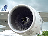 thin round intake lip with internal compression due to space constrains of the nacelle


Supersonic inlets
Supersonic intakes exploit shock waves to decelerate the airflow to a subsonic condition at compressor entry.
There are basically two forms of shock waves:
1) Normal shock waves lie perpendicular to the direction of the flow. These form sharp fronts and shock the flow to subsonic speeds. Microscopically the air molecules smash into the subsonic crowd of molecules like alpha rays. Normal shock waves tend to cause a large drop in stagnation pressure. Basically, the higher the supersonic entry Mach number to a normal shock wave, the lower the subsonic exit Mach number and the stronger the shock (i.e. the greater the loss in stagnation pressure across the shock wave).
2) Conical (3-dimensional) and oblique shock waves (2D)[51] are angled rearwards, like the bow wave on a ship or boat, and radiate from a flow disturbance such as a cone or a ramp. For a given inlet Mach number, they are weaker than the equivalent normal shock wave and, although the flow slows down, it remains supersonic throughout. Conical and oblique shock waves turn the flow, which continues in the new direction, until another flow disturbance is encountered downstream.
A sharp-lipped version of the pitot intake, described above for subsonic applications, performs quite well at moderate supersonic flight speeds. A detached normal shock wave forms just ahead of the intake lip and 'shocks' the flow down to a subsonic velocity. However, as flight speed increases, the shock wave becomes stronger, causing a larger percentage decrease in stagnation pressure (i.e. poorer pressure recovery). An early US supersonic fighter, the F-100 Super Sabre, used such an intake.

More advanced supersonic intakes, excluding pitots:
a) exploit a combination of conical shock wave/s and a normal shock wave to improve pressure recovery at high supersonic flight speeds. Conical shock wave/s are used to reduce the supersonic Mach number at entry to the normal shock wave, thereby reducing the resultant overall shock losses.
b) have a design shock-on-lip flight Mach number, where the conical/oblique shock wave/s intercept the cowl lip, thus enabling the streamtube capture area to equal the intake lip area. However, below the shock-on-lip flight Mach number, the shock wave angle/s are less oblique, causing the streamline approaching the lip to be deflected by the presence of the cone/ramp. Consequently, the intake capture area is less than the intake lip area, which reduces the intake airflow. Depending on the airflow characteristics of the engine, it may be desirable to lower the ramp angle or move the cone rearwards to refocus the shockwaves onto the cowl lip to maximise intake airflow.
c) are designed to have a normal shock in the ducting downstream of intake lip, so that the flow at compressor/fan entry is always subsonic. However, if the engine is throttled back, there is a reduction in the corrected airflow of the LP compressor/fan, but (at supersonic conditions) the corrected airflow at the intake lip remains constant, because it is determined by the flight Mach number and intake incidence/yaw. This discontinuity is overcome by the normal shock moving to a lower cross-sectional area in the ducting, to decrease the Mach number at entry to the shockwave. This weakens the shockwave, improving the overall intake pressure recovery. So, the absolute airflow stays constant, whilst the corrected airflow at compressor entry falls (because of a higher entry pressure). Excess intake airflow may also be dumped overboard or into the exhaust system, to prevent the conical/oblique shock waves being disturbed by the normal shock being forced too far forward by engine throttling.
Many second generation supersonic fighter aircraft featured an inlet cone, which was used to form the conical shock wave. This type of inlet cone is clearly seen at the very front of the English Electric Lightning and MiG-21 aircraft, for example.
The same approach can be used for air intakes mounted at the side of the fuselage, where a half cone serves the same purpose with a semicircular air intake, as seen on the F-104 Starfighter and BAC TSR-2.
Some intakes are biconic; that is they feature two conical surfaces: the first cone is supplemented by a second, less oblique, conical surface, which generates an extra conical shockwave, radiating from the junction between the two cones. A biconic intake is usually more efficient than the equivalent conical intake, because the entry Mach number to the normal shock is reduced by the presence of the second conical shock wave.
A very sophisticated conical intake was featured on the SR-71's Pratt & Whitney J58s that could move a conical spike fore and aft within the engine nacelle, preventing the shockwave formed on the spike from entering the engine and stalling the engine, while keeping it close enough to give good compression. Movable cones are uncommon.
A more sophisticated design than cones is to angle the intake so that one of its edges forms a ramp. An oblique shockwave will form at the start of the ramp. The Century Series of US jets featured several variants of this approach, usually with the ramp at the outer vertical edge of the intake, which was then angled back inward towards the fuselage. Typical examples include the Republic F-105 Thunderchief and F-4 Phantom.

Later this evolved so that the ramp was at the top horizontal edge rather than the outer vertical edge, with a pronounced angle downwards and rearwards. This design simplified the construction of intakes and allowed use of variable ramps to control airflow into the engine. Most designs since the early 1960s now feature this style of intake, for example the F-14 Tomcat, Panavia Tornado and Concorde.
From another point of view, like in a supersonic nozzle the corrected (or non-dimensional) flow has to be the same at the intake lip, at the intake throat and at the turbine. One of this three can be fixed. For inlets the throat is made variable and some air is bypassed around the turbine and directly fed into the afterburner. Unlike in a nozzle the inlet is either unstable or inefficient, because a normal shock wave in the throat will suddenly move to the lip, thereby increasing the pressure at the lip, leading to drag and reducing the pressure recovery, leading to turbine surge and the loss of one SR-71.
Compressors


Axial compressors rely on spinning blades that have aerofoil sections, similar to aeroplane wings. As with aeroplane wings in some conditions the blades can stall. If this happens, the airflow around the stalled compressor can reverse direction violently. Each design of a compressor has an associated operating map of airflow versus rotational speed for characteristics peculiar to that type (see compressor map).
At a given throttle condition, the compressor operates somewhere along the steady state running line. Unfortunately, this operating line is displaced during transients. Many compressors are fitted with anti-stall systems in the form of bleed bands or variable geometry stators to decrease the likelihood of surge. Another method is to split the compressor into two or more units, operating on separate concentric shafts.
Another design consideration is the average stage loading. This can be kept at a sensible level either by increasing the number of compression stages (more weight/cost) or the mean blade speed (more blade/disc stress).
Although large flow compressors are usually all-axial, the rear stages on smaller units are too small to be robust. Consequently, these stages are often replaced by a single centrifugal unit. Very small flow compressors often employ two centrifugal compressors, connected in series. Although in isolation centrifugal compressors are capable of running at quite high pressure ratios (e.g. 10:1), impeller stress considerations limit the pressure ratio that can be employed in high overall pressure ratio engine cycles.
Increasing overall pressure ratio implies raising the high pressure compressor exit temperature. This implies a higher high pressure shaft speed, to maintain the datum blade tip Mach number on the rear compressor stage. Stress considerations, however, may limit the shaft speed increase, causing the original compressor to throttle-back aerodynamically to a lower pressure ratio than datum.
Combustors

Flame fronts generally travel at just Mach 0.05, whereas airflows through jet engines are considerably faster than this. Combustors typically employ structures to give a sheltered combustion zone called a flame holder. Combustor configurations include can, annular, and can-annular.
Great care must be taken to keep the flame burning in a moderately fast moving airstream, at all throttle conditions, as efficiently as possible. Since the turbine cannot withstand stoichiometric temperatures (a mixture ratio of around 15:1), some of the compressor air is used to quench the exit temperature of the combustor to an acceptable level (an overall mixture ratio of between 45:1 and 130:1 is used[52]). Air used for combustion is considered to be primary airflow, while excess air used for cooling is called secondary airflow. The secondary airflow is ported through many small holes in the burner cans to create an blanket of cooler air to insulate the metal surfaces of the combustion can from the flame. If the metal were subjected to the direct flame for any length of time, it would eventually burn through.
Rocket engines, being a non 'duct engine' have quite different combustor systems, and the mixture ratio is usually much closer to being stochiometric in the main chamber. These engines generally lack flame holders and combustion occurs at much higher temperatures, there being no turbine downstream. However, liquid rocket engines frequently employ separate burners to power turbopumps, and these burners usually run far off stochiometric so as to lower turbine temperatures in the pump.
Turbines

Because a turbine expands from high to low pressure, there is no such thing as turbine surge or stall. The turbine needs fewer stages than the compressor, mainly because the higher inlet temperature reduces the deltaT/T (and thereby the pressure ratio) of the expansion process. The blades have more curvature and the gas stream velocities are higher.
Designers must, however, prevent the turbine blades and vanes from melting in a very high temperature and stress environment. Consequently bleed air extracted from the compression system is often used to cool the turbine blades/vanes internally. Other solutions are improved materials and/or special insulating coatings. The discs must be specially shaped to withstand the huge stresses imposed by the rotating blades. They take the form of impulse, reaction, or combination impulse-reaction shapes. Improved materials help to keep disc weight down.
Afterburners (reheat)

Due to temperature limitations with the gas turbines, jet engines do not consume all the oxygen in the air ('run stoichiometric'). Afterburners burn the remaining oxygen after exiting the turbines, but usually do so inefficiently due to the low pressures typically found at this part of the jet engine make the subsequent nozzle inefficient at extracting the heat energy; however afterburners still gain significant thrust, which can be useful. Engines intended for extended use with afterburners often have variable nozzles and other details.
Nozzles

The primary objective of a nozzle is to use the heat and pressure of the exhaust gas to accelerate the jet to high speed so as to efficiently propel the vehicle. For air-breathing engines, if the fully expanded jet has a higher speed than the aircraft's airspeed, then there is a net rearward momentum gain to the air and there will be a forward thrust on the airframe.
Simple convergent nozzles are used on many jet engines. This forms a restricted opening which raises the pressure in the rest of the engine and increases the speed of the jet. However, if the nozzle pressure ratio is above the critical value (about 1.8:1) a convergent nozzle will 'choke', resulting in the jet being emitted at the speed of sound, higher pressure differences then gives much lower improvement in performance- although much of the gross thrust produced will still be from the jet momentum, some additional (pressure) thrust will come from the imbalance between the throat static pressure and atmospheric pressure.
Many military combat engines incorporate an afterburner (or reheat) in the engine exhaust system. When the system is lit, the nozzle throat area must be increased, to accommodate the extra exhaust volume flow, so that the turbomachinery is unaware that the afterburner is lit. A variable throat area is achieved by moving a series of overlapping petals, which approximate the circular nozzle cross-section.
At high nozzle pressure ratios, the exit pressure is often above ambient and much of the expansion will take place downstream of a convergent nozzle, which is inefficient. Consequently, some jet engines (notably rockets) incorporate a convergent-divergent nozzle, to allow most of the expansion to take place against the inside of a nozzle to maximise thrust. However, unlike the fixed con-di nozzle used on a conventional rocket motor, when such a device is used on a turbojet engine it has to be a complex variable geometry device, to cope with the wide variation in nozzle pressure ratio encountered in flight and engine throttling. This further increases the weight and cost of such an installation.

The simpler of the two is the ejector nozzle, which creates an effective nozzle through a secondary airflow and spring-loaded petals. At subsonic speeds, the airflow constricts the exhaust to a convergent shape. As the aircraft speeds up, the two nozzles dilate, which allows the exhaust to form a convergent-divergent shape, speeding the exhaust gasses past Mach 1. More complex engines can actually use a tertiary airflow to reduce exit area at very low speeds. Advantages of the ejector nozzle are relative simplicity and reliability. Disadvantages are average performance (compared to the other nozzle type) and relatively high drag due to the secondary airflow. Notable aircraft to have utilized this type of nozzle include the SR-71, Concorde, F-111, and Saab Viggen
For higher performance, it is necessary to use an iris nozzle. This type uses overlapping, hydraulically adjustable "petals". Although more complex than the ejector nozzle, it has significantly higher performance and smoother airflow. As such, it is employed primarily on high-performance fighters such as the F-14, F-15, F-16, though is also used in high-speed bombers such as the B-1B. Some modern iris nozzles additionally have the ability to change the angle of the thrust (see thrust vectoring).

Rocket motors also employ convergent-divergent nozzles, but these are usually of fixed geometry, to minimize weight. Because of the much higher nozzle pressure ratios experienced, rocket motor con-di nozzles have a much greater area ratio (exit/throat) than those fitted to jet engines. The Convair F-106 Delta Dart has used such a nozzle design, as part of its overall design specification as a aerospace interceptor for high-altitude bomber interception, where conventional nozzle design would prove ineffective.
At the other extreme, some high bypass ratio civil turbofans use an extremely low area ratio (less than 1.01 area ratio), convergent-divergent, nozzle on the bypass (or mixed exhaust) stream, to control the fan working line. The nozzle acts as if it has variable geometry. At low flight speeds the nozzle is unchoked (less than a Mach number of unity), so the exhaust gas speeds up as it approaches the throat and then slows down slightly as it reaches the divergent section. Consequently, the nozzle exit area controls the fan match and, being larger than the throat, pulls the fan working line slightly away from surge. At higher flight speeds, the ram rise in the intake increases nozzle pressure ratio to the point where the throat becomes choked (M=1.0). Under these circumstances, the throat area dictates the fan match and being smaller than the exit pushes the fan working line slightly towards surge. This is not a problem, since fan surge margin is much better at high flight speeds.
Thrust reversers
These either consist of cups that swing across the end of the exhaust nozzle and deflect the jet thrust forwards (as in the DC-9), or they are two panels behind the cowling that slide backward and reverse only the fan thrust (the fan produces the majority of the thrust). Fan air redirection is performed by devices called "blocker doors" and "cascade vanes". This is the case on many large aircraft such as the 747, C-17, KC-10, etc. If you are on an aircraft and you hear the engines increasing in power after landing, it is usually because the thrust reversers are deployed. The engines are not actually spinning in reverse, as the term may lead you to believe. The reversers are used to slow the aircraft more quickly and reduce wear on the wheel brakes.
Cooling systems
All jet engines require high temperature gas for good efficiency, typically achieved by combusting hydrocarbon or hydrogen fuel. Combustion temperatures can be as high as 3500K (5841F) in rockets, far above the melting point of most materials, but normal airbreathing jet engines use rather lower temperatures.
Cooling systems are employed to keep the temperature of the solid parts below the failure temperature.
Air systems
A complex around combustor and is injected into the rim of the rotating turbine disc. The cooling air then passes through complex passages within the turbine blades. After removing heat from the blade material, the air (now fairly hot) is vented, via cooling holes, into the main gas stream. Cooling air for the turbine vanes undergoes a similar process.
Cooling the leading edge of the blade can be difficult, because the pressure of the cooling air just inside the cooling hole may not be much different from that of the oncoming gas stream. One solution is to incorporate a cover plate on the disc. This acts as a centrifugal compressor to pressurize the cooling air before it enters the blade. Another solution is to use an ultra-efficient turbine rim seal to pressurize the area where the cooling air passes across to the rotating disc.
Seals are used to prevent oil leakage, control air for cooling and prevent stray air flows into turbine cavities.
A series of (e.g. labyrinth) seals allow a small flow of bleed air to wash the turbine disc to extract heat and, at the same time, pressurize the turbine rim seal, to prevent hot gases entering the inner part of the engine. Other types of seals are hydraulic, brush, carbon etc.
Small quantities of compressor bleed air are also used to cool the shaft, turbine shrouds, etc. Some air is also used to keep the temperature of the combustion chamber walls below critical. This is done using primary and secondary airholes which allow a thin layer of air to cover the inner walls of the chamber preventing excessive heating.
Exit temperature is dependent on the turbine upper temperature limit depending on the material. Reducing the temperature will also prevent thermal fatigue and hence failure. Accessories may also need their own cooling systems using air from the compressor or outside air.
Air from compressor stages is also used for heating of the fan, airframe anti-icing and for cabin heat. Which stage is bled from depends on the atmospheric conditions at that altitude.
Fuel system
Apart from providing fuel to the engine, the fuel system is also used to control propeller speeds, compressor airflow and cool lubrication oil. Fuel is usually introduced by an atomized spray, the amount of which is controlled automatically depending on the rate of airflow.
So the sequence of events for increasing thrust is, the throttle opens and fuel spray pressure is increased, increasing the amount of fuel being burned. This means that exhaust gases are hotter and so are ejected at higher acceleration, which means they exert higher forces and therefore increase the engine thrust directly. It also increases the energy extracted by the turbine which drives the compressor even faster and so there is an increase in air flowing into the engine as well.
Obviously, it is the rate of the mass of the airflow that matters since it is the change in momentum (mass x velocity) that produces the force. However, density varies with altitude and hence inflow of mass will also vary with altitude, temperature etc. which means that throttle values will vary according to all these parameters without changing them manually.
This is why fuel flow is controlled automatically. Usually there are 2 systems, one to control the pressure and the other to control the flow. The inputs are usually from pressure and temperature probes from the intake and at various points through the engine. Also throttle inputs, engine speed etc. are required. These affect the high pressure fuel pump.
Fuel control unit (FCU)
This element is something like a mechanical computer. It determines the output of the fuel pump by a system of valves which can change the pressure used to cause the pump stroke, thereby varying the amount of flow.
Take the possibility of increased altitude where there will be reduced air intake pressure. In this case, the chamber within the FCU will expand which causes the spill valve to bleed more fuel. This causes the pump to deliver less fuel until the opposing chamber pressure is equivalent to the air pressure and the spill valve goes back to its position.
When the throttle is opened, it releases i.e. lessens the pressure which lets the throttle valve fall. The pressure is transmitted (because of a back-pressure valve i.e. no air gaps in fuel flow) which closes the FCU spill valves (as they are commonly called) which then increases the pressure and causes a higher flow rate.
The engine speed governor is used to prevent the engine from over-speeding. It has the capability of disregarding the FCU control. It does this by use of a diaphragm which senses the engine speed in terms of the centrifugal pressure caused by the rotating rotor of the pump. At a critical value, this diaphragm causes another spill valve to open and bleed away the fuel flow.
There are other ways of controlling fuel flow for example with the dash-pot throttle lever. The throttle has a gear which meshes with the control valve (like a rack and pinion) causing it to slide along a cylinder which has ports at various positions. Moving the throttle and hence sliding the valve along the cylinder, opens and closes these ports as designed. There are actually 2 valves viz. the throttle and the control valve. The control valve is used to control pressure on one side of the throttle valve such that it gives the right opposition to the throttle control pressure. It does this by controlling the fuel outlet from within the cylinder.
So for example, if the throttle valve is moved up to let more fuel in, it will mean that the throttle valve has moved into a position which allows more fuel to flow through and on the other side, the required pressure ports are opened to keep the pressure balance so that the throttle lever stays where it is.
At initial acceleration, more fuel is required and the unit is adapted to allow more fuel to flow by opening other ports at a particular throttle position. Changes in pressure of outside air i.e. altitude, speed of aircraft etc are sensed by an air capsule.
Propellant pump
Propellant pumps are usually present to raise the propellant pressure above the pressure in the combustion chamber so that the fuel can be injected. Fuel pumps are usually driven by the main shaft, via gearing.
Turbopumps
Turbopumps are centrifugal pumps which are spun by gas turbines and are used to raise the propellant pressure above the pressure in the combustion chamber so that it can be injected and burnt. Turbopumps are very commonly used with rockets, but ramjets and turbojets also have been known to use them. The drive gases for the turbopump is usually generated in separate chambers with off-stochiometric combustion and the relatively small mass flow is dumped either through a special nozzle, or at a point in the main nozzle; both cause a small reduction in performance. In some cases (notably the Space Shuttle Main Engine) staged combustion is used, and the pump gas exhaust is returned into the main chamber where the combustion is completed and essentially no loss of performance due to pumping losses then occurs.
Ramjet turbopumps use ram air expanding through a turbine.
Engine starting system
The fuel system as explained above is one of the two systems required for starting the engine. The other is the actual ignition of the air/fuel mixture in the chamber. Usually, an auxiliary power unit is used to start the engines. It has a starter motor which has a high torque transmitted to the compressor unit. When the optimum speed is reached, i.e. the flow of gas through the turbine is sufficient, the turbines take over.
There are a number of different starting methods such as electric, hydraulic, pneumatic etc.
The electric starter works with gears and clutch plate linking the motor and the engine. The clutch is used to disengage when optimum speed is achieved. This is usually done automatically. The electric supply is used to start the motor as well as for ignition. The voltage is usually built up slowly as starter gains speed.
Some military aircraft need to be started quicker than the electric method permits and hence they use other methods such as a cartridge turbine starter or "cart starter". This is an impulse turbine impacted by burning gases from a cartridge, usually created by igniting a solid propellant similar to gun powder. It is geared to rotate the engine and also connected to an automatic disconnect system, or overrunning clutch. The cartridge is set alight electrically and used to turn the starter's turbine.
Another turbine starter system is almost exactly like a little engine. Again the turbine is connected to the engine via gears. However, the turbine is turned by burning gases - usually the fuel is isopropyl nitrate (or sometimes Hydrazine) stored in a tank and sprayed into a combustion chamber. Again, it is ignited with a spark plug. Everything is electrically controlled, such as speed etc.
Most Commercial aircraft and large Military Transport airplanes usually use what is called an auxiliary power unit or APU. It is normally a small gas turbine. Thus, one could say that using such an APU is using a small gas turbine to start a larger one. Low pressure (40-70 psi), high volume air from the compressor section of the APU is bled off through a system of pipes to the engines where it is directed into the starting system. This "bleed air" is directed into a mechanism to start the engine turning and begin pulling in air. The starter is usually an "air turbine" type, similar to the cartridge starter, but uses APU's bleed air instead of the burning gases of the propellant cartridge. Most cart starters can also use APU air to turn them. When the rotating speed of the engine is sufficient to pull in enough air to support combustion, fuel is introduced and ignited. Once the engine ignites and reaches idle speed, the bleed air and ignition systems are shut off.
The APUs on aircraft such as the Boeing 737 and Airbus A320 can be seen at the extreme rear of the aircraft. This is the typical location for an APU on most commercial airliners although some may be within the wing root (Boeing 727) or the aft fuselage (DC-9/MD80) as examples and some military transports carry their APU's in one of the main landing gear pods (C-141).
Some APUs are mounted on wheeled carts, so they can be towed and used on different aircraft. They are connected by a hose to the aircraft ducting, which includes a check valve to allow the APU air to flow into the aircraft, while not allowing the main engine's bleed air to exit through the duct.
The APUs also provide enough power to keep the cabin lights, pressure and other systems on while the engines are off. The valves used to control the airflow are usually electrically controlled. They automatically close at a pre-determined speed. As part of the starting sequence on some engines fuel is combined with the supplied air and burned instead of using just air. This usually produces more power per unit weight.
Usually an APU is started by its own electric starter motor which is switched off at the proper speed automatically. When the main engine starts up and reaches the right conditions, this auxiliary unit is then switched off and disengages slowly.
Hydraulic pumps can also be used to start some engines through gears. The pumps are electrically controlled on the ground.
A variation of this is the APU installed in a Boeing F/A-18 Hornet; it is started by a hydraulic motor, which itself receives energy stored in an accumulator. This accumulator is recharged after the right engine is started and develops hydraulic pressure, or by a hand pump in the right hand main landing gear well.
Ignition
Usually there are two ignitor plugs in different positions in the combustion system. A high voltage spark is used to ignite the gases. The voltage is stored up from a low voltage (usually 28 vDC) supply provided by the aircraft batteries. It builds up to the right value in the ignition "exciters" (similar to automobile ignition coils) and is then released as a high energy spark. Depending on various conditions, such as flying through heavy rainfall, the igniter continues to provide sparks to prevent combustion from failing if the flame inside goes out. Of course, in the event that the flame does go out, there must be provision to relight. There is a limit of altitude and air speed at which an engine can obtain a satisfactory relight.
For example, the General Electric F404-400 uses one ignitor for the combustor and one for the afterburner; the ignition system for the A/B incorporates an ultraviolet flame sensor to activate the ignitor.
It should be noted that most modern ignition systems provide enough energy (20-40,000 volts) to be a lethal hazard should a person be in contact with the electrical lead when the system is activated, so team communication is vital when working on these systems.
Lubrication system
A lubrication system serves to ensure lubrication of the bearings and gears and to maintain sufficiently cool temperatures, mostly by eliminating friction. The lubricant can also be utilized to cool other parts such as walls and other structural members directly via targeted oil flows. The lubrication system also transports wear particles from the insides of the engine and flushes them through a filter to keep the oil and oil wetted components clean.
The lubricant is isolated from the external parts of the engine through various sealing mechanisms, which also prevent dirt and other foreign objects from contaminating the oil and from reaching the bearings, gears, and other moving parts, and typically flows in a loop (is not intentionally consumed through engine usage). The lubricant must be able to flow easily at relatively low temperatures and not disintegrate or break down at very high temperatures.
Usually the lubrication system has subsystems that deal individually with the lubrication supply system of an engine, scavenging (oil return system), and a breather (venting excess air from internal compartments).
The pressure system components are typically include an oil tank and de-aerator, main oil pump, main oil filter/filter bypass valve, pressure regulating valve (PRV), oil cooler/by pass valve and tubing/jets.
Usually the flow is from the tank to the pump inlet and PRV, pumped to main oil filter or its bypass valve and oil cooler, then through some more filters to jets in the bearings.
Using the PRV method of control, means that the pressure of the feed oil must be below a critical value (usually controlled by other valves which can leak out excess oil back to tank if it exceeds the critical value). The valve opens at a certain pressure and oil is kept moving at a constant rate into the bearing chamber.
If the engine power setting increases, the pressure within the bearing chamber also typically increases, which means the pressure difference between the lubricant feed and the chamber reduces which could reduce slow rate of oil when it is needed even more. As a result, some PRVs can adjust their spring force values using this pressure change in the bearing chamber proportionally to keep the lubricant flow constant.
Control system
Most jet engines are controlled digitally using Full Authority Digital Electronics Control systems, however some systems use mechanical devices.
Advanced designs
J-58 combined ramjet/turbojet
The SR-71 Blackbird's Pratt & Whitney J58 engines were rather unusual. They could convert in flight from being largely a turbojet to being largely a compressor-assisted ramjet. At high speeds (above Mach 2.4), the engine used variable geometry vanes to direct excess air through 6 bypass pipes from downstream of the fourth compressor stage into the afterburner.[53] 80% of the SR-71's thrust at high speed was generated in this way, giving much higher thrust, improving specific impulse by 10-15%, and permitting continuous operation at Mach 3.2. The name coined for this setup is turbo-ramjet.
Hydrogen fuelled air-breathing jet engines
Jet engines can be run on almost any fuel. Hydrogen is a highly desirable fuel, as, although the energy per mole is not unusually high, the molecule is very much lighter than other molecules. It turns out that the energy per kg of hydrogen is twice that of more common fuels and this gives twice the specific impulse. In addition jet engines running on hydrogen are quite easy to build- the first ever turbojet was run on hydrogen. Also, although not duct engines, hydrogen fuelled rocket engines have seen extensive use.
However, in almost every other way, hydrogen is problematic. The downside of hydrogen is its density, in gaseous form the tanks are impractical for flight, but even in the form of liquid hydrogen it has a density one fourteenth that of water. It is also deeply cryogenic and requires very significant insulation that precludes it being stored in wings. The overall vehicle ends up very large, and they would be difficult for most airports to accommodate. Finally, pure hydrogen is not found in nature, and must be manufactured either via steam reforming or expensive electrolysis. Nevertheless, research is ongoing and hydrogen fuelled aircraft designs do exist that may be feasible.
Precooled jet engines
An idea originated by Robert P. Carmichael in 1955 [54] is that hydrogen fuelled engines could theoretically have much higher performance than hydrocarbon fuelled engines if a heat exchanger were used to cool the incoming air. The low temperature allows lighter materials to be used, a higher mass-flow through the engines, and permits combustors to inject more fuel without overheating the engine.
This idea leads to plausible designs like SABRE, that might permit single-stage-to-orbit,[55] and ATREX, that might permit jet engines to be used up to hypersonic speeds and high altitudes for boosters for launch vehicles. The idea is also being researched by the EU for a concept to achieve non-stop antipodal supersonic passenger travel at Mach 5 (Reaction Engines A2).
Nuclear-powered ramjet
Project Pluto was a nuclear-powered ramjet, intended for use in a cruise missile. Rather than combusting fuel as in regular jet engines, air was heated using a high-temperature, unshielded nuclear reactor. This dramatically increased the engine burn time, and the ramjet was predicted to be able to cover any required distance at supersonic speeds (Mach 3 at tree-top height).
However, there was no obvious way to stop it once it had taken off, which would be a great disadvantage in any non-disposable application. Also, because the reactor was unshielded, it was dangerous to be in or around the flight path of the vehicle (although the exhaust itself wasn't radioactive). These disadvantages limit the application to warhead delivery system for all-out nuclear war, which it was being designed for.
Scramjets
Scramjets are an evolution of ramjets that are able to operate at much higher speeds than any other kind of airbreathing engine. They share a similar structure with ramjets, being a specially-shaped tube that compresses air with no moving parts through ram-air compression. Scramjets, however, operate with supersonic airflow through the entire engine. Thus, scramjets do not have the diffuser required by ramjets to slow the incoming airflow to subsonic speeds.
Scramjets start working at speeds of at least Mach 4, and have a maximum useful speed of approximately Mach 17.[56] Due to aerodynamic heating at these high speeds, cooling poses a challenge to engineers.
Environmental considerations
Jet engines are usually run on fossil fuel propellant, and in that case, are a net source of carbon to the atmosphere.
Some scientists believe that jet engines are also a source of global dimming due to the water vapour in the exhaust causing cloud formations.
Nitrogen compounds are also formed from the combustion process from atmospheric nitrogen. At low altitudes this is not thought to be especially harmful, but for supersonic aircraft that fly in the stratosphere some destruction of ozone may occur.
Sulphates are also emitted if the fuel contains sulphur.
Safety and reliability
Jet engines are usually very reliable and have a very good safety record. However failures do sometimes occur.
Compressor blade containment
The most likely failure is compressor blade failure, and modern jet engines are designed with structures that can catch these blades and keep them contained within the engine casing. Verification of a jet engine design involves testing that this system works correctly.
Bird strike
Bird strike is an aviation term for a collision between a bird and an aircraft. It is a common threat to aircraft safety and has caused a number of fatal accidents. In 1988 an Ethiopian Airlines Boeing 737 sucked pigeons into both engines during take-off and then crashed in an attempt to return to the Bahir Dar airport; of the 104 people aboard, 35 died and 21 were injured. In another incident in 1995, a Dassault Falcon 20 crashed at a Paris airport during an emergency landing attempt after sucking lapwings into an engine, which caused an engine failure and a fire in the airplane fuselage; all 10 people on board were killed.[57]
Modern jet engines have the capability of surviving an ingestion of a bird. Small fast planes, such as military jet fighters, are at higher risk than big heavy multi-engine ones. This is due to the fact that the fan of a high-bypass turbofan engine, typical on transport aircraft, acts as a centrifugal separator to force ingested materials (birds, ice, etc.) to the outside of the fan's disc. As a result, such materials go through the relatively unobstructed bypass duct, rather than through the core of the engine, which contains the smaller and more delicate compressor blades. Military aircraft designed for high-speed flight typically have pure turbojet, or low-bypass turbofan engines, increasing the risk that ingested materials will get into the core of the engine to cause damage.
The highest risk of the bird strike is during the takeoff and landing, in low altitudes, which is in the vicinity of the airports.
Uncontained failures
One class of failures that has caused accidents in particular is uncontained failures, where rotary parts of the engine break off and exit through the case. These can cut fuel or control lines, and can penetrate the cabin. Although fuel and control lines are usually duplicated for reliability the United Airlines Flight 232 crash was caused when all control lines were simultaneously severed. This was caused by a 'disc failure' where the relatively heavy structural parts of the high speed turbine rotor fractured. The discs are intended to never fail in this way, but manufacturing defects have nevertheless occasionally permitted this to occur.
References
- ^ Encyclopedia Britannica: Internal Combustion Engine
- ^ How many air-miles are left in the world’s fuel tank?
- ^ U.S. Airlines: Operating in an Era of High Jet Fuel Prices
- ^ propeller efficiency
- ^ Patent number 554,906
- ^ Gyorgy, Nagy Istvan, “Albert Fono: A Pioneer of Jet Propulsion”, International Astronautical Congress, 1977, IAF/IAA
- ^ Dugger, Gordon L. (1969). Ramjets. American Institute of Aeronautics and Astronautics, p. 15.
- ^ Maxime Guillaume,"Propulseur par réaction sur l'air," French patent no. 534,801 (filed: 3 May 1921; issued: 13 January 1922). Available on-line (in French) at: http://v3.espacenet.com/origdoc?DB=EPODOC&IDX=FR534801&F=0&QPN=FR534801 .
- ^ sod1280.tmp
- ^ PBS - Chasing the Sun - Frank Whittle
- ^ BBC - History - Frank Whittle (1907 - 1996)
- ^ Frank Whittle, "Improvements relating to the propulsion of aircraft and other vehicles," British patent no. 347,206 (filed: 16 January 1930). Available on-line at: http://v3.espacenet.com/origdoc?DB=EPODOC&IDX=GB347206&F=0&QPN=GB347206 .
- ^ The History of the Jet Engine - Sir Frank Whittle - Hans Von OhainOhain said that he had not read Whittle's patent and Whittle believed him (Frank Whittle 1907-1996) however the Whittle patent was in German libraries and Whittle's son had suspicions that Ohain had read or heard of it (The History of the Jet Engine - Sir Frank Whittle a genius betrayed - )
- ^ ch10-3
- ^ [1]
- ^ a b [2]
- ^ [3]
- ^ [4]
- ^ Merging Air and Space
- ^ In Newtonian mechanics kinetic energy is frame dependent. The speed must be measured in the center of mass frame of the vehicle and less obviously it's reaction mass, which it is typically in at take-off.
- ^ K.Honicke, R.Lindner, P.Anders, M.Krahl, H.Hadrich, K.Rohricht. Beschreibung der Konstruktion der Triebwerksanlagen. Interflug, Berlin, 1968
- ^ Rocket Propulsion elements- seventh edition, pg 37-38
- ^ "NK33". Encyclopedia Astronautica.
- ^ "SSME". Encyclopedia Astronautica.
- ^ a b c d e f g h i j k l m n o p q r s t u v w x y z aa ab ac ad ae af ag Nathan Meier (21 Mar 2005). "Military Turbojet/Turbofan Specifications". Archived from the original on 11 February 2021.
- ^ a b "Flanker". AIR International Magazine. 23 March 2017.
- ^ a b "EJ200 turbofan engine" (PDF). MTU Aero Engines. April 2016.
- ^ a b c d e f g h i j k Kottas, Angelos T.; Bozoudis, Michail N.; Madas, Michael A. "Turbofan Aero-Engine Efficiency Evaluation: An Integrated Approach Using VSBM Two-Stage Network DEA" (PDF). doi:10.1016/j.omega.2019.102167.
- ^ a b c Élodie Roux (2007). "Turbofan and Turbojet Engines: Database Handbook" (PDF). p. 126. ISBN 9782952938013.
- ^ a b c d e f g h i j k Nathan Meier (3 Apr 2005). "Civil Turbojet/Turbofan Specifications". Archived from the original on 17 August 2021.
- ^ a b Ilan Kroo. "Data on Large Turbofan Engines". Aircraft Design: Synthesis and Analysis. Stanford University. Archived from the original on 11 January 2017.
- ^ a b c David Kalwar (2015). "Integration of turbofan engines into the preliminary design of a high-capacity short-and medium-haul passenger aircraft and fuel efficiency analysis with a further developed parametric aircraft design software" (PDF).
- ^ "Purdue School of Aeronautics and Astronautics Propulsion Web Page - TFE731".
- ^ a b Lloyd R. Jenkinson & al. (30 Jul 1999). "Civil Jet Aircraft Design: Engine Data File". Elsevier/Butterworth-Heinemann.
- ^ a b c d "Gas Turbine Engines" (PDF). Aviation Week. 28 January 2008. pp. 137–138.
- ^ Élodie Roux (2007). "Turbofan and Turbojet Engines: Database Handbook". ISBN 9782952938013.
- ^ a b Vladimir Karnozov (August 19, 2019). "Aviadvigatel Mulls Higher-thrust PD-14s To Replace PS-90A". AIN Online.
- ^ Wade, Mark. "RD-0410". Encyclopedia Astronautica. Retrieved 2009-09-25.
- ^ РД0410. Ядерный ракетный двигатель. Перспективные космические аппараты [RD0410. Nuclear Rocket Engine. Advanced launch vehicles]. KBKhA - Chemical Automatics Design Bureau. Archived from the original on 30 November 2010.
- ^ "Aircraft: Lockheed SR-71A Blackbird". Archived from the original on 2012-07-29. Retrieved 2010-04-16.
- ^ "Factsheets : Pratt & Whitney J58 Turbojet". National Museum of the United States Air Force. Archived from the original on 2015-04-04. Retrieved 2010-04-15.
- ^ "Rolls-Royce SNECMA Olympus - Jane's Transport News". Archived from the original on 2010-08-06. Retrieved 2009-09-25.
With afterburner, reverser and nozzle ... 3,175 kg ... Afterburner ... 169.2 kN
- ^ Military Jet Engine Acquisition, RAND, 2002.
- ^ "Конструкторское бюро химавтоматики" - Научно-исследовательский комплекс / РД0750. [«Konstruktorskoe Buro Khimavtomatiky» - Scientific-Research Complex / RD0750.]. KBKhA - Chemical Automatics Design Bureau. Archived from the original on 26 July 2011.
- ^ Wade, Mark. "RD-0146". Encyclopedia Astronautica. Retrieved 2009-09-25.
- ^ SSME
- ^ "RD-180". Retrieved 2009-09-25.
- ^ Encyclopedia Astronautica: F-1
- ^ Astronautix NK-33 entry
- ^ High Speed Propulsion
- ^ Note: Comments made regarding 3 dimensional conical shock waves, generally also apply to 2D oblique shock waves.
- ^ The Combustion Chamber
- ^ J58
- ^ NASA history Other Interests in Hydrogen
- ^ The Skylon Spaceplane
- ^ Astronautix X30
- ^ Transport Canada - Sharing the Skies
- John Golley (1997). Genesis of the Jet: Frank Whittle and the Invention of the Jet Engine. Crowood Press. ISBN 1-85310-860-X.
- David S Brooks (1997). Vikings at Waterloo: Wartime Work on the Whittle Jet Engine by the Rover Company. Rolls-Royce Heritage Trust. ISBN 1-872922-08-2
See also
- Jet engine performance
- Jet aircraft
- Jetboat
- Turbofan
- Variable Cycle Engine
- Turbojet
- Turboprop
- Turboshaft
- Propfan
- Pulse jet
- Turborocket
- Ramjet
- Rocket engine nozzles
- Spacecraft propulsion
- Supercharger
- Turbocharger
- Afterburner
- Water injection (engines)
- Thrust reversal
- Gas turbine
- Kurt Schreckling who built practical jet engines for model aircraft
- Wikibooks: Jet propulsion
External links
- A New “Open Rotor” Jet Engine That Could Reduce Fuel Consumption
- Technology Speed of Civil Jet Engines
- Animated Jet Engines to understand how it works
- RMCybernetics - A simple Homemade Jet Engine
- Journey through a jet engine(flash)
- How Stuff Works article on how a Gas Turbine Engine works
- Influence of the Jet Engine on the Aerospace Industry
- An Overview of Military Jet Engine History (Rand Corp., 24 pgs, PDF)
- A jet propulsion bicycle
- Basic jet engine tutorial (Quicktime Video
- Jet powered model of an Airbus A330 at 1/16 scale
- Pulsejet in aeromodelling
- Interactive jet engine simulator for learning
Template:Link FA
Template:Link FA
Template:Link FA
Cite error: There are <ref group=lower-alpha> tags or {{efn}} templates on this page, but the references will not show without a {{reflist|group=lower-alpha}} template or {{notelist}} template (see the help page).